Page 2
www.freeservicemanuals.info 23/7/2013 2001 Matsushita Electric Industrial Co., Ltd. All rights reserved. Unauthorized copying and distribution is a violation of law. World of free manuals...
Page 3
www.freeservicemanuals.info 23/7/2013 1. INTRODUCTION 1.1. INTRODUCTION1 This service manual contains technical information which will allow service personnel's to understand and service this model.Please place orders using the parts list and not the drawing reference numbers. If the circuit is changed or modified, this information will be followed by supplement service manual to be filed with original service manual.
www.freeservicemanuals.info 23/7/2013 10. Power Circuit The following circuits are contained in DSC/Ex In C.B.A. (NV-DS28EN/ENC/ENT/A, NV-DS37, NV-DS38) 1. DSC Ex Connection Circuit 2. Ex Input Circuit 3. DSC Circuit Since DSC/Ex In C.B.A. is not serviceable at component level due to 1 or 2 piece of CSP IC mounted on it with no space, 7 years retention period for the part supply is applied to this DSC/Ex In C.B.A.
Page 5
If you lose the fuse cover, the plug must not be used until a replacement cover is obtained. A replacement fuse cover can be purchased from your local Panasonic Dealer. If the fitted moulded plug is unsuitable for the socket outlet in your home then the fuse should be removed and the plug cut off and disposed of safety.
www.freeservicemanuals.info 23/7/2013 2. Replace the fuse and attach the Fuse cover. 3. SERVICE CAUTION 3.1. EEPROM DATA FOR SPARE PARTS OF THE MAIN C.B.A. When the Main C.B.A. is replaced, the fixed and average data must be changed by Tatsujin kit according to the Movie Camera’s suffix.
Page 7
www.freeservicemanuals.info 23/7/2013 3.3. LOCATION FOR SPARE CONNECTORS OF THE MAIN C.B.A. World of free manuals...
www.freeservicemanuals.info 23/7/2013 4. PREPARATION FOR ELECTRICAL ADJUSTMENT 1. Unlock the locking tab and remove the EVR connector cover which is located on Battery Catcher Unit as follows. World of free manuals...
Page 9
www.freeservicemanuals.info 23/7/2013 2. Then connect the following cables as shown in Fig. E2 Fig. E1 Part No. Part Name Q’ty Remarks VFK1395 232C(M3)I/F Cable VFK1308E Measuring Board VFK1309 EVR Connector Board VFK1317 30 Pin Flat Cable VJA0941 DC Output Cable For AC Adaptor Setup Ring...
www.freeservicemanuals.info 23/7/2013 5. SERVICE MODE 5.1. New Error Code Display Conventionally, the error code has been displayed automatically on the EVF or LCD Monitor when undesirable conditions have occurred. With the New Error Code Display, the error code has not been displayed automatically as follows except some error codesF31(Data Transmission Error), U10(Dew) and U11(Head Clogging).
Fig. B1 Fig. B1 Note: The lithium battery is a critical component. (Type No.: CR2025 Manufactured by Panasonic.) It must never be subjected to excessive heat or discharge. It must therefore only be fitted in equipment designed specifically for its use.
www.freeservicemanuals.info 23/7/2013 Do not attempt to re-charge the old battery or re-use it for any other purpose. It should be disposed of in waste products destined for burial rather than incineration. 7. OPERATING GUIDE 8. ADJUSTMENT PROCEDURES 8.1. DISASSEMBLE FLOW CHART This flow chart indicates the disassembly steps the cabinet parts, C.B.A.
www.freeservicemanuals.info 23/7/2013 8.2. DISASSEMBLY PROCEDURES Flow-Chart for Disassembly Procedure Item/Part Fig. Removal (Screw & Other) 1. Front Case Fig. 1 6-Screws(A/B/C) Unit & Fig. 2 5-Screws(D/E/F) Cassette Fig. 3 6-Screw(G/H/I) Cover Remove Cassette Cover Fig. 4 Unlock---(a) Remove the Front Case Unit.
Page 14
www.freeservicemanuals.info 23/7/2013 Item/Part Fig. Removal (Screw & Other) 4. Lens Unit Fig. 7 1-Screw(N) Disconnect the FP701/ PP201. Remove the Lens Unit. 5. Mecha. Unit Fig. 8 Disconnect the FP4801/ & Main/ FP6301. Front/ DSC Remove the Mecha. Unit & Ex In (NV- Main C.B.A..
Page 15
www.freeservicemanuals.info 23/7/2013 Fig. 2 Fig.3 World of free manuals...
Page 16
www.freeservicemanuals.info 23/7/2013 Fig.4 Fig. 5 World of free manuals...
Page 17
www.freeservicemanuals.info 23/7/2013 Fig. 6 Fig. 7 World of free manuals...
Page 18
www.freeservicemanuals.info 23/7/2013 Fig. 8 World of free manuals...
Page 19
www.freeservicemanuals.info 23/7/2013 Fig. 9 Fig. 10 World of free manuals...
Page 20
www.freeservicemanuals.info 23/7/2013 Fig. 11 Fig. 12 World of free manuals...
www.freeservicemanuals.info 23/7/2013 Fig. 13 Fig. 14 8.3. DISASSEMBLY PROCEDURES OF CAMERA LENS UNIT The following flowchart describes order or steps for removing the Camera lens unit and certain World of free manuals...
Page 22
www.freeservicemanuals.info 23/7/2013 printed circuit boards in order to make access to the item needing service. / To reassemble the unit follow the steps in reverse order. Fig. L1 Fig. L2 World of free manuals...
www.freeservicemanuals.info 23/7/2013 Ref. No. Part No. Part Name & Description Remarks VKF3343 JACK COVER VYQ2164 MECHA. FRAME U. K4BZ06Z00001 BATTERY CASE U. N9ZZ00000089 SIDE CASE (L) U. NV-DS27,NV-DS28EG/EGM/B N9ZZ00000099 SIDE CASE (L) U. NV-DS28EN/ENC/ENT/A N9ZZ00000092 SIDE CASE (L) U. NV-DS37 N9ZZ00000100 SIDE CASE (L) U.
www.freeservicemanuals.info 23/7/2013 Ref. No. Part No. Part Name & Description Remarks VDL1193 CRYSTAL FILTER VEK9291 CCD U. VJB22308 CCD FLEX. VMX3070 CCD CUSHION VXW0498 LENS U. 10S1F10F6NF ZOOM MOTOR U. 10S1F10F7NF FOCUS MOTOR U. CNA1302KR0SL PHOTOSENSOR CNA1302KR0SL PHOTOSENSOR L9ZZ00000184 IRIS U. VDW0740 MASTER FLANGE VEK9290...
Page 34
23/7/2013 Ref. No. Part No. Part Name & Description Remarks Ref.No Part No Part Name & Description Remarks VEP03F85A MAIN C.B.A. (RTL)NV-DS27EG/EGM/EGE/B,NV-DS28EG /EGM/B VEP03F85B MAIN C.B.A. (RTL)NV-DS28EN/ENC/ENT/A VEP03F85C MAIN C.B.A. (RTL)NV-DS37EG/EGM/B VEP03F85D MAIN C.B.A. (RTL)NV-DS38EG/EGM/B/EN/ENT/A VEP03F86A DSC/EX IN C.B.A.
Page 44
www.freeservicemanuals.info 23/7/2013 PHOTO SHOT POWER SW VCR MODE ZOOM TAPE CARD RESET EJECT SW (NV-DS37, NV-DS38 ONLY) MAIN CONNECTION POWER SW D GND SCAN1 PHOTO SHOT CAM LED VTR LED CAM/VTR DSC LED FP6301 D GND RESET VREF ZOOM AD TAPE/CARD SCAN1 D GND...
Page 45
www.freeservicemanuals.info 23/7/2013 CCD C.B.A. CAMERA LENS UNIT VIDEO AUDIO SPEAKER RS232C IN/OUT FOCUS M. IRIS ZOOM M. OP AMP FRONT C.B.A. CAMERA EXT INPUT VIDEO 1 HEAD/REC AMP V DRIVE HEAD AUDIO AV DRIVER CDS/AGC/AD VIDEO 2 CAM Y/C SERIAL PLANET TOPS LCD RGB...
Page 46
www.freeservicemanuals.info 23/7/2013 Standard Accessories Illustrated on the left are accessories supplied with the Movie Camera. 1) AC Adaptor, DC Input Lead and AC Mains Lead 2) Battery Pack 3) Remote Controller and Button-Type Battery 4) Button-Type Battery for Built-In Clock 5) Lens Cap 6) AV Cable 7) Shoulder Strap...
Page 47
www.freeservicemanuals.info 23/7/2013 World of free manuals...
Page 48
www.freeservicemanuals.info 23/7/2013 World of free manuals...
Page 52
www.freeservicemanuals.info 23/7/2013 PP3001 FP2202 FP801 FP802 FP803 MON E R OUT D GND MON E G OUT D GND D GND CKV1 CKV1 MON E B OUT D GND CKV2 CKV2 MON E PLL EVF BL 5V VVDD VVDD CKH1 MON M FRP CYLINDER CKH2...
Page 53
www.freeservicemanuals.info 23/7/2013 PS291 PP201 FP4801 FP4903 REMOTE CTL REMOTE CTL CR POWER REMOTE CTL IROUT CR POWER SERIAL DATA IR OUT AV IN/OUT NOREG SERIAL DATA JK2501 PHONE SERIAL CLK NOREG FLEX. IRLEDOUT SERIAL CLK CARD IR LED OUT C.B.A. TALLY UARTI TALLY...
Page 54
www.freeservicemanuals.info 23/7/2013 :VIDEO MAIN SIGNAL PATH :AUDIO MAIN SIGNAL PATH MICRO PHONE R4801 R4803 R4811 IR6401 ECM(R) Q4801 3900 100K PNA4611M05VT R4921 0 2SD1819A-R Q4906 JRA4901 REMOTE CONTROL (AMP) 2SD1819A-R RECIEVER R4906 R4913 (AMP) C4801 C4803 R4809 0.018 0.022 Q4907 M4801 2SD1819A-R WM-61A102A...
Page 59
www.freeservicemanuals.info 23/7/2013 DSC EX CONNECTION DOOR OPEN OPEN DSC GND CARD LED MULTI MULTI SCAN2 CARD TITLE TITLE CARD D2 CARD D2 CARD D3 CARD D3 CARD CMD CARD CMD FP3902 DSC GND DSC GND DSC GND DSC 3.15V DSC 3.15V CARD CLK DSC 3.15V CARD DET...
Page 60
www.freeservicemanuals.info 23/7/2013 :VIDEO MAIN SIGNAL PATH MAIN CONNECTION PS291 PP201 IC291 R292 8200 (CCD) 15.0 D291 MA143 C295 C291 NOTE: Q291 11.3 DO NOT USE ANY PART NUMBER SHOWN ON THIS SCHEMATIC 2SC3930 DIAGRAM FOR ORDERING.WHEN YOU ORDER A PART,PLEASE (AMP) REFER TO PARTS LIST.
Page 62
www.freeservicemanuals.info 23/7/2013 FP801-12 REC/PLAY IC901-1 REC/PLAY FP801-13 REC/PLAY IC901-4 REC/PLAY FP801-11 REC/PLAY 0.7Vp-p (20 sec./div.) 0.8Vp-p (20 sec./div.) 0.8Vp-p (20 sec./div.) 4.4Vp-p (20 sec./div.) 0.7Vp-p (20 sec./div.) COLOUR BAR COLOUR BAR COLOUR BAR COLOUR BAR COLOUR BAR IC901-8 REC/PLAY IC901-46 REC/PLAY IC901-47 REC/PLAY IC901-6 REC/PLAY IC901-45 REC/PLAY...
Page 63
www.freeservicemanuals.info 23/7/2013 INITIAL/LOGO ABBREVIATIONS INITIAL/LOGO ABBREVIATIONS VMODE NTSC/PAL Select Switch VMVH VH Filter Switching VORP Video Overlap Voltage Refference Bottom VRBS Voltage Refference Bottom Output VREF1R3V Refference Voltage 1.3V VREF3R3V Refference Voltage 3.3V VREFH Refference Voltage High Side VREFL Refference Voltage Low Side Refference Voltage Input Refference Voltage Output Voltage Refference Top...
Page 64
www.freeservicemanuals.info 23/7/2013 INITIAL/LOGO ABBREVIATIONS INITIAL/LOGO ABBREVIATIONS RENCF Lens Control (Forward) Switching Pre-Drive Pulse RENCR Lens Control (Reverse) SYL EC Cylinder Torque Control RERASE Rotary Erase Head SYL FG Cylinder FG RGBIV1-2 1V Inverted Signal 1-2 RGO R/G OFF Offset Voltage for AWT R T PHOT Take-up Photo Transistor Capstan Direction (Reverse / Stop / Forward)
Page 65
www.freeservicemanuals.info 23/7/2013 INITIAL/LOGO ABBREVIATIONS INITIAL/LOGO ABBREVIATIONS LPF Switch for Auto Focus P SW Power Switch PB1-3 PNP Base 1-3 M M1-3 Motor Coil Terminal 1 to 3 PBCTL Play Back Control MA0-5 Microprocessor Address Data 0-5 PBCTL Pre-Branking Control Mbps Megahertz Bit Per Second Head Amp Switch Modulation...
Page 66
www.freeservicemanuals.info 23/7/2013 INITIAL/LOGO ABBREVIATIONS INITIAL/LOGO ABBREVIATIONS Equalizer Horizontal Drive Pulse Electric View Finder HDTV High Definition TV EXT DC External DC (AC Adaptor) Hexadecimal EXT DC(H) AC Adaptor DC (H) Hall Gain EXT NOREG AC Adaptor 6V Head Switching Pulse EXT S DATA Serial Data for Edit High Bright Signal...
Page 67
www.freeservicemanuals.info 23/7/2013 INITIAL/LOGO ABBREVIATIONS INITIAL/LOGO ABBREVIATIONS Pre Apature Gain Control DISCS Dis Chip Select CRST Camera Reset DISP Display Chip Select Delay Line CS 0-7 Chrominance Signal Out 0-7 DOBCK Audio A/D Convertor Bit Clock CSEL Clock Phase Select DOCTL Data Output Control Signal CSI 0-7 Chrominance Signal In 0-7...
Page 68
www.freeservicemanuals.info 23/7/2013 INITIAL/LOGO ABBREVIATIONS INITIAL/LOGO ABBREVIATIONS BLKZ Blanking Pulse for Zoom Encorder Channel 1 (Odd Field) Balance Modulator Character BQUIET Bus Out Control Signal CHR BACK Character Back-up BUF IN/OUT Buffer In/Out CHR MIX Character Mix B-Y KB B-Y Carrier Balance CI, CO Buffer In/Out B-YO...
Page 69
www.freeservicemanuals.info 23/7/2013 INITIAL/LOGO ABBREVIATIONS INITIAL/LOGO ABBREVIATIONS A GND Analogue GND ALC MAIN Auto Level Control Drive A HASW Audio Head Amp Switching Pulse Address Latch Enable A HSW Audio Switching Pulse A-LOCK Full Auto Switch A MUTE Audio Mute A-MUT(H) Audio Mute (H) A ORP Audio Overlap Pulse...
Page 70
www.freeservicemanuals.info 23/7/2013 CAMERA ADJ/ VOL/JOG AUTO/ MANUAL/ ENC(+) ENC(-) MODE MENU AF/MF STOP PAUSE PLAY LCD OPEN MAIN CONNECTION D GND AF/MF SCAN4 REW/SER(-) FF/SER(+) STOP/FADE PAUSE/STILL PLAY/BLC SCAN3 FP6302 MENU LCD OPEN D GND ENC(-) ENC(+) D GND ENC SW CAM MOD CAM MNL NV-DS27,NV-DS28,NV-DS37,NV-DS38...
Page 71
www.freeservicemanuals.info 23/7/2013 ORDER NO. VMD0105012C8 
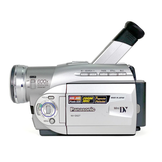
Digital Video Camera/Recorder N-MECHANISM SPECIFICATIONS 2001 Matsushita Electric Industrial Co., Ltd. All rights reserved. Unauthorized copying and distribution is a violation of law. World of free manuals...
www.freeservicemanuals.info 23/7/2013 3. DISASSEMBLY PROCEDURE Item Fig. Procedure Dumper Fig. 1 Release Eject Lever Fig. 2 Release Lock(A) Garage U. Fig. 3-1 Disengage Joints(B) at S and T sides Fig. 3-2 Disengage Joints(C) at S and T sides (*S side first) Mechanism Flexible Cable Fig.
Page 74
www.freeservicemanuals.info 23/7/2013 Item Fig. Procedure 15 Connection Worm Fig. 15 Take Connection Worm Gear out 16 Mode SW Gear Fig. 16 Take Mode SW, T Load and Center Gears out 17 T Load Gear 18 Center Gear Fig. 1 Fig. 2 Fig.
Page 75
www.freeservicemanuals.info 23/7/2013 Fig. 3-2 Fig. 4 Fig. 5-1 World of free manuals...
Page 76
www.freeservicemanuals.info 23/7/2013 Fig. 5-2 Fig. 6 Fig. 7-1 World of free manuals...
Page 77
www.freeservicemanuals.info 23/7/2013 Fig. 7-2 Fig. 7-3 World of free manuals...
Page 78
www.freeservicemanuals.info 23/7/2013 Fig. 7-4 Fig. 7-5 World of free manuals...
Page 79
www.freeservicemanuals.info 23/7/2013 Fig. 7-6 Fig. 8 World of free manuals...
Page 80
www.freeservicemanuals.info 23/7/2013 Fig. 9 Fig. 10 Fig. 11 NOTATION PUBLIC "-//ALDUS//NOTATION TAGGED IMAGE FILE FORMAT//EN" ENTITY SYSTEM "d_11.tif" Fig. 12 World of free manuals...
Page 81
www.freeservicemanuals.info 23/7/2013 Fig. 13 Fig. 14 World of free manuals...
Page 82
www.freeservicemanuals.info 23/7/2013 Fig. 15 Fig. 16 World of free manuals...
www.freeservicemanuals.info 23/7/2013 4. ASSEMBLY PROCEDURE Item Fig. Oil & Procedure Grease Center Gear Fig. 1 Install Center Gear Mode SW Gear Grease Install Mode SW Gear T Load Gear Fig. 2 Grease Install T-Load Gear so that triangle phase marks on Mode SW and T Load Gears meet each other.
Page 84
www.freeservicemanuals.info 23/7/2013 Item Fig. Oil & Procedure Grease 14 TR Band & TR Arm U. Fig. 11- Connect TR Arm and TR Band Fig. 11- 1) Make full unloading condition with 3V bat / 2) Install TR Arm U. Fig. 11- Adjust Tension Fig.
Page 85
www.freeservicemanuals.info 23/7/2013 Fig. 1 Fig. 2 World of free manuals...
Page 86
www.freeservicemanuals.info 23/7/2013 Fig. 3 Fig. 4 World of free manuals...
Page 87
www.freeservicemanuals.info 23/7/2013 Fig. 5 World of free manuals...
Page 88
www.freeservicemanuals.info 23/7/2013 Fig. 6 Fig. 7 Fig. 8 World of free manuals...
Page 89
www.freeservicemanuals.info 23/7/2013 Fig. 9 Fig. 10-1 Fig. 10-2 World of free manuals...
Page 90
www.freeservicemanuals.info 23/7/2013 Fig. 10-3 World of free manuals...
Page 91
www.freeservicemanuals.info 23/7/2013 Fig. 10-4 Fig. 11-1 World of free manuals...
Page 92
www.freeservicemanuals.info 23/7/2013 Fig. 11-2 Fig. 11-3 World of free manuals...
Page 93
www.freeservicemanuals.info 23/7/2013 Fig. 11-4 Fig. 11-5 World of free manuals...
Page 94
www.freeservicemanuals.info 23/7/2013 Fig. 12-1 Fig. 12-2 World of free manuals...
Page 95
www.freeservicemanuals.info 23/7/2013 Fig. 12-3 Fig. 13 World of free manuals...
Page 96
www.freeservicemanuals.info 23/7/2013 Fig. 14-1 Fig. 14-2 World of free manuals...
Page 97
www.freeservicemanuals.info 23/7/2013 Fig. 15 World of free manuals...
www.freeservicemanuals.info 23/7/2013 5. MECHANICAL ADJUSTMENT 5.1. ADJUSTMENT TABLE 5.2. ADJUSTMENT PROCEDURE World of free manuals...
Page 99
www.freeservicemanuals.info 23/7/2013 Item Procedure Confirmation of Tape Running Equipment 1. Mini DV Cassette Specification Refer to Fig. 1-1 and Fig. 1-2 1) Confirm each post position in playback mode. (Fig. 1-1) 2) Confirm condition of tape regulation of each post in playba and review modes.
Page 100
www.freeservicemanuals.info 23/7/2013 Fig. 2-1 Fig. 2-2 World of free manuals...
Page 101
www.freeservicemanuals.info 23/7/2013 Fig. 2-3 Fig. 2-4 Fig. 2-5 6. EXPLODED VIEWS World of free manuals...
www.freeservicemanuals.info 23/7/2013 6.1. VCR MECHANISM SECTION 7. REPLACEMENT PARTS LIST 7.1. VCR MECHANISM SECTION PARTS LIST World of free manuals...
Page 103
www.freeservicemanuals.info 23/7/2013 Ref. No. Part No. Part Name & Description Remarks VEG1576 CYLINDER U. VMC1702 CYLINDER SPRING VXA6999 REEL PLATE U. VMC1701 TR BAND VDG1498 CENTER GEAR VXA6997 IDLER U. VXA7001 MODE SW U. VXA7002 T LOAD GEAR U. VDG1496 CONNECTION WORM VDG1497 BRAKE GEAR...