
Related Manuals for ANK The Artiste EL34


Summary of Contents for ANK The Artiste EL34
- Page 1 EL34 Triple C-Core Monoblock "The Artiste" Construction Manual Version 3.03, July 2019 audionotekits@rogers.com 1-613-822-7188...
-
Page 2: Table Of Contents
Table of Contents Section 1 — Introduction ……………………………………………..………………………….…………….……… About ANK Audio Kits ……………………………………………..………………………….…………….……… Basic Operation of the Amplifier ………………………………….…………………..…….……… 1.2.1 Overview ………………………………….……………………………………………..…….……… 1.2.2 Schematic ……………………………………………….……..……………………………….……… 1.2.3 Component Placement ………………………………….……..……………………………….……… 1.2.4 Block Diagram ………………………………………………………………………….……..…….……… Equipment ……………………………..…………………………………………………………………….………. 1.3.1 Overview of the Kit ……………………………………………………….………….…….….……... - Page 3 Section 3 — Choke Installation ……………………………………………………………..…..……....…. 32 Overview …………….…………………………………………………………………………..….………..…….…… 32 Installing the Choke …………….……………………..….………………………………………………..…….…… 33 Section 4 — Power Supply Installation ………………………………………………..…..……....…. 34 Overview …………….…………………………………………………………………………..….………..…….…… 34 Parts List …………….…………………………………..….………………………………………………..…….…… 34 Building the Power Supply PCB …………….…………………………………..……………….………..…….…… 35 Initial Power Supply Interwiring …………….…………………………………..…..………..…….……...
- Page 4 Section 10 — Final Thoughts ……………………..………………………….…………………….…...………… 10.1 Congratulations ……………………..………………………………………..…………………………………… 10.2 Cables …………………………………..………………………….……………………………………………….…...………… 10.3 Tube Rolling ……………………..………………………….……………………………………………….…...………… 10.3.1 ECF80 ……………………..…………………..……….………………………..……………………...…………… 10.3.2 EL34 ……………………..…………………..……….………………………..……………………...…………… 10.3.3 5U4G …………………………………..………………………………………………………….…….…………… 10.4 Thanks ……………………..…………………………………………………..……………….…………….………………….… Appendix ……………………………………………..……………………………………………………..….……….……….…… 61 Resistor Color Code Reference …………………………………………………………….………….…..…….…… 62...
-
Page 5: Section 1 - Introduction
Section 1 Introduction Thanks for purchasing the ANK Audio Kits EL34 Triple C-Core Monoblock – "The Artiste". We believe it is truly the finest EL34 amplifier on the planet! Our goal is to provide you with the highest quality kit that you will build from scratch with these instructions. -
Page 6: About Ank Audio Kits
As a result, ANK Audio Kits began offering this service for Level 4 and 5 products so that a significant investment in a kit could be turned into a work of art! Since ANK Audio Kits was born in 2004, over 2,500 kits have been shipped to customers worldwide. -
Page 7: Basic Operation Of The Amplifier
1.2.1 Overview ANK Audio Kits is pleased to announce the EL34 Triple C-Core Monoblock – "The Artiste". There is something very special about the music that flows from an EL34 amplifier: gorgeous midrange, transparent highs, and solid bass. "The Artiste" is an ideal power amplifier and an exceptional value. -
Page 8: Schematic
1.2.2 Schematic Schematics change as product development continues, so, while it may be helpful, don't overly rely on this schematic. The build instructions are the most current reference. -
Page 9: Component Placement
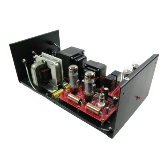
1.2.3 Component Placement Let's take a look at the overall layout of the amplifier:... -
Page 10: Block Diagram
1.2.4 Block Diagram Here's another way of looking at how the manual sections fit into the 'big picture': the sections basically follow how the components are positioned in the amplifier chassis:... -
Page 11: Equipment
Equipment Here is the list of equipment that will be required: Philips screwdriver A pair of quality wire strippers A large, organized work area Soldering iron station with wet sponge Lead-based solder (4% Silver is recommended) 1.3.1 Overview of the Kit In your kit you will find a series of kit bags containing all the hardware, wire, and parts for the... -
Page 12: Components
That way of looking at things sometimes now no longer applies. Please be assured that all resistors supplied with ANK Audio Kits are rated at least per the specified wattage: in some cases, a higher than specified wattage may be supplied. -
Page 13: Diodes
1.4.6 Diodes match the stripe on the diode with When installing diodes note that they are oriented with a stripe — the banding (||) stencil on the board. 1.4.7 Hardware/Mechanical Not all of us are mechanically oriented. So, the kit is well laid out such that all the hardware is provided and bagged in individual sections, so things should make sense. -
Page 14: Wire Color
1.4.10 Optional Finishing Touches From time to time we get asked about some of the build details of the ANK Finished Products that you can see in the pictures in the "Assembled Kits Gallery!" (https://ankits.smugmug.com/) on our website. -
Page 15: Organization Of This Manual
There are sufficient voltages in this kit to give you a very nasty and harmful shock, so be careful when powering on, debugging, and probing around. Please contact ANK Audio Kits via phone or email (audionotekits@rogers.com) to discuss any precautions necessary when building the kit if you feel unsure about what you are doing at any... -
Page 16: Section 2 - Mechanical Assembly And Initial Mains Transformer Wiring
Section 2 Mechanical Assembly and Initial Mains Transformer Wiring In this section we will install the feet, IEC socket, Rocker Switch, and the IEC PCB. Before we begin, It's a good idea when you receive the kit to do a complete inventory. You should see the following parts: ... - Page 17 Here's a graphic for reference showing the various Mains transformer windings that will be used for the HT and various filament needs throughout the amplifier:...
-
Page 18: Installing The Feet
Installing the Feet Take the 4 feet and the M4 x 20mm screws and M4 nuts and washer and mount the feet into the four corners of the chassis, as shown below. -
Page 19: Installing The Rocker Switch And Iec
Feet installed on the chassis Installing the Rocker Switch and IEC Be sure to install it with the narrow Install the Rocker Switch, which just snaps into position. switch lugs nearest the side of the chassis. Use M3 screws to Install the IEC plug; it can mount from inside the chassis or from the outside. sure to install it with the IEC Ground at the bottom of the chassis.. -
Page 20: Installing The Speaker Posts
Installing the Speaker Posts Install the speaker posts found in chassis fittings bag. Let's do it, from top to bottom: Black Note the insulation against the chassis The view from inside the chassis:... -
Page 21: Installing The Rca Jack
Installing the RCA Jack Next, we'll install the RCA jack for the input to the amplifier. It goes in the hole to the edge side of the chassis near the speaker posts. Insert into the chassis from the outside: The white insulating washer with the raised ring facing inwards into the hole ... -
Page 22: Installing The Mains Transformer
Installing the Mains Transformer Now we're going to install the T-191 Mains transformer. We suggest that you read through this entire section to see what you will be doing before starting in on it. Install the rubber strips on the chassis in the position where the T-191 Mains transformer will go. -
Page 23: Installing The Chassis Ground Screw
Position the T-191 Mains transformer (double check the code on the bottom!) into the chassis such that the two White, two Black, and one Green wires go towards the back of the chassis, as shown below. These wires are the Primary. Secure the Mains transformer to the chassis using the provided hardware in the "Mains"... -
Page 24: Installing The Chassis Ground
Installing the Chassis Ground Now let's prepare the Green Ground wire. Insert the Green wire into the provided Ground lug and solder it in place. Do this by adding solder through the front of the lug, as shown below. Add a fair bit of solder and apply heat for at least ten seconds, as the solder must “take” to connect to the lug. -
Page 25: Iec Pcb Wiring
IEC PCB Wiring Now we'll wire the IEC PCB, which will make the remaining wiring from the Rocker Switch to the Mains transformer much easier to follow and to implement. 120V and 240V Operation Cut the four wires (White, White-Grey, Black, and Black-Grey) coming out of the Mains Primary to 30 cm. - Page 26 120V Operation ONLY Add the two jumpers as shown. (You can use the left over end of the Black Primary wire.) 240V Operation ONLY Add one jumper as shown. (You can use the left over end of the Black Primary wire.)
- Page 27 120V and 240V Operation Referencing the appropriate diagram below (they're identical except for the jumpers you've already installed), complete the IEC/rocker switch wiring as follows: Tin and solder the unprepared ends of the half-prepared Red and Black wires in the IEC bag onto the IEC PCB, as shown.
-
Page 28: Connecting And Mounting The Iec Pcb
2.10 Connecting and Mounting the IEC PCB Again, referencing the diagrams below,... - Page 29 Push the crimped ends of the Red and Black wires coming from the IEC PCB onto the left lugs of the rocker switch, Red on top, Black below. Apply the pressure necessary to position the wires correctly onto the lugs. Using the prepared Blue–Brown twisted and crimped pair of wires, connect the IEC socket —...
- Page 30 Finally, let's make the chassis Ground connections. Retrieve the Green ground wire from the Mains transformer and the Green IEC ground wire, using a nut, tightly secure the two grounds: the Green Mains Primary wire and the Green wire from the bottom lug of the IEC socket to the chassis ground lug, as shown below. Next, let's test these important connections.
- Page 31 Time for a break!
-
Page 32: Section 3 - Choke Installation
Section 3 Choke installation Overview In this section we'll install the Choke, which is called the CH-40W A choke is an inductor that is used to smooth the power supply voltage. -
Page 33: Installing The Choke
Installing the Choke With the Mains installed we now want to install the CHOKE which is called the CH-40W. Position in the chassis as shown below and secure it with 4 x M4 10mm screws. We'll connect the Choke later in the Power Supply section. -
Page 34: Section 4 - Power Supply Installation
Section 4 Power Supply Installation Overview In this section we'll be building the Power Supply board. Parts List The Power Supply PCB will be populated with the parts from the Power Supply bag. Quantity Type Designator Power Supply PCB 8-pin valve bases 30uf Mundorf polypropylene capacitors C1, C2 2A fuse... -
Page 35: Building The Power Supply Pcb
Building the Power Supply PCB Let's start by installing the 4 standoffs provided and securing them with 4 M4 screws. From the top of the PCB, insert a screw through each of the four holes in the corners of the PCB and attach the standoffs. - Page 36 each pin to the board: perhaps just start with two pins which are opposite to each other to make sure the base stays level — then you can add more solder to the pins. In the end you can fill up the entire valve base hole.
-
Page 37: Initial Power Supply Interwiring
Initial Power Supply PCB Interwiring We'll now complete the initial Power Supply PCB Interwiring, particularly the wires coming from the Mains Secondary and the Choke. You should measure the lengths of all the wires shown in the diagram below to make sure that they are not too long or too short. - Page 38 Take the Blue and Yellow wires from the Mains Secondary, twist them together, and route them along the edge of the chassis (as shown below) and wire them to the locations on the board as shown in the graphic. Orientation does not matter: either wire can go to either location, as its AC. Connect the Green/Yellow wire from the Mains Secondary to one of the 0/CT tabs as shown.
-
Page 39: Section 5 - Driver Board Installation
Section 5 Driver Board Installation Overview... -
Page 40: Installing The Valve Bases
Installing the Valve Bases The first step is to install the 6 standoffs for the board itself. Don't attach the PCB to the chassis yet; we have a lot of work to do before that! Using the tips in the Power Supply section regarding making sure that the valve bases are level, solder the 9-pin valve base to the board at V1. - Page 41 A quick lesson about resistors: A resistor that reads 100R means that it is 100 ohms; the 'R' stands for resistance A resistor that reads 2K7 means it is 2700 ohms ; the 'R' is assumed and the K (which stands for Kilo or 1000) is positioned like the decimal place, so it's like reading 2.7K ohms (K = multiplied by 1000) —...
-
Page 42: Installing The Chassis Mounted Resistors
Also, be sure to solder on the underside of the board and check that you have nice little “volcanoes” on each solder joint. And, when you go to clip a lead be sure to clip above the volcano so that you don’t slice off this nice joint. -
Page 43: Installing The Capacitors
Installing the Capacitors Next we'll install the capacitors. Electrolytic Capacitors Quantity Designation Type C1, C20 10uf 160V 100uf 450V, tall, thin style 33uf 350V C15, C16 220uf 100V 22uf 450V We'll start with the electrolytic capacitors. These are the type of capacitors like, for example, the 10uf 160V capacitors at C1 and C20, which have a stripe down one side. - Page 44 Completed Driver board...
-
Page 45: Section 6 - Output Transformer Installation
Section 6 Output Transformer Installation Overview Using the hardware in the C-Core Transformer bag, position and install the output transformer, oriented, as you please, in one of the two ways shown in the pictures below. The chassis is drilled for the orientation in the picture on the left. but if you want to turn it the other way and drill the necessary holes, that's fine too. -
Page 46: Section 7 - Interwiring
Section 7 Interwiring You've certainly accomplished a great deal to get to this point! Now, we'll tackle the interwiring: here's where we make the connections from the Mains transformer Secondary and the Power Supply PCB to the Driver PCB — and from the Driver PCB to the chassis mounted resistors, the output transformer, the RCA jack, and the speaker posts. -
Page 47: Wiring The Filament Wires From The Mains Transformer
Wiring the Filament Wires from the Mains Transformer Have a look at the following graphic: Connect the Grey and Red wires from the Mains transformer Secondary to the 6V3 6A solder tabs on the Driver board. Connect the Blue–White wire to the CT solder tab. These are the EL34 filament wires;... -
Page 48: Wiring The Ht Wires From The Power Supply Board
Wiring the HT Wires from the Power Supply PCB Let's look at how the HT is wired from the Power Supply board to the Driver board: Connect a Red wire from B+ on the Power Supply board to B+/HT on the Driver board, as shown. Connect a Black wire from GND on the Power Supply board to GND on the Driver board, as shown. -
Page 49: Wiring The Output Transformer Secondary And Speaker Posts
Wiring the Output Transformer Secondary and Speaker Posts The output transformer Secondary has three wires: Green, Blue, and Purple. Have a look at the following graphic: Twist together the Purple output transformer Secondary wire and one end of a Red wire — and connect them to the top Red speaker post, as shown. -
Page 50: Wiring The Chassis Mounted Resistors
Wiring the Chassis Mounted Resistors Now we'll wire up the two large Gold 300R 50W chassis mounted resistors. Connect a Red wire between TP1 on the Driver board and the lower lead on one of the 300R resistors, as shown. Connect a Red wire between TP2 on the Driver board and the upper lead on the other 300R resistor, as shown. -
Page 51: Wiring The Rca Jack
Wiring the RCA Jack The final interwiring connections involve connecting the prepared Yellow AN-A shielded cable from the RCA jack to the IN and GND solder tabs on the Driver board. Here's the plan: At the RCA jack: Tin the AN-A Red (Signal) lead. Twist the AN-A White (Ground) lead and shield together and tin them. -
Page 52: Wiring The Led
Here's a close-up of the RCA connections: On the Driver PCB: Tin the AN-A Red (Signal) and White (Ground) leads. Neatly cut off the shield. It isn't connected at this end. Connect the Red (Signal) wire to IN. Connect the White (Ground) wire to GND. Wiring the LED Connect the two LED wires to the LED solder lugs near C4, on the right side of the board. -
Page 53: Final Step
Final Step Secure the Driver board in the chassis with 6 M4 screws, from the underside. And here we are, all wired up! Another cup perhaps? Before we go to the next section, where we're going to power on the amplifier and do some voltage checks, it’s a really good idea to check over your work, particularly this last section, the interwiring. -
Page 54: Section 8 - Turn-On Procedure And Testing
Section 8 Turn-on Procedure and Testing Turn-on Install a fuse into the fuse drawer in the IEC drawer. You can use the 2A fuse supplied (Slo-Blo). Install the 2 5U4G rectifier tubes on the Power Supply board. Install the ECF80 tube on the Driver board. Take the dummy load that is supplied (this is basically an 8 ohm 10W resistor) and connect it to the 0 and 8 ohm speakers posts as shown below. -
Page 55: Measuring The Ht Voltage
Measuring the HT Voltage Now, with the power on, a good first test is to measure the HT (high voltage DC). On the Power Supply board, measure the HT by using the Red probe on the B+ and the Black probe on GND. -
Page 56: Measuring The Filament Voltages
Measuring the Filament Voltages Next, we'll check the AC filament voltages that go to the EL34 tubes. Put your meter on AC and measure between pins 2 and 7, as shown. You should see around 6.7 volts. This is a "loaded" value;... - Page 57 Power the unit on, put your meter on DC, and measure the two test points, TP1 and TP2, to GND. These are the CATHODES of the EL34s and, if you get a voltage here in the 22V DC range (the 25.48V DC in the picture below is fine!), you can be confident that the amplifier is 99% working.
-
Page 58: Section 9 - Finishing Touches
Section 9 Finishing Touches Installing the Front Faceplate Remove the protective films from the front and back of the front faceplate. Install the front faceplate using four Black M4 CSK flat head screws. Installing the LED Carefully trim the LED leads so that they are not exposed. Glue or attach (with some Blu Tack) the LED holder to the front panel so that the LED protrudes through the designated hole, as shown below: Installing the Chassis Top... -
Page 59: Section 10 - Final Thoughts
Section 10 Final Thoughts 10.1 Congratulations If you've made it to this point then CONGRATULATIONS! — you are ready to insert your amplifier into your system and enjoy it. 10.2 Cables In our experience, a high quality power cable and good interconnects should make a noticeable improvement to the sound. -
Page 60: Tube Rolling
10.3 Tube Rolling 10.3.1 ECF80 We feel that the sound of the ANK Audio Kits EL34 Triple C-Core Monoblock – "The Artiste" is truly sublime. It provides a highly detailed and transparent presentation with gorgeous sonics. Rolling some quality new production tubes and/or some nice NOS tubes in the ECF80, EL34, and 5U4G positions will allow you to tailor the sound to your particular preferences. -
Page 61: Appendix
Appendix... -
Page 62: Resistor Color Code Reference
You can also find an 'Interactive Resistor Color Code Calculator' on our website (available from the Links page).
Need help?
Do you have a question about the The Artiste EL34 and is the answer not in the manual?
Questions and answers