Table of Contents
Advertisement
Advertisement
Table of Contents

Related Manuals for Fona XDG


Summary of Contents for Fona XDG
- Page 1 FONA XDG Service and Installation Manual English...
-
Page 2: Table Of Contents
FONA XDG – Service & Installation Manual FONA XDG Service and Installation Manual English Edition Version 150715 July 2015 Code 69 550 70210 Manufactured by FONA S.r.l. Via Galilei 11 - 20090 Assago (MI) Italy Distributed by FONA Dental s.r.o. - Page 3 FONA XDG – Service & Installation Manual The Control Panel Device for emission of ionizing Maxillary incisor radiation on request Indication of system turned on and Maxillary canine or premolar ready Maxillary molar Irradiation Alarm Mandibular incisor mAs display, the controlled...
-
Page 4: Introduction
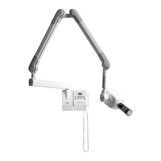
1. INTRODUCTION Purpose The FONA XDG X-ray Equipment is designed to fulfil the needs for high resolution intra-oral radiography in the general dental practice. The systems can be configured for wall, mobile solutions. The Operator’s Manual and the Service and Installation Manuals supplied with the system are integral part of the product. -
Page 5: Technical Data
FONA XDG – Service & Installation Manual 2. TECHNICAL DATA System Supply Line Voltage 110-120 V (from 99 V to 132 V in sub-ranges depending on THA mounted) 220-240 V (from 198 V to 264 V in sub-ranges depending on THA mounted) -
Page 6: Assembly And Installation
FONA XDG – Service & Installation Manual 3. ASSEMBLY AND INSTALLATION Wall Mounted Systems 3.1.1 Installation Options The timer box can be mounted together with the X-ray head on the right of the wall adaptor or can be placed remote either inside or outside the examination room. The release hand-switch can be directly connected to the timer box or placed remote making use of specific mounting kit including 10 m cable. - Page 7 FONA XDG – Service & Installation Manual 3.1.4 Electrical Requirements The power line cable must be connected to the input terminals (IN) of the timer to supply the timer itself and to make available power for the X-ray head at the output terminals (OUT), upon request by the operator (via the hand switch).
- Page 8 FONA XDG – Service & Installation Manual 3.1.5 Mounting and Connecting Sequence Step 1 Mount the Wall Adaptor Step 7 Connect the Hand-Switch Step 2 Mount the Timer Step 8 Optional Remote Hand-Switch Step 3 Mount the Support Arm Step 9...
- Page 9 FONA XDG – Service & Installation Manual 3.1.7 Mounting the Timer Use the mounting plate or the template to mark the holes on the wall. Remove the plastic cover after having taken away the blocking screws behind the logo strip. Pay attention when disconnecting the flat cable of the control panel from the control board.
- Page 10 FONA XDG – Service & Installation Manual 3.1.9 Mounting the Scissor Arm WARNING. THE SPRINGS IN THE SCISSOR ARM MAY CAUSE INJURY TO THE INSTALLER AS WELL AS DAMAGE TO THE ARM ITSELF IF NOT HANDLED PROPERLY. DO NOT REMOVE...
- Page 11 FONA XDG – Service & Installation Manual 3.1.10 Connecting the Wall Adaptor with Timer at side MAINS LINE INPUT TO TIMER YELLOW-GREEN SUPPLY CABLE BONDING OUTPUT TO CONDUCTOR OF TUBE HEAD SUPPORT ARM SUPPLY CABLE FROM TIMER TO TUBE HEAD...
- Page 12 FONA XDG – Service & Installation Manual Remove from the common bolt for bonding and grounding on the wall adaptor the existing cable for ground provision. BOLT FOR BONDING AND GROUNDING SUPPLY CABLE FROM REMOTE TIMER TO TUBE SUPPLY HEAD...
- Page 13 FONA XDG – Service & Installation Manual 3.1.12 Connecting the Timer FUSE F4 NEUTRAL GROUND ZERO OHM LIVE RESITOR HAND-SWITCH CONNECTION JUMPERS FUSE F2 HAND-SWITCH SOCKET TST2 HAND-SWITCH SOCKET TST1 FUSE F1 Turn-off the voltage supply line. Connect the three wires from the voltage supply to the terminal block (IN on the left) but do not connect any outgoing wire (OUT on the right) to Wall Adaptor.
- Page 14 FONA XDG – Service & Installation Manual Jumpers are available to activate properly the hand-switch connection: Position TST1 to enable external socketTST1, Position TST2 to enable the internal socket TST2, Position TST1/2 f to enable the internal and the external sockets.
- Page 15 The nominal line voltage of the X-ray head (see label). Set dip switch 4 to the anode current set in the X-ray head label, which is 3.5 mA for FONA XDG. Set the pre-heating time according to type of X-ray insert used in the X-ray head assembly;...
-
Page 16: Dip Switch Setting
FONA XDG – Service & Installation Manual Dip Switch Setting DIP 4 DIP 8 ANODE CURRENT TECHNIQUE FACTOR DISPLAYED DIP 1 TECHNIQUE DIPS 2-3 DIPS 5-6-7 FACTOR TUBE HEAD PRE HEATING CORRECTION TYPE TIME DIP 1 DIPS 5 – 6 – 7... -
Page 17: Layout Power Board Timer
FONA XDG – Service & Installation Manual Layout Power Board Timer POWER SUPPLY 5 V LED SET-UP KEYBOARD MICROSWITCHES CONNECTOR BACK UP TIMER TEST POINT & LED MICROPROCESSOR WATCH DOG LED POWER SUPPLY 24 V LED 5VA TRANSFORMER PRIMARY 115/230 V... -
Page 18: Mobile Systems
FONA XDG – Service & Installation Manual Mobile Systems 3.4.1 Unpacking Unpack the components of the system and check the following: Each item is in good conditions and was not damaged during transportation. All the items for the desired system configuration are available. -
Page 19: Mounting The Timer
FONA XDG – Service & Installation Manual Mounting the Timer The timer is blocked in place with four bolts. 3.5.1 Connecting the Line voltage cable The line voltage cable for the mobile has to be completed with local plug. The power supply cord bonding... -
Page 20: Maintenance
User to properly maintain the equipment may relieve the Manufacturer, or its Agent, from responsibility for any injury, damage or non compliance which may result. Maintenance for the FONA XDG system to be done regularly by a service technician at least once every 24 months, with regular checks performed by the operator every year. -
Page 21: Maintenance Of Scissor Arm
FONA XDG – Service & Installation Manual Maintenance of Scissor Arm FRICTION SPRING POINT 3 TUNING POINT FRICTION POINT 2 SPRING FRICTION TUNING POINT 4 POINT Balance the arms (2 sections) and tune frictions (4 points) if needed in normal conditions with X-ray head mounted. -
Page 22: Maintenance Of X-Ray Head
FONA XDG – Service & Installation Manual Maintenance of X-ray Head HOLDING POSITION OF 8 SCREW DISK SPRINGS IN BLOCKED FRICTION SCREW 4 GROUPS OF 2 Inspect for damage/wear to the X-ray tube- head and support system. FRICTION Inspect for oil leakage. Replace tube-head if necessary. -
Page 23: Service Functions
FONA XDG – Service & Installation Manual Service Functions READING EXPOSURE COUNTER. Enter by switching ON the unit while pressing at the same time for 2 s, the three keys plus , minu s , and upper incisor The cumulative... -
Page 24: Measurements
FONA XDG – Service & Installation Manual 5. MEASUREMENTS All measurements to be done with the equipment supplied at nominal line voltage with specified line resistance. The tolerances on the measured values have to take into account the precision of each measurement instrument. -
Page 25: Leakage Radiation
The applicable technique factors for FONA XDG are of 70 kV and 3.5 mA. The point of maximum leakage has to be considered, excluding the direction of the primary beam. The duty cycle factor has also to be taken into account for the computation of the actual dose rate. -
Page 26: Appendix A Systems And Components
FONA XDG – Service & Installation Manual Appendix A Systems and Components FONA XDG Systems FONA XDG Systems FONA XDG Systems at 230 V at 240 V at 120 V Description Code Code Code Wall Syst. Arm S 30 cm... -
Page 27: Appendix B Icons
FONA XDG – Service & Installation Manual Appendix B Icons IEC Type B Compliance to European Equipment Community Requirements X-ray On Compliance to Canadian and US Irradiation Standards Line voltage supply On - System Examine Annexed Documentation Ready Off (Disconnected from Line voltage... -
Page 28: Appendix C Exposure Table
FONA XDG – Service & Installation Manual Appendix C Exposure Table Upper Upper Canine/ Upper Incisor Premolar Molar Lower Lower Large Small Lower Canine/ Molar or Patient Patient Incisor Premolar Bitewing 0.21 0.28 0.35 0.42 0.32 0.28 0.35 0.42 0.56... -
Page 29: Appendix D Alarm Conditions
FONA XDG – Service & Installation Manual Appendix D Alarm Conditions Timer Alarm Conditions Code Fault /Error Signal Reset By acknowledgement X-ray requested during Green lamp on the panel or when A 01 cool-down period (System Ready) flashing system has cooled... -
Page 30: Appendix E Identification Labels
FONA XDG – Service & Installation Manual Appendix E Identification Labels 30/32 69 550 70210 150715... -
Page 31: Appendix F Cooling Curves
FONA XDG – Service & Installation Manual Appendix F Cooling Curves COOLING CURVE OF X-RAY INSERT Time (min) COOLING CURVE OF TUBE HOUSING ASSEMBLY Time (min) 150715 69 550 70210 31/32... - Page 32 We reserve the right to make any alterations which may be required due to clinical improvements FONA XDG Service and Installation Manual – English Edition 150715 FONA Dental s.r.o. FONA S.r.l. *6955070210* Via Galilei 11 - 20090 Assago Stefanikova 7 SK-811 06...
Need help?
Do you have a question about the XDG and is the answer not in the manual?
Questions and answers
I have malfunctioning blue x70. Can I get the motherboard or timer panel separately?