Advertisement
Operating manual
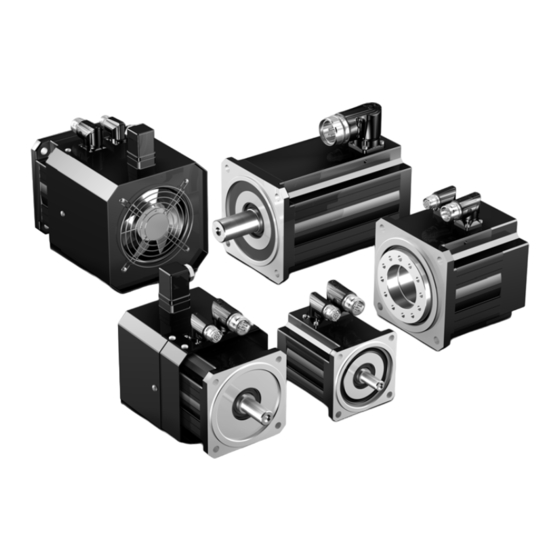
EZ/EZHD/EZHP synchronous servo motors, EZS/EZM synchronous servo motors for screw
drive
These operating instructions contain information about the
transport, installation and commissioning of STOBER EZ,
EZHD, EZHP synchronous servo motors and EZS, EZM syn-
chronous servo motors for screw drive.
For further details, see the catalog with the ID 442437.
In the event of any unclear points, we recommend that you
contact STÖBER with the model designation and serial num-
ber, or have the installation and maintenance work carried out
by a STÖBER service partner.
1
Operation in accordance with its in-
tended use
Synchronous servo motors must be used exclusively for op-
erating machines and systems together with servo inverters.
Stay within the limits defined by the technical data.
Do not use synchronous servo motors in potentially explosive
atmospheres.
For reasons of operational safety, motors may only be used
for the single application for which they were projected.
Any overload on the drives is considered unintended use.
The information and instructions in these operating instruc-
tions must be precisely followed to ensure that claims submit-
ted under the warranty will be honored. If modifications are
made to motors, warranty claims will be rendered void.
Comply with the safety instructions in these operating instruc-
tions and in all supplementary documents for the synchro-
nous servo motor and other components such as gear units
and servo inverters.
05/2019
2
Technical data
The technical data for synchronous servo motors, geared mo-
tors and servo inverters that are used is indicated on the rel-
evant nameplates.
Designs:
IMB5, IMV1, IMV3
(DIN EN 60034-7)
Protection class:
EZ, EZHD: IP56
EZHP: IP56 / IP66 (option)
EZS, EZM: IP40
(DIN EN 60529)
Protection class:
I
Thermal class:
155 (F) (DIN EN 60034 / VDE 0530)
155 °C, heating ΔT = 100 K
Surrounding
-15 °C to +40 °C (with water cooling +5
temperature:
°C to +40 °C)
Installation altitude: up to 1000 meters above sea level
Cooling:
For IC 410 convection cooling;
or optional IC 416 convection cooling
with forced ventilation (DIN EN 60034-
6), see 2.4.1;
or optionally for water cooling in the A-
side motor flange, see 2.4.2
Surface:
Black matte as per RAL 9005
Please note! Repainting will change
the thermal properties and therefore
the performance limits of synchronous
servo motors.
Vibration intensity: as per DIN EN 60034-14 degree N
(half wedge balancing for shafts with
key).
Winding:
Three-phase, single-tooth design
Connection
see motor connection diagrams
method:
Acceleration / shock load in operation:
The following value for the shock load indicates the value up
to which the motor can be operated without loss of functional-
ity: 50 m/s² (5 g), 6 ms (maximum value as per DIN EN 60068-
2-27).
Brace the motor connection cable close to the motor so that
vibrations of the cable are not transferred to the motor.
When connecting the motors to drive units such as gear units
or pumps, take into consideration the permissible shock loads
and tilting torques of the units.
Information
If brakes are installed, the holding torques may
be reduced by the shock load!
1
www.stober.com
ID 443032_en.01
Advertisement
Table of Contents

Subscribe to Our Youtube Channel
Related Manuals for Stober EZ Series


Summary of Contents for Stober EZ Series
- Page 1 Technical data These operating instructions contain information about the transport, installation and commissioning of STOBER EZ, The technical data for synchronous servo motors, geared mo- EZHD, EZHP synchronous servo motors and EZS, EZM syn- tors and servo inverters that are used is indicated on the rel- chronous servo motors for screw drive.
-
Page 2: Temperature Sensor
2.1 Temperature sensor 2.1.3 Temperature sensor KTY Optionally the temperature-dependent resistor KTY 84-130 STOBER synchronous servo motors are equipped with a can be installed as a temperature sensor in one phase of the PTC thermistor to realize thermal winding protection as stan- motor winding. -
Page 3: Motor Cooling
Technical data can be found in the gravity-loaded vertical axes. Therefore the machine man- nameplate of the motor and in the relevant STOBER catalog. ufacturer must take additional measures to minimize risks (for example by providing a mechanical substruc- CAUTION! ture for maintenance work). -
Page 4: Safety Information
EZ4 – EZ5: 6 l/min ( 4.5 l/min) In this case, stop the drive as quickly as possible and contact EZ7 – EZ8: 7.5 l/min ( 5.0 l/min) STOBER Service. 2.5 Warning labels on the motor 3.3 Safety during installation and mainte- Warning labels are attached to the motor. - Page 5 Operating manual EZ/EZHD/EZHP synchronous servo motors, EZS/EZM synchronous servo motors for screw drive www.stober.com 3.5 Synchronous servo motors EZHD, Transportation and storage EZHP 4.1 Transportation NOTICE Use the ring screws in the motor housing for vertical transport of the motors. Sling the motors without ring screw with a suit- The hollow shaft of the motors moves in relation to the able support cable directly on the gear unit housing.
-
Page 6: Maintenance
Operating manual EZ/EZHD/EZHP synchronous servo motors, EZS/EZM synchronous servo motors for screw drive www.stober.com 5.1 Assembly of the motors/geared mo- WARNING! tors EZHD/EZHP Risk of injury due to moving parts! The motors/geared motors can be operated in any installation Before switching on the drive, check the following: position. - Page 7 Operating manual EZ/EZHD/EZHP synchronous servo motors, EZS/EZM synchronous servo motors for screw drive www.stober.com 10 Disposal This product contains recyclable materials. Observe local ap- plicable regulations for disposal. ID 443032_en.01 05/2019...
Need help?
Do you have a question about the EZ Series and is the answer not in the manual?
Questions and answers