Table of Contents
Advertisement
Quick Links
Advertisement
Table of Contents

Related Manuals for SEWHA CNM SI 4400

Summary of Contents for SEWHA CNM SI 4400
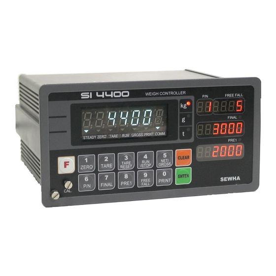
- Page 1 Digital Weighing Controller SI 4400 Instruction Manual Ver. 3.18 May. 2011...
-
Page 2: Table Of Contents
DIGITAL WEIGHING CONTROLLER SI 4400 CONTENTS 1. Before Installation 3 page --------------- 2. Introduction 4 page --------------- 3. Specification 5 page --------------- 4. Installation 11 page --------------- 4-1. External Dimension & Cutting Size 11 page --------------- 4-2. Load Cell Installation... -
Page 3: Before Installation
DIGITAL WEIGHING CONTROLLER SI 4400 1. BEFORE INSTALLATION 1-1. Caution / Warning Marks Warning This mark warns the possibility to arrive death or serious injury in case of wrongly used. Caution This mark cautions the possibility to arrive serious human body injury or product lose in case of wrongly used. -
Page 4: Introduction
With 2ports serial port interfaces and precise weighing control system, you can upgrade your weighing process. This “SI 4400” Weighing Controller is suitable for any kinds of packaging and Filling application various weighing options, like “Auto TARE Tracking mode”. Enjoy your process with “SI 4400” Weighing Controller. -
Page 5: Specification
DIGITAL WEIGHING CONTROLLER SI 4400 3. SPECIFICATION 3-1. Analog Input & A/D Conversion Input Sensitivity 0.2㎶ / Digit DC 10V ( - 5V ~ + 5V ) Load Cell Excitation Max. Input Signal Max.3.2mV/V Temperature Coefficient [Zero] ±16PPM/℃ , [Span] ±3.5PPM/℃... - Page 6 DIGITAL WEIGHING CONTROLLER SI 4400 3-4. Option Card Option No.1 Printer Interface : Centronics Parallel Option No.2 Analog Output (0~10V or 0~5V) Option No.3 Analog Output (4~20mA) Option No.4 Serial Interface : RS-232C / 422 / 485 Option No.5 BCD INPUT (P/N change purpose) Option No.6...
- Page 7 DIGITAL WEIGHING CONTROLLER SI 4400 - 7 -...
- Page 8 DIGITAL WEIGHING CONTROLLER SI 4400 3-5-2. Key Operation Make Weight value as Zero. Under F08, you can set the Zero key operation range, as 2%, or 5%, or 10%, or 20% of Max. Capacity. ※ Under “Tare” key input, Zero key will not be activated.
- Page 9 DIGITAL WEIGHING CONTROLLER SI 4400 - Digit setting Whenever pressing “0”key, digit will be change 1, 2, 5, 10, and 50. - Decimal point position Whenever pressing “0”key, decimal point will be change. 1. Modify the set value during setting process.
- Page 10 DIGITAL WEIGHING CONTROLLER SI 4400 Print current P/N’s accumulated weighing count and weight. (Sub-Total Print) Set “Over N.G”(Error relay) range. (If you set larger value than FINAL value, the setting is not saved) Set “Under N.G”(Error relay) range. (If you set larger value than FINAL value, the setting is not saved) Display accumulated weighing count and weight Max.
- Page 11 DIGITAL WEIGHING CONTROLLER SI 4400 3-6. Rear Panel ② ○ ○ ○ ○ ○ ○ ○ ② POWER AC IN ○ - Power switch : Power on/off switch. - Fuse : AC250V / 0.5A , φ5.25 , 20mm. - AC IN : Available Input AC 110V / 220V.
-
Page 12: Installation
DIGITAL WEIGHING CONTROLLER SI 4400 4. INSTALLATION 4-1. External Dimension & Cutting Size (External Dimension) (unit : mm) (Cutting Size) (unit : mm) 162. 4-2. Installation Components Communication Connector Power Cable Load-cell Cable (D-SUB 9P) - 12 -... -
Page 13: Load Cell Installation
DIGITAL WEIGHING CONTROLLER SI 4400 4-3. Load Cell Installation 4-3-1. Load Cell Connector Specification RED(EXC+) WHITE(EXC-) GREEN(SIG+) BLUE(SIG-) YELLOW(SHLD) 4-3-2. Load Cell Installation 1) You can connect Max. 8pcs of same capacity Load cells at once. (350Ω) 2) You have to make horizontal balance on the ground. - Page 14 SI 4400 4-3-3. Formula to plan the precise weighing system This “SI 4400” weighing controller’s Max. input sensitivity is 0.2㎶ / Digit. And for precise weighing system, the following formula must be satisfied. Caution : “Input sensitivity” means Min. output voltage variation of weighing part to change 1digit. So, Caution please do not make large input voltage to make reliable weighing system.
-
Page 15: Set-Up
DIGITAL WEIGHING CONTROLLER SI 4400 5. SET-UP 5-1. Calibration Adjust weight balance between “Real weight” on the load cell(Weight Part) and “Displayed weight of Indicator”. When you replace LOAD CELL or Indicator, you have to do Calibration process once again 5-2. - Page 16 DIGITAL WEIGHING CONTROLLER SI 4400 p 20. 0 00 6. Press key to save and move to next step. 7. Define the optimal Digit/Division value of weighing measurement. Whenever pressing key, the Digit/Division value will be changed like “1 2 5 10 20 50” .
- Page 17 DIGITAL WEIGHING CONTROLLER SI 4400 l 2. 0 00 12. Input “Test weight” capacity. And press key. Ex) Load Cell CAPA : 20kg, division 0.001 Use test weight(at least 2kg) which is 10% of max CAPA(20kg) input test weight 2.000 13.
-
Page 18: Simulation Calibration Mode(Without Test Weight)
DIGITAL WEIGHING CONTROLLER SI 4400 5-3. Simulation Calibration Mode (Calibrate without Test weight) Through this “Simulation Calibration Mode” you can make simple calibration without Test weight. This calibration mode uses “Load cells’ max. capacity” and “Max. Output Rate(mV)”, the weight adjustment degree might be less than “Test weight Calibration”. - Page 19 DIGITAL WEIGHING CONTROLLER SI 4400 6. Define the optimal position or decimal point p 15000 Whenever pressing key, Decimal point will be changed. p 150. 0 0 7. Press key to save Digit /Decimal point and move to next step.
- Page 20 DIGITAL WEIGHING CONTROLLER SI 4400 Cell0Ut 12. At this step input Max. Output rate(mV) of load cell. o1. 4 5800 13. Input Load cell Output Rate(mV/V) (refer the load cell label) Ex)Load cell Related output : 1.458 mV/V ※ Caution : Due to some variation between “State output rate” and “Real Output rate” of load cell, there might be some weight difference after finishing calibration.
-
Page 21: Set-Up
SI 4400 5-4. Set-up Set-up means set the F-function and make SI 4400 weighing controller will perform more accuracy. (Considering external / internal environmental condition) ※remarks : In case that “P-W” is displayed, you have to check the pass word. - Page 22 DIGITAL WEIGHING CONTROLLER SI 4400 5-5. F-Function List ■ General Function Setting (● Factory default set value) Weighing Data Save Method Selection (Apply on Accumulated weighing count/weight) Manual Save Mode (Save when “Print” key input) ● Automatic Save Mode(Save when “Finish Relay output”) Combined Save Mode (Save when “Print”...
- Page 23 DIGITAL WEIGHING CONTROLLER SI 4400 Digital Filter setting If “B” set value is fixed, “A” set value is A : Frequency Filter setting value (0~3) (0 : about 200Hz/sec, 3 : about 500Hz/sec) large, the indicator will response more B : Buffer Filter setting value (1~9) sensitive.
- Page 24 DIGITAL WEIGHING CONTROLLER SI 4400 “STEADY” condition check time setting During the set time period, estimate weighing part’s “STEADY” condition and display. ∫ If you set small value, indicator will take “STEADY” fast, if you set large value, indicator will take “STEADY” slow.
- Page 25 DIGITAL WEIGHING CONTROLLER SI 4400 Equipment No. setting 1~99 Equipment No. setting with No. key. (01 ~99 settable) ■ Relay Output Mode Setting Automatic Free Fall Compensation setting This function is to compensate “Free fall” value during the weighing process.
- Page 26 DIGITAL WEIGHING CONTROLLER SI 4400 ◆ Weighing Mode 1. – Limit Mode (F21-01 setting) Weight ※ This Flow chart was made based on FINISH FINAL “LOW/HIGH” set value is “0” PRE1 Near Zero TARE Input Output 1 PRE 1 Output 2 FINAL “t1”...
- Page 27 DIGITAL WEIGHING CONTROLLER SI 4400 ◆ Weighing Mode 2. – Packer Mode 1. (F21-02 , F52-00, F53-00 setting : Normal Packer mode) Weight FINISH FINAL HIGH FREE PASS PRE 1 FALL Empty TARE input START Output 1 PRE 1 Output 2...
- Page 28 DIGITAL WEIGHING CONTROLLER SI 4400 ◆ Weighing Mode 3. - Packer Mode 2. (F21-02, F52-01, F53-00 setting) – Auto “TARE” input at start, Manual “TARE RESET” when Finish) Weight FINISH FINAL HIGH Free PASS PRE 1 Fall Empty START Auto TARE input...
- Page 29 DIGITAL WEIGHING CONTROLLER SI 4400 ◆ Weighing Mode 4. – Packer Mode 3 (F21-02, F52-01, F53-01 setting) – Auto “TARE” input at start, Auto “TARE RESET”, When Finish relay is “OFF”.) Weight TARE Weight HIGH PASS FINISH FINAL Auto TARE Reset...
- Page 30 DIGITAL WEIGHING CONTROLLER SI 4400 ◆ Weighing Mode 5. – Packer Mode 4. (F21-02, F52-01, F53-02 setting) – Auto “TARE” input at start, Auto “TARE RESET” input at Empty Relay output) Weight FINAL FINISH HIGH PASS PRE 1 Free Fall...
- Page 31 DIGITAL WEIGHING CONTROLLER SI 4400 ◆ Weighing Mode 6. – Packer Mode 5 (F21-03, F53-00 setting) – “Auto TARE Tracking” at Start input, Manual “TARE reset” at TARE RESET input. Weight FINAL FINISH HIGH PASS PRE 1 TARE weight Check...
- Page 32 DIGITAL WEIGHING CONTROLLER SI 4400 ◆ Weighing Mode 7. – Packer Mode 6. (F21-03, F53-01 setting) – “Auto TARE Tracking” at Start input, Auto “TARE reset”, When Finish relay is “OFF”. Weight TARE Weight FINAL FINISH PRE 1 Auto TARE Reset Point...
- Page 33 DIGITAL WEIGHING CONTROLLER SI 4400 ◆ Weighing Mode 8. – Packer Mode 7. (F21-03, F53-02 setting) – “Auto TARE Tracking” at Start input, Auto “TARE reset”, When Weight is less than “Empty Range(After Finish Relay is “OFF). Weight FINAL FINISH...
- Page 34 DIGITAL WEIGHING CONTROLLER SI 4400 ◆ Weighing Mode 9. – Limit Mode (F21-04 setting) – Before Finish Relay output, there is no LOW/HIGH relay output. Weight ※ LOW/HIGH Relay will be “ON” at the same FINISH FINAL time of “FINISH” relay output.
- Page 35 DIGITAL WEIGHING CONTROLLER SI 4400 “FINISH Relay” delay time(t1) setting After current weight is reached to FINAL, you can set some delay time of “FINISH relay ON time. ∫ “00” setting : At Steady point, FINISH relay output “20” setting : After 2.0sec from Steady point, FINISH relay output “99”...
- Page 36 DIGITAL WEIGHING CONTROLLER SI 4400 ● 9,600bps 14,400bps 19,200bps 28,800bps 38,400bps 57,600bps 76,800bps 115,200bps DATA Transference Method selection ● Simplex Mode / Stream Mode Duplex Mode / Command Mode Print port selection (Under F32-01 setting, only) ● Same port as using for Command Mode.
- Page 37 DIGITAL WEIGHING CONTROLLER SI 4400 ■ Print Mode Setting (These settings will be apply to Serial and Parallel print) Weight Unit selection ● Print Format selection (If you install on Standard Serial Port) Continuous Print ● Serial No. and Weight will be printed continuously.
- Page 38 DIGITAL WEIGHING CONTROLLER SI 4400 Parallel Print Port selection ● Parallel Port is not installed. Share Standard Serial Port. Share Optional Serial Port. Function / Clear key Activation display selection ● Activation display not use Activation display use Auto “TARE” setting, When “Start” input ●...
- Page 39 DIGITAL WEIGHING CONTROLLER SI 4400 ■ Other Setting ※ Under “Other setting mode”, you can not move to other function directly. Press key and move to F01 and move to other function No. directly. EMPTY Range setting You can set “EMPTY” Range.
- Page 40 DIGITAL WEIGHING CONTROLLER SI 4400 ■ Communication Mode setting (Serial Port 2. - Optional Serial port) This setting will be activated only when “Optional Serial Port” is installed. Parity Bit selection Mode ● No Parity Odd Parity Even Parity Serial Communication Speed selection...
- Page 41 DIGITAL WEIGHING CONTROLLER SI 4400 6. INTERFACE 6-1. Serial Interface (RS-232C) RS-232C Serial Interface is sensitive/weak for electric Noise. So, please isolate with AC power cable and use shield cable to reduce the electric noise effect. 6-1 Communication with PC(Personal Computer) or Other devices...
- Page 42 DIGITAL WEIGHING CONTROLLER SI 4400 ⑧ Check-Sum (Error Detecting, “F-Function 36”) Parity Stop Data Byte – Refer “F40” Start Bit 6-1-4. Data Format(1) : ID Number will not be transferred. (Refer “F-function 37”) Including Decimal point Header 1. Header 2.
- Page 43 DIGITAL WEIGHING CONTROLLER SI 4400 ST : Display “Steady” US : Display “Un-Steady” ② Header 2. : NT : Net-Weight GS : Net-Weight, under TARE. ③ Data Bit(Number) 2B(H) : “+” Plus 2D(H) : “-“ Minus 2D(H) : “ “ Space 2E(H) : “.”...
- Page 44 DIGITAL WEIGHING CONTROLLER SI 4400 6-1-7. Data Format : AD – 4321 Data Transference) – AD – 4321 18byte Format +,- / Including Decimal point 8byte Weight Header 1 Header 2 Data(8) Unit ① Header 1. : OL : Over Load, Under Load ST : Display “Steady”...
- Page 45 DIGITAL WEIGHING CONTROLLER SI 4400 6-2. Current Loop Interface “Current Loop” Interface is stronger for Electric Noise than “RS-232C” interface. So, it can be used for long distance communication.(About 100m long distance). ※ Current Loop Interface supports, up to 9,600 Communication Speed, only.
- Page 46 DIGITAL WEIGHING CONTROLLER SI 4400 6-3. Print Interface (Option 01 : Centronics Parallel Interface) This Print Interface Option is based on “Centronics Parallel Interface”, so this print interface can be connected other printers using this communication method. But, the print format is programmed based on our “SE7300”, and “SE7320” Industrial Printers, so you had better to use these printer for convenience.
- Page 47 DIGITAL WEIGHING CONTROLLER SI 4400 6-3-2.. Print Format (English) Single Print Format Continuous Print format DATE : 2006-10-15 Date : 2006-10-15 TIME : 10:20:30 Time : 10:20:30 ID_N PART SERIAL WEIGHT ID_N PART SERIAL WEIGHT 33 + 1.000 kg 33 + 1.000 kg 34 + 1.000 kg...
- Page 48 DIGITAL WEIGHING CONTROLLER SI 4400 6-4. Analog Output Interface (Option 02 : 0~10V Output) This Option card converts weight value to Analog Voltage output(0~10V) and transfers to external devices(Recorder, P.L.C), controlled by voltage output. 6-4-1. Specification ①. Output Voltage : 0~10V DC output ②.
- Page 49 DIGITAL WEIGHING CONTROLLER SI 4400 6-5. Analog Output Interface (Option 03 : 4~20mA Output) This Option card converts weight value to Analog Electric Current output(4~20mA) and transfers to external devices(Recorder, P.L.C), controlled by electric current output. 6-5-1. Specification ①. Output Current : 4~20mA (Output Range : 2~22mA) ②.
- Page 50 DIGITAL WEIGHING CONTROLLER SI 4400 6-6. Serial Interface (option 04 : RS-232C/422/485) RS-422/485 serial interface is more stable for electric noise effect compare with other communication method, using electric current difference. But, install isolated place from Power cable or other electric cables and wires, and please use shielded cable for better performance.
- Page 51 DIGITAL WEIGHING CONTROLLER SI 4400 6-7. BCD Input ( Option 05) – Input for Part No. selection. This “BCD interface” option card can be applied on PLC (Programmable Logic Controller), or Score Board applications. Each Input circuit is isolated with “Photo-Coupler”, from external devices electrically.
- Page 52 DIGITAL WEIGHING CONTROLLER SI 4400 6-8. BCD Output Interface( Option 06) This “BCD interface” option card can be applied on PLC (Programmable Logic Controller), or Score Board applications.(NPN TYPE) Each Input circuit is isolated with “Photo-Coupler”, from external devices electrically.
- Page 53 ※ Each “READ” Command’s interval must be guaranteed at least 100ms. If you command another one within 100ms, the indicator will not response. (Under “Check-Sum”, the interval will be 150ms). P.C ->> SI 4400 Command SI 4400 Response Current Weight READ(7/8 byte, including Decimal point) Current Weight STX ID NO.
- Page 54 ※ Each “WRITE” Command’s interval must be guaranteed at least 150ms. If you command another one within 150ms, the indicator will not response. (Under “Check-Sum”, the interval will be 200ms). P.C ->> SI 4400 Command SI 4400 Response STX ID NO. WFIL(7/8byte) ETX...
- Page 55 DIGITAL WEIGHING CONTROLLER SI 4400 STX ID NO. WTIM(6byte) ETX Time setting change ACK or NAK STX ID NO. WSNO(6byte) ETX S/N value change ACK or NAK STX ID NO. WPNO(2byte) ETX P/N value change ACK or NAK STX ID NO. WLOW(5byte) ETX...
- Page 56 DIGITAL WEIGHING CONTROLLER SI 4400 7. Error & Treatment 7-1. Load Cell Installation Error Cause Treatment Remark 1.Input Resistance of 1.Load cell broken 1. Measure “EX+” and “EX-“ is 2. Load cell isolation input/output resistance about 350Ω~450Ω. resistance error of Load cell.
- Page 57 DIGITAL WEIGHING CONTROLLER SI 4400 7-3. Digital Weighing Indicator Error Display Cause Treatment 1. Under “TEST” mode 1, check analogue value. If you can not get any analogue value or 1. Load cell Error there is no change although adding load, please “CELL-...
- Page 58 DIGITAL WEIGHING CONTROLLER SI 4400 7-4. Indicator Test mode Through this “Test Mode”, you can check basic conditions of Indicator. This Test consist with total 7 tests. 7-4-1. Enter “Test Mode” key for 4sec, then display will show “F-Test”. Press Under this display, press No.2 key and enter the “Test Mode”.
- Page 59 DIGITAL WEIGHING CONTROLLER SI 4400 WARRANTEE CETIFICATION This product is passed “Sewhacnm”s strict quality test. If there is defect of manufacturing or abnormal detection within warrantee period, please contact our Agent or Distributor with this Warrantee certificate. Then, we will repair or replace free of charge.
Need help?
Do you have a question about the SI 4400 and is the answer not in the manual?
Questions and answers