Table of Contents
Advertisement
Quick Links
Advertisement
Table of Contents

Summary of Contents for Bearcat BC-502/CRC
- Page 1 INSTRUCTION MANUAL Model BC-502/CRC Asphalt Distributor...
-
Page 2: Stage
Revision 8/19 Unit Serial Number: FCAL # GCAL # Date of Service: Customer: Training Performed By: I Have Received Hours Training Signature:... - Page 3 Wickenburg, AZ 85390 Phone: (928) 684-7851 Fax: (928) 684-3241 service@bearcatmfg.com Manuals can be accessed via the BearCat website at the following address: www.bearcatmfg.com Please help up to continually improve this manual by contacting us with your comments, ideas and improvements.
-
Page 4: Recognize Safety Information
BC-502/CRC California Proposition 65 Warning: Diesel engine exhaust and some of its constituents are known to the State of California to cause cancer, birth defect, and other reproductive harm. RECOGNIZE SAFETY INFORMATION This is a safety alert symbol. When seen on your machine, or in this manual, be alert to the potential for personal injury. -
Page 5: Introduction
BearCat warrants that at the time of delivery, the product manufactured by BearCat and delivered new to the original purchaser-user shall be free from defects in material and workmanship for a period of one (1) year... -
Page 6: Warranty Claims
UNLESS THE USER HAS REACHED A PRIOR AGREEMENT WITH BEARCAT. The user shall notify BearCat of any defect within this warranty no later than thirty (30) days after a defect is discovered. No defective parts will be accepted for return or replacement without the written authorization of BearCat, or verbal authorization from the BearCat Service Department. -
Page 7: Exclusions
Exclusions The provisions of the foregoing warranty are BearCat’s sole obligation and exclude all other warranties express or implied. BearCat shall not be responsible for any loss, damage, incidental or consequential damages of any kind, whether based upon warranty, contract or negligence, arising concerning the sale, use, or repair of the product. -
Page 8: Introduction
Persons responsible for the operation and field maintenance of the Model BC-502/CRC distributor should read this manual carefully before attempting to operate the equipment or performing any service or adjustment procedures on it. -
Page 9: Abbreviation/Definition Table
Abbreviation/Definition Table ABBREVIATION DEFINITION British Thermal Units Counter Clockwise Cubic Feet per Minute Computerized Rate Control Clockwise FCAL Footage Calibration Feet per Minute GCAL Gallons Calibration Gallons per Minute KgSM Kilograms per Square Meter Liters per Minute Liters per Square Meter Meters per Minute Pounds per Square Inch Pounds per Square Yard... -
Page 10: Table Of Contents
BC-502/CRC Table of Contents RECOGNIZE SAFETY INFORMATION INTRODUCTION Warranty and Claim Procedures Limited Warranty Warranty Claims Exclusions Introduction Abbreviation/Definition Table EQUIPMENT DESCRIPTION Hydraulics Pump Drive Options Hydraulic Reservoir and Filter Hydrostatic Pump Hydrostatic Motor Asphalt Plumbing Asphalt Pump Spread / Circulate Relief Valve... - Page 11 Asphalt Heating System (option) Wash Down Facilities Spray Bar Flushing System Hand Spray System Pattern Spray Capability Remote Curb side Mirror Electric Heat (Option) Specifications SAFETY PRECAUTIONS Pumping Operations Personnel Safety Burner Operations Clean the Equipment Safety Decals and Plates GENERAL OPERATION CONTROLS Operator’s Panel, In Cab...
- Page 12 BC-502/CRC Main Bar Right Wing L. Marker & R. Marker Master Taper Cut Valve Selector Dial Spread Heat Load Outside Circulate Heat Auto Flush Display Side Control Panel Valve Selector Dial Pump/Valves Pump direction Manual Increase Speed Rear Control Panel Hyd.
- Page 13 Flushing Tank Loading Tank Loading Through Valve A Loading Through Optional Valve L On Load Thru Spray Bar Loading Through Manhole OFF Load Thru Valve D Through Pump Transfer Gravity OFF Load (External Pump Transfer) Heating Asphalt Tank Circulation While Heating Warm Asphalt Cold Asphalt (too stiff to circulate) Heating with Diesel Fired Burners...
- Page 14 BC-502/CRC Width Nozzle Size Taper Cut Gallons Total Gallons Feet Sq. Yards Temp Settings Menu Setup Settings Page Circulate Manual Simulate FPM Flush Time Cal 1 Calibration Page F-Cal G-Cal T-Cal Auto Shutdown Hyd/Elc/Rub Cab-Exp-Box Pump Std/Metric Speed Sensor Heat...
- Page 15 Switches Side Ctrl Rear Ctrl Burner Pump Test Pump T-1 Pump T-2 Pump T-3 Pump T-4 SPRAYING COMPLEX PATTERNS Parking Lot T - Intersection FIELD MAINTENANCE Flush the Spray Bar Clear Spray Bar Clogged with Frozen Asphalt Preferred Method: Clearing with Live Steam Alternate Method: Clearing with a Torch Clear Clogged Spray Nozzle Clean Asphalt Intake Strainer...
- Page 16 BC-502/CRC K Valve (spread circulate) or “bypass valve” Troubleshooting Bolt Torque Chart Conversion Chart Calculate Area Check Spread Rate PARTS...
-
Page 17: Equipment Description
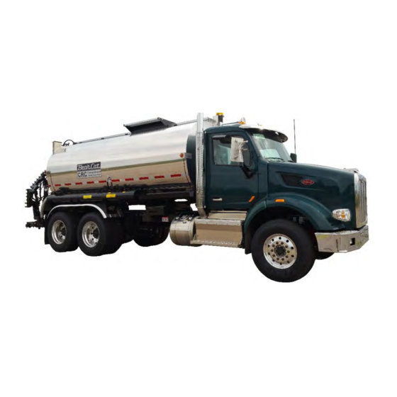
Equipment Description The Model BC-502/CRC Cab Operated Computer Controlled Liquid Asphalt Distributor is pictured below. The following description of the equipment should be read to familiarize yourself with the operating features and capabilities of the Model BC-502/CRC asphalt distributor. -
Page 18: Hydraulics
BC-502/CRC Hydraulics Pump Drive Options Hydraulic power is used to drive the asphalt pump and move the spray bar. Primary power for the hydraulic system is derived from a power takeoff driven by the truck engine. Either a transmission PTO, Crankshaft, REPTO, or an additional engine may be employed. -
Page 19: Hydraulic Reservoir And Filter
Additional Engine The additional engine option uses an engine mounted to the distributor body to power the hydraulic system. The additional engine has the hydraulic pumps direct mounted and is used primarily for applications where the truck PTO or crank drive is not feasible or the horse power required is in excess of truck engine capabilities. - Page 20 BC-502/CRC any truck speed. While in CRC, the system monitors the vehicle speed and determines the proper pump parameters to maintain the selected gallons per square yard (GSY) of asphalt distribution. Automatic control occurs only when the selector on the cab Console is in the ‘CRC’ position.
-
Page 21: Hydrostatic Motor
Hydrostatic Motor The Hydrostatic Motor is a fixed displacement type motor that is driven by the hydrostatic pump through high-pressure hydraulic lines. The motor responds instantaneously to changes in either the speed or direction of the pump. The system is equipped with an integral relief valve that opens if the maximum rated pressure is exceeded, as may occur if the asphalt is frozen or the asphalt pump attempts to force asphalt against a closed valve. -
Page 22: Asphalt Plumbing
BC-502/CRC Asphalt Plumbing Asphalt Pump The Asphalt Pump is a positive displacement geared pump. The standard pump has a delivery capacity of 400 gallons per minute (GPM), BC-450 (4” x 400 GPM). The intake and outlet ports are of 4 inch (102 mm) diameter. -
Page 23: Auxiliary Hydraulic System
open spray nozzles or the travel speed of the asphalt distributor. The pump is capable of pumping any bituminous material at temperatures up to 400°F (204°C). The pump is easily accessible at the rear of the truck. The standard pump is equipped with a conventional stuffing box or packed seal. -
Page 24: Spray Bar
BC-502/CRC Spray Bar The spray bar used on the Model BC-502/ CRC distributor is a full circulation type spray bar. The spray bar permits circulation of asphalt throughout the entire interior of the bar structure. This configuration allows the fully... -
Page 25: Circulation Control
Circulation Control The spray bar contains two pressure-equalizing valves, one located at each end of the main bar just inboard of the wing swing joint. A third equalizer valve is located in the transverse pipe connecting the two spray bar flexible feed lines. -
Page 26: Wing Shear Pins
BC-502/CRC Wing Shear Pins Replaceable shear pins are used to assure correct alignment of the wings with the main bar. The shear pins act as a safeguard in the event that the wing strikes an object while in motion. On impact, the shear pin will break, thereby protecting the wing mechanism. -
Page 27: Controls
Controls Cab Console The operation of the Model BC-502 /CRC distributor can be controlled from the driver’s seat of the truck through the Cab Console. The following functions are controlled with switches on the panel: Cab Console • Power on •... -
Page 28: Side Control Panel
BC-502/CRC • Taper Cut Nozzle Cut Control • Valve Selector Switch • Computerized Rate Control (CRC) and Manual with system monitor A master switch is provided for the purpose of simultaneously opening or closing all spray valves for which the individual switches are in the on position. -
Page 29: Computerized Rate Control (Crc) System
Computerized Rate Control (CRC) System The BearCat Computerized Rate Control System is installed on Model BC-502/CRC distributors as standard equipment. The CRC System automatically holds the spread rate at the selected application regardless of truck speed or gearing, in forward or reverse or during mid pass changes in spray bar width. -
Page 30: Spray Bar Flushing System
Hand Wand and Hose Reel Pattern Spray Capability As described previously, the spray valves in the standard BearCat spray bar can be opened and closed in one foot increments utilizing the in-cab control panel switches. One foot consists of three individual valves or one Tri-Valve group. -
Page 31: Remote Curb Side Mirror
Remote Curb side Mirror The remote curb side mirror can be positioned from the driver’s seat to show the normal field of view for highway travel, or adjusted to view the curb side wing extension and the space adjacent to the truck. The mirror position is controlled through switches on the Cab Console. -
Page 32: Specifications
Standard Rubber Feed Hose ........ Intermittently 350°F (177°C) Optional Stainless Steel Feed Hose ..........450°F (232°C) Asphalt Handling Functions: Load through spray bar, Off-load, Transfer, Circulate, Heat, Spray, Flush. BearCat Asphalt Pump Type ................Positive Displacement Internal Pressure Relief ................70 PSI Standard Capacity ............400 Gallons Per Minute Spray Bar Seals Standard ............High Temperature Shaft Packing... - Page 33 Position Control: Maximum Height ................20in (51cm) Minimum Height ................10in (15cm) Total Side Shift ...............26in (66cm) Wing Lift ........................ 90° Spray Control Increments: Standard .................... 1ft (30cm) Control ................... Console Switches Spray Nozzle Valves Type ....................... Poppet Center-to-Center Spacing ..............4in (10cm) Actuation ............
- Page 34 BC-502/CRC COMPUTERIZED RATE CONTROL SYSTEM Data Displays Gallons per Square Yard Feet per Minute Gallons per Minute Spray Bar Width Distance Traveled Nozzle Size Gallons Used Asphalt Screens Load Screen ...............1/4in (6.4mm) mesh Spray bar Screen ..............3/32in (2.4mm) mesh Construction ..................Cylindrical External Wash-down/Flush Tank ..................8 Gallons Pressurized...
- Page 35 Internal Crawl Holes ............... 20in (51cm) Jacket ..................0.040 Aluminum Vent ....................2in (5cm) Overflow Drain ................3in (7.6cm) Mounting ......Single Blade Bolster; Resilient Attachment to Truck Grip-Strut Catwalk ................22in (51cm) Optional Curb Side Remote Mirror Size ............9in Wide X 16in High (23cm X 41cm) Movements ..............Up &...
-
Page 36: Safety Precautions
BC-502/CRC SAFETY PRECAUTIONS Personnel Safety The safety of personnel working with or near the equipment depends on careful observance of the precautions and protective measures in this section. WARNING: THE MATERIALS USED IN THE TRANSPORT ARE NORMALLY HEATED TO 300° F TO 400° F DURING APPLICATION. - Page 37 WARNING: EXTREME CARE MUST BE USED WHEN CHANGING AN ASPHALT TANK FROM WET ASPHALT TO HOT ASPHALT. FAILURE TO FOLLOW THE PROPER PROCEDURES COULD CREATE A POTENTIAL STEAM EXPLOSION HAZARD, RESULTING IN SEVERE BURNS, INJURY OR DEATH. WARNING: POTENTIAL EXPLOSIVE/FIRE HAZARD CONDITIONS WARNING: FAILURE TO COMPLY WITH THE FOLLOWING LIST OF SAFETY RULES COULD RESULT IN A FIRE OR...
-
Page 38: Pumping Operations
Pumping Operations BC-502/CRC WARNING: WORN OR FAULTY HOSES CAN BURST AND CAUSE SEVERE BURNS, SERIOUS INJURY OR DEATH. CHECK CONDITION OF ALL HOSES BEFORE OPERATING. • ALWAYS wear a face shield when pumping hot asphalt. • ALWAYS check the condition of the transfer hoses before beginning pumping operations. -
Page 39: Burner Operations
Burner Operations WARNING: POTENTIAL FIRE OR EXPLOSION HAZARDS EXIST WHEN OPERATING THE BURNERS. FAILURE TO FOLLOW THE BURN OPERATION SAFETY PROCEDURES COULD RESULT IN SEVERE BURNS, INJURY OR DEATH. • Locate and inspect the condition of your Fire Extinguisher • ALWAYS use the auto ignition switch or a hand torch to ignite a burner. - Page 40 BC-502/CRC When using dual burners: • ALWAYS ignite the inside burner (lower burner) first. • In the event it becomes necessary to re-ignite the inside burner, NEVER reach across a lit burner to re- ignite an inside burner. • ALWAYS allow the flues to ventilate for a least two (2) minutes before re-igniting a burner that has gone out.
-
Page 41: Clean The Equipment
Never operate the equipment with a safety decal or plate that is hard to read or is missing. • The following diagram shows the location and part numbers of all safety decals. • Please contact BearCat for replacement decals at: Phone: (928) 684-7851 service@bearcatmfg.com... - Page 42 BC-502/CRC...
-
Page 44: General Operation
This Section contains information with which the operator must be familiar in order to prepare the Model BC-502/CRC distributor for spraying operations. Five essential areas are covered. Operating controls, gages, and indicators •... -
Page 45: Controls
Familiarity with these areas of activity will prepare the operator for efficient, safe operation of the equipment. To understand how the equipment at the rear of the BearCat equipment works, the operator should first operate the rear control panel functions before operating from the front control panel. -
Page 46: Operator's Panel, In Cab
Front opens valve “G” and Rear opens valve “C”. Power Main power switch for BearCat Distributor – nothing at the rear works until this switch is on. If it has been turned off and then back on, certain functions (Master, Pump, and PTO) will have to be re-set. -
Page 47: Error
Indicator light for possible malfunction or operation of equipment beyond capabilities. NOTE: To understand how the equipment at the rear of the BearCat equipment works, the operator should first operate the rear control panel functions before operating from the front cab console. -
Page 48: Spray Valve Switches Left Wing
BC-502/CRC WARNING: IF THE MASTER SWITCH AND ANY SECTION SWITCH IS TURNED ON WHEN LOWERING A WING, THE WING WILL TURN ON (SPRAY). THIS COULD RESULT IN SEVERE BURNS, SERIOUS INJURY OR DEATH. WARNING: MAKE SURE ALL PERSONNEL ARE CLEAR OF THE REAR AREA OF THE TRUCK WHEN THE WINGS OR THE SPRAY BAR ARE ACTUATED. -
Page 49: Taper Cut
Taper Cut Two switches incrementally cut-off or turn-on spray bar nozzles each time the switch is pressed. The left switch starts at left end of left wing and cuts in and back out. The right switch starts at right end of right wing and cuts in and back out. -
Page 50: Display
BC-502/CRC Display GSY FPM GPM Width- where GSY = spread rate in gallons per square yard as presently entered into the CRC system; FPM = vehicle speed in feet per minute; GPM = asphalt pump flow rate in gallons per minute; and Width = spray bar width in feet, as determined by the setting of the control panel spray bar switches. -
Page 51: Pump Direction
Pump direction When switched Forward, the pump flows in the bottom and out the top. When switched Reverse, the pump flows in the top and out the bottom. In the center position, the pump is stopped. Manual Increase Speed Turning the knob clockwise increases the pump speed. To avoid pump or hose damage, start every manual pumping operation with the speed control at zero (fully ccw) and increase the speed slowly while observing the pump and hoses. -
Page 52: Lh & Rh Wing Locks
BC-502/CRC LH & RH Wing Locks Press and hold rubber coated momentary switches to unlock the wing locks to lower wings. Wing locks automatically engage when the inner wing is raised completely. L. Wing & R. Wing #1: This raises and lowers the wing section next to the main spray bar. -
Page 53: Burner
L. Burner This operates the same as the “Right Burner”, but will not operate without the right burner turned on. a. Check material in product tank covers tubes by 6” or more. b. Open exhaust stack lid. c. Turn on right or lower burner. d. -
Page 54: Asphalt Valve Locations And Functions
BC-502/CRC Asphalt Valve Locations and Functions Valve Locations A. Intake from external source with pump in FORWARD. Gravity unload. B. Pump Isolation (optional). C. Main Tank Valve (rear). D. External Discharge with pump in FORWARD. Intake from external source with pump in REVERSE. - Page 55 Flush Return K. Spread Circulate (Bypass) L. Trough Mounted Side Load (Optional) M. Hand Wand Supply Study the layout of the valve locations. This plumbing diagram will be used throughout the manual to reference different circulation paths. Notice the difference between the closed valves (previous page) and the open valves in the circuit.
-
Page 56: Asphalt Tank Gauge
BC-502/CRC Asphalt Tank Gauge The amount of material in the tank is shown on a flotation gauge mounted on the driver’s side of the tank. The gauge is marked in 50 gallon increments. NOTE: The vehicle must be stationary and level to obtain an... -
Page 57: Asphalt Temperature Gauge
When the desired rate of travel in feet per minute and the required spread rate in gallons per square yard are known, the appropriate nozzle size can be selected with the aid of the BearCat Road Oil Spreading Calculator, which is furnished with the Model BC-502 /CRC distributor. If the nozzles presently in the spray bar are not of a suitable size, change them according to the instructions given below. -
Page 58: Spray Nozzle Removal And Installation
BC-502/CRC Slide Calculator Spray Nozzle Removal and Installation To remove or install nozzles, use the wrench provided with the asphalt distributor. The wrench is equipped with a folding stop that should touch the adjacent nozzle in the spray bar when the nozzle being installed is properly aligned. -
Page 59: Check Hydraulic Controls
Check Hydraulic Controls: a. Observe the sight glass on the hydraulic reservoir. Some fluid should be visible when the system is cold. If fluid is required, use Type 46 Hydraulic Fluid. b. Start engine, run at idle, Power up Console. Hydraulic Reservoir and Filter c. -
Page 60: Flushing Tank
The tank can be loaded by any of the seven methods as described. WARNING: TO AVOID POTENTIAL SEVERE BURNS, SERIOUS INJURY OR DEATH, PERSONNEL MUST READ SECTION 2 (SAFETY PRECAUTIONS) BEFORE OPERATING BEARCAT EQUIPMENT WARNING: EXTREME CARE MUST BE USED WHEN CHANGING AN ASPHALT DISTRIBUTOR FROM WET ASPHALT TO HOT ASPHALT. - Page 61 The most dangerous situation is to begin circulation of a “wet” spray bar into a full tank of hot asphalt. Spray bar circulation forces the material in the spray bar into the bottom of the tank. If the material is water-based (emulsified asphalt), the hot asphalt in the tank changes the water to instant steam.
- Page 62 BC-502/CRC e. On the Side Control Panel, select and perform “On Load Thru Spray bar Hose A”. Load the tank slowly (40 GPM) with enough material to cover the heat tubes. On the Cab Console, select “Spread-Heat” and circulate the spray bar for 10-30 minutes.
-
Page 63: Loading Tank
Loading Tank Loading Through Valve A This method is the fastest and simplest way to load asphalt into the tank. WARNING: EXTREME CARE MUST BE USED DURING PUMPING OPERATIONS TO MAKE SURE THAT SYSTEM COMPONENTS OPERATE AT THEIR RATED PRESSURES AND TEMPERATURES. - Page 64 BC-502/CRC b. On Side Control Panel, Select, “On Load Hose-A” and pull “Pump/Valves” (red button) to actuate “F” valve. c. With pump in “Forward”, slowly turn the Manual Increase dial clockwise to ¼ turn or approximately (40-60 GPM). While observing all connections and the transfer hose, open the “A”...
-
Page 65: Loading Through Optional Valve L
e. Loosen the connection at the supply vessel so it will draw in air to suck the hose clear. Do this for three minutes and then remove the hose from the supply vessel, elevating it to help clean it. If you wish, draw some diesel through the hose to help clean it. Close Valve A. -
Page 66: On Load Thru Spray Bar
BC-502/CRC On Load Thru Spray Bar Loading thru spray bar is safest method for loading hot asphalt into a wet or potentially wet tank. This method is also useful when it is necessary to keep the material in the bar from freezing, as may occur when handling paving grade asphalt in cool weather. - Page 67 Open valve A g. While observing the hose and the connections, Open supply valve. h. If all is well, increase the pump speed to a maximum of 150 gallons per minute. The pump will push asphalt through the spray bar and into the tank. When the desired amount of asphalt has been pumped, close supply valve.
-
Page 68: Loading Through Manhole
BC-502/CRC o. On the Cab Console, select “Spread Heat” and “Pump FWD” to resume spray bar circulation Loading Through Manhole WARNING: EXTREME CARE MUST BE USED WHEN OPENING MANHOLE COVER TO PREVENT ESCAPING HOT GASES FROM CONTACTING THE OPERATOR. A FACE SHIELD AND GLOVES MUST BE WORN. -
Page 70: Off Load Thru Valve D
BC-502/CRC OFF Load Thru Valve D WARNING: EXTREME CARE MUST BE USED DURING PUMPING OPERATIONS TO MAKE SURE THAT SYSTEM COMPONENTS OPERATE AT THEIR RATED PRESSURES. FAILURE TO CHECK THE CONDITION OF ALL HOSES AND CONNECTIONS WHEN PUMPING COULD RESULT IN SEVERE BURNS, SERIOUS INJURY OR DEATH. - Page 71 k. Loosen the connection at the supply vessel so it will draw in air to suck the hose clear. Do this for three minutes and then remove the hose from the supply vessel, elevating it to help clean it. If you wish, draw some diesel through the hose to help clean it.
-
Page 72: Through Pump Transfer
BC-502/CRC Through Pump Transfer CAUTION: INSPECT THE INTEGRITY OF HOSES AND FITTINGS. DO NOT TRANSFER ASPHALT WITH A FAULTY HOSE OR FITTINGS. a. Connect feed hose between Valve A, and the supply tank valve. b. Connect feed hose between Valve D, and the Transfer tank valve. - Page 73 If all is well, increase the pump speed to a maximum of 150 gallons per minute. The pump will pull asphalt from the Supply Tank and push it to the Transfer tank. When the desired amount of asphalt has been pumped, close supply valve.
-
Page 74: Gravity Off Load (External Pump Transfer)
BC-502/CRC z. On the Cab Console Select Auto Flush then switch Pump to FWD. Gravity OFF Load (External Pump Transfer) a. Connect transfer hose (inspect condition) from supply vessel to Valve A. b. On Side Control Panel, Select Gravity OFF Load and pull “Pump/ Valves”... -
Page 75: Heating Asphalt
g. Loosen the connection at valve A so it will draw in air to suck the hose clear. Do this for three minutes and then remove the hose from the supply vessel, elevating it to help clean it. If you wish, draw some diesel through the hose to help clean it. Heating Asphalt NOTE: Before starting the heaters, position the vehicle broadside to the... -
Page 76: Tank Circulation While Heating
BC-502/CRC • ALWAYS use the auto ignition switch or a hand torch to ignite a burner. NEVER use a match or lighter, • ALWAYS make sure flues are covered by at least 6- inches (152 mm) of material before heating, •... -
Page 77: Cold Asphalt (Too Stiff To Circulate)
Cold Asphalt (too stiff to circulate) a. Check the parking brake is set and the asphalt tank gauge reads above the fire line. b. Open exhaust stack. c. Start burners as needed. d. Monitor temperature to circulate as soon as possible. e. - Page 78 BC-502/CRC a. Open lids on top of exhaust stacks. b. Make sure MASTER switch is off. c. Turn R. or LOWER BURNER switch ON. Burner will ignite automatically. d. Turn L. or UPPER BURNER switch ON. e. Monitor the temperature gauge. Do not allow the asphalt...
-
Page 79: Operating Instructions
DURING EQUIPMENT OPERATION. ONLY QUALIFIED PERSONNEL SHOULD ATTEMPT TO OPERATE, SERVICE OR MAKE ADJUSTMENTS TO THE BEARCAT EQUIPMENT. a. At job the site, with the engine idling, turn cab console power switch on. With control panel turned on, the display will show a Warning. - Page 80 BC-502/CRC n. start line. (This might take a little practice). o. During the shot, you may increase or decrease speed, you may also change bar width, you can also change spread rate. You must however, monitor the GPM as to not over-speed the pump’s capability;...
-
Page 81: Spraying Operations Using The Optional Front Suction
Spraying Operations using the optional Front Suction With the optional Front Suction or “G” valve, you can spread while spraying down a steep incline. The G valve draws from the (bottom front) of the tank. With this option there is a switch on the Cab Console labeled Front Suction, choose Front or Rear. -
Page 82: Setting Spread Rate Manually
BC-502/CRC Setting Spread Rate Manually a. Use the BearCat Road Oil Spreading Calculator to set the spread rate manually. b. Determine the job requirement. For this example, we will assume it to be 0.4 gallon per square yard (GSY), to be spread over an area 12 feet wide and 1300 feet long. -
Page 83: Hand Spraying While Circulating Spray Bar
Use the Taper Cut switches to select the same spray valves on the display. m. With the transmission in neutral, hold the engine RPM at the pre- determined RPM to maintain 400 FPM. With the GSY Switch, select the desired GPM (215 GPM) on the display. n. -
Page 84: Hand Spraying
BC-502/CRC Close Valve M. m. On Cab Console return Pump to FOR. n. Switch to CRC. Hand Spraying a. On the Cab Console, select Load Outside. b. Remove Hand Wand and uncoil needed amount of hose. c. On the Side Control Panel, select OFF Load Hose D. - Page 85 d. Pull Pump/Valves (red button) to actuate valve C (DO NOT Open Valve D). e. Switch Pump to Forward. Turn Manual Increase speed CW from zero about 1/8 turn or until pump starts to rotate about 10 GPM. g. Open valve M. Open Hand Wand Handle Valve to spray.
-
Page 86: Spray Bar Flushing
BC-502/CRC q. Switch Pump to Neutral Spray Bar Flushing 1. Check Flush Tank fluid level 2. With spray bar warm and circulating… a. Check Master Switch OFF. b. Switch Pump OFF. c. Select Auto Flush. d. Switch Pump FWD. Display should indicate GPM. -
Page 87: Stage 1
Stage 1... -
Page 88: Stage 3
BC-502/CRC Uses forced air to push asphalt from Spray bar back to Tank. This process automatically actuates valves E, I, and K, and runs the pump at high speed to evacuate the system. After 5 minutes of purging the system switches to stage 2. -
Page 89: Empty Flush Tank
Actuates valves I, E, and J, purging the Spray bar of flush fluid with forced air from 40 GPM increasing to high speed. After 5 minutes the cycle is finished, all valves close and the Pump Stops. The Auto Flush is finished. - Page 90 BC-502/CRC d. Switch Pump Forward. e. Turn Manual Increase Speed dial to ½ turn (about 100 GPM). Cycle about 5 Minutes and push red button to stop. g. Zero Manual Increase Speed dial. h. Switch Pump to Neutral. Refill Flush Tank.
-
Page 91: Shutting The Equipment Down
Shutting the Equipment Down After Completing the Spray bar Flushing Procedure (Auto Flush), a. On the Cab Console select OFF with the Valve Selector Dial. b. Switch Pump to OFF c. Center the spray bar and raise it to the maximum height. Engage the latches to lock it in place. -
Page 92: Console Display
BC-502/CRC Power the Cab Console OFF CONSOLE DISPLAY Start Up Press and hold the Power switch up until the screen lights up then release the switch. After a few seconds a warning will display. It is important to read and understand the condition of your truck. - Page 93 your spray bar and plumbing is wet, circulating the spray bar will cause an eruption. Tank eruptions can blow tanks apart killing people and creating a huge mess. If you are in a situation with a loaded tank of hot asphalt and are unsure of the condition of the spray bar or know it is wet, use another truck to off-load the tank or take it back to the plant and off-load.
-
Page 94: Home Page
BC-502/CRC The upper right green light indicates Manual Operation and/or Simulate FPM is on. The large Error light to the right of the Display also comes on when either of the small red lights come on to alert the operator. -
Page 95: Pto
(Power Take Off) Turns green when engaged or on. Asphalt pump speed is measured in Gallons Per Minute. When ever the pump is turning forward or reverse, manually or in CRC, GPM is indicated. A sensor mounted in the hydraulic motor picks up the pump speed. -
Page 96: Gallons
BC-502/CRC Notice that all the Spray Valve switches are turned on, yet the Width indicates 9 ft. The Taper Cut has been deselected or turned OFF from the left on the display. The same result in width can happen if all the Taper Cuts are ON but the Spray Valve switches are OFF. -
Page 97: Feet
Press Select until Gallons Used is highlighted, then press and hold reset to zero the counter. Feet In the left window, distance is measured when the Master switch is turned On. This measurement is reset every time the Master switch is Sq. -
Page 98: Settings Menu
BC-502/CRC Settings Menu From the Home Page press the Next button to access the Settings Menu. Next and Back buttons are for changing pages. Buttons at the left lead to additional setting pages. Use Select to highlight each button for a description of the settings associated with the highlighted button. -
Page 99: Simulate Fpm
simply selecting Manual with the Manual/CRC switch the Console. Use GSY Inc/Dec to change speed. Having the ManPump setting pre- set to 100-150 GPM, help in the event of plugged Poppet valve or Spray bar collision damage. Simply switch to Manual and reverse pump to suck back Spray bar and stop... -
Page 100: Flush Time
BC-502/CRC Flush Time During the Flush cycle, there are 3 processes. 1. Flush Cycle 1 (purges asphalt from the spray bar). 2. Flush Cycle 2 (circulates solvent from the Flush Tank thru the spray bar and back to Flush Tank). During this cycle the spray valves can be operated if desired. -
Page 101: G-Cal
(gallons/(length x width)). In order for the machine to spread accurately it must be calibrated accurately. 1. On a smooth straight surface, accurately tape measure a distance of 1000 ft. Mark the start and finish so they are visible from the cab of the distributor. 2. - Page 102 BC-502/CRC (Gallons Calibration) is used to calibrate the pump for compensation in pump wear or variables in material viscosity. The pump is used as a meter to control the amount of material applied. Each revolution of the pump delivers a calculated amount of product.
-
Page 103: T-Cal
Press OK to save and exit. g. Press Next or Back to return to the Home Page and adjust the Spread Rate to the desired amount. h. Making G-Cal adjustments on longer shots will have a more accurate effect. Also calculating spread rate on longer shots is more accurate. -
Page 104: Pump
BC-502/CRC through per-programed options like Augers, Vertical mixers, Sweep Mixer, etc. Pump A factory setting for selecting pump size, style and configuration. Select and Edit, then use Up & Down to cycle through pre-programed options like 300, 450, 600, 960, and meter combinations. -
Page 105: Spray Bar
Spray Bar A factory setting for the spray bar setup based on build options. On the Settings menu, Press the Select button to highlight “Spray Bar”. A preview of the available settings is shown. Press OK to enter the page. Spray bar Settings Factory settings page used in the initial setup of the spray bar or if any changes are made to the... - Page 106 BC-502/CRC Live Extensions are included in the Width Setting and are controlled in sequence with permanent mounted Spray Valve Sections. Dummy Extensions that are controlled by other spray valve sections need to be included in the width calculation in order for the spread rate to calculate correctly.
-
Page 107: Tank
Tank On the Settings menu, Press the Select button to highlight “Tank”. A preview of the available settings is shown. An optional setting for a tank gauge sender mounted on the tank that displays the gauge or (gallons) level on the Console Display. -
Page 108: Volts/Snsr
BC-502/CRC and instructions will appear in the description box. Press OK to enter the page. Volts/Snsr Various sensor and volt readings at designated Pin locations are displayed. The Pin numbers refer to pins in the wiring harness on particular plugs or connectors. The wiring schematic will be needed to locate the connector or sensor. -
Page 109: Switches
Switches Select and OK to enter the switch diagnostic page. Represented on this page is a switch from every option available (there may be switches you don’t have). The switch on the screen or display should act just like the mechanical switch on the Console. -
Page 110: Rear Ctrl
BC-502/CRC Rear Ctrl Select and OK to enter the Rear Control Panel Switch diagnostic page. Again the input voltage and sensor output voltage are displayed in upper area of back. If you turn a switch on or off the switch on the display should mimic the same movement. -
Page 111: Pump Test
Pump Test Select to read the description of each Test scenario. The standard Safety lockout sequence will inhibit the execution of the test unless (Master Off, Select Switch Off, Pump Neutral). Press OK to engage, then with the Selector Switch, select Spread Heat and Pump direction. Returning the Selector switch to Off will cancel the test as well as Power Off. - Page 112 BC-502/CRC Pump T-4 Meter material from the tank (C valve), thru the pump and out the (D Valve). Based on FPM (if moving), Spread Rate and Bar width. Pump circulates thru F with Master Off. a. Connect asphalt hose from the external spray bar to the D valve, and open pertaining valves.
-
Page 113: Spraying Complex Patterns
SPRAYING COMPLEX PATTERNS Any number of patterns or shapes can be sprayed quickly and accurately, using a minimum of handwork, when the Model BC502/CRC distributor is employed properly. Two ingredients are essential for the successful completion of a complex spray operation: The operator must be thoroughly familiar with the Model BC502/CRC operating controls. - Page 114 BC-502/CRC Step 1. To outline a central clear area, the truck is first driven diagonally across the parking area in two passes: first with both marker valves open, and again with only the left hand marker valve open. The result is a defined area of twice the width of the spray...
- Page 115 Step 2. The truck is driven around the left hand portion of the curbed perimeter with only the left wing spray valves open. The spaces at the entrance and exit are left unsprayed. NOTE: More satisfactory lines with the line markers may be obtained by turning the pump off.
- Page 116 BC-502/CRC Step 3. The truck is positioned parallel to the left hand curb at the entrance area. As the vehicle is moved forward, spray valve switches are turned on to produce the pattern shown. When the farther section of the...
- Page 117 Step 4. The truck is driven along the central clear area with one wing projecting over the edge of the area sprayed on in Step 5. The wing spray valves are switched on and off as needed to produce the pattern shown. The result is a straight edge along the clear area.
- Page 118 BC-502/CRC Step 5. Steps 2 through 4 are repeated on the right hand side of the area to produce the pattern shown.
- Page 119 Step 6. The right half of the central clear area is sprayed in one pass from the exit end. Recall that the clear area was made twice the full width of the spray bar.
- Page 120 BC-502/CRC Step 7. Finally, the remaining half of the central area is sprayed in a single pass from the entrance to the exit. The entire area can now be spread with chips.
-
Page 121: T - Intersection
T - Intersection T - intersection at which the job requirement is to coat the secondary road up to the line where it joins the primary. The chip spreader is instructed to stop at the dashed line and hold there until the intersection has been sprayed. - Page 122 BC-502/CRC Step 2. The left hand and right hand corner areas are sprayed. As the truck is driven through the arcs, spray valve switches are turned on and off as needed to produce the patterns shown. Step 3. The irregular edges along the lines BC and FA are sprayed. The truck is driven along the primary road with only as many wing spray valves open as are needed to make a smooth edge.
- Page 123 Step 4. The truck is backed into position to spray the left hand portion of the secondary road, starting at the dashed line that marks the termination of the previous work. (If any hand spraying along the line DC is required, it should be completed first.) Step 5.
- Page 124 This Section contains procedures that have been developed through experience with asphalt distributors under a wide variety of working conditions. Users of BearCat asphalt distributors will find these procedures helpful and time saving. BearCat users who develop techniques to improve the efficiency of the spreading operation are encouraged to report these techniques.
- Page 125 When backing the vehicle to connect with an area that has already been sprayed, it is common for the truck to be at a slight angle relative to the line of the existing spray. To continue the required pattern, the operator must make a steering correction immediately when beginning the new spray run.
-
Page 126: Field Maintenance
BC-502/CRC FIELD MAINTENANCE Overall productivity of the asphalt distributor can be increased and equipment downtime minimized by carefully following the procedures given in this Section. Regular flushing of the spray bar is especially important to avoid the time-consuming process of clearing a bar plugged with frozen asphalt. -
Page 127: Alternate Method: Clearing With A Torch
Alternate Method: Clearing with a Torch WARNING: CLEARING A SPRAY BAR WITH A TORCH CREATES A POTENTIAL FIRE HAZARD. TO AVOID SEVERE BURNS, INJURY OR DEATH DO NOT BEGIN THIS PROCEDURE WITHOUT A DRY CHEMICAL FIRE EXTINGUISHER AVAILABLE. MAKE SURE THAT THE TORCH FLAME IS KEPT WELL AWAY FROM ALL HOSES AND AIR CYLINDER a. -
Page 128: Clean Bar Screen
BC-502/CRC b. Ensure valves C and B are closed. c. Remove the four nuts at the corners of the cover plate immediately behind Valve A. d. Remove the four lugs and take off Valve A. e. Pull out the cylindrical screen and remove the material collected on it. -
Page 129: Seal Replacement
In pumps equipped with the optional low maintenance shaft seals, two seals are located where the pump shaft connects to the drive shaft from the hydrostatic motor. These seals should be replaced if leakage appears. Replacement seals are available from BearCat Mfg. -
Page 130: Replace Nozzle Valve Stem Seals
Remove the O-ring and the seal and discard them. g. For this and the following steps, use the two piece seating tool (available from BearCat; P/N MSC-27280 and MSC-27281). Place the shorter seating tool in the valve seat on top of the spray bar. -
Page 131: Adjust Actuators For Spray Nozzle Valves (Mechanical Linkage)
Put a few drops of light oil around the inner surface of the tool. This component of the tool may require grinding to enable it to clear the edge of the square tube valve lifter. h. Place the new seal on the longer tool. With the seal lips toward the spray bar, push the tool down inside the shorter tool until the seal is seated. - Page 132 BC-502/CRC d. If valve stem travel is more or less than 1/16”, heat the control lever (connected to pneumatic cylinder actuator rod) with a torch and bend it until the proper travel is established. e. When the center valve has been properly positioned check the two remaining valves of the set.
-
Page 133: Adjust Remote Curbside Mirror
Adjust Remote Curbside Mirror The adjustable stops that position the mirror are located as follows: UP: Upper of the two adjustable bolts located on the support bracket fastened to the back of the mirror. DOWN: Lower of the two adjustable bolts located on the support bracket fastened to the back of the mirror. -
Page 134: Removal Of Spray Bar
Removal of Spray Bar If the spreader assembly must be removed to free the vehicle for other uses, consult the BearCat Mfg. Service Department (telephone (928) 684- 7851) before proceeding. Hydraulic System Maintenance The hydraulic system must be serviced at the beginning of each working season. -
Page 135: Cargo Pump Operation
Cargo Pump Operation The direction of rotation of the gears determines which port will function as the inlet and with is the outlet. Recall the rule of cargo pump operations: FWD = IN at bottom, OUT at top REV = IN at top, OUT at bottom The cargo pump operates on the positive displacement principal. -
Page 136: Crc System Calibration And Service Adjustments
MANUFACTURER AND SHOULD NEVER REQUIRE MODIFICATION. IF SYSTEM PERFORMANCE INDICATES THAT CALIBRATION IS NECESSARY, CONTACT THE BEARCAT SERVICE DEPARTMENT BEFORE PROCEEDING WITH ANY CALIBRATION OR ADJUSTMENT. To change the calibration and default values, proceed as follows: a. On the Console Display press “next” until you reach the Settings Menu. - Page 137 K Valve (spread circulate) or “bypass valve” When the Master switch is turned on, a pneumatic valve in the rear control box supplies air through a pre-set 60 psi regulator to a diaphragm cylinder which presses down on a disk to close the spread circulate line. Sometimes a piece of coke or hard contaminate can stick to the seat of the disk.
- Page 138 BC-502/CRC With a piece of wire or screwdriver, lift out disk. Clean and inspect the disk seat. The surface should be smooth and clear of debris. Also inspect the valve seat inside for similar problems. Some emulsions and corrosive products can cause pitting which will result in valve replacement.
- Page 139 Troubleshooting SYMPTOM POSSIBLE CAUSE SOLUTION Does not achieve Clogged filter screens. Clean both the suction and proper spread rate bar filter screens per Malfunction in instructions in the Field equalizer valve. Maintenance section of this Malfunction in asphalt manual. pump relief valve (the Examine valve action to valve opens at less than verify that valve opens when...
- Page 140 BC-502/CRC Spray bar fails to Blockage in solenoid Actuate the valve manually complete operated hydraulic by pressing the plunger at commanded valve. each end of the valve with a motion (bar raise, small screwdriver. Lack of signal from bar shift, or wing...
- Page 141 For additional help on burner trouble shooting watch the Diesel Burner Repair Video. http://www.bearcatmfg.com/Video/DieselBurnerRepair/ DieselBurnerRepair.html If burner still fails to operate correctly contact BearCat’s Service Department. 928-684-7851 For additional assistance in troubleshooting or repairing your BearCat equipment, please contact us.
- Page 142 BC-502/CRC Preventive Maintenance Schedule The minimum recommended service checks and intervals for your asphalt distributor are as follows: Daily 1. Check hydraulic oil level (ISO 46). 2. Check filter vacuum gauge after initial warm up. 3. Check gland packing for leaks: a.
- Page 143 Monthly 1. Lube the cargo pump drive line (do not over grease). 2. Lube the PTO drive line or, if equipped, the crank drive line (do not over grease). 3. Check gear oil level in the hydraulic motor gear box (if applicable) 75W-140.
- Page 144 BC-502/CRC Bolt Torque Chart Torque specs in Foot Pounds with threads lubricated. SIZE GRADE 2 GRADE 5 GRADE 8 1/4-20 1/4-28 5/16-18 5/16-24 3/8-16 3/8-24 7/16-14 7/16-20 1/2-13 1/2-20 9/16-12 9/16-18 5/8-11 5/8-18 3/4-10 3/4-16 7/8-9 7/8-14 1-14 1 1/8-7...
- Page 145 Conversion Chart FPM ↔ mph 1 FPM = .0114 mph 1 mph = 88 FPM Miles ↔ Kilometers 1 Mile (5280’) = 1.609 km 1 km (1000m) = .62 Miles Miles ↔ Meters 1 Mile = 1609.3 m 1 km = 8500.8 ft Feet ↔...
- Page 146 PARTS Figure 1 Main Control Panel..........147 Figure 2 Main Panel Pedestal ..........147 Figure 3 Side Control Panel ..........147 Figure 4 Rear Control Panel ..........148 Figure 5 Valve Bank ............148 Figure 6 Burner ..............149 Figure 7 Flush Tank ............149 Figure 8 Mechanical Link Assembly (Option) ....149 Figure 9 Rear Assembly ...........149 Figure 10 Spraybar Assembly ...........150 Figure 11 Tri-Valve and Inner Wing Assembly ....150...
- Page 147 Figure 2 MAIN PANEL PEDESTAL 207045 CONTROL PANEL ID PART # DESCRIPTION 1 202823 SWITCH, ROTARY 207615 SIDE CONTROL PANEL 2 204067 READY LIGHT, RED ID PART # DESCRIPTION 3 207033 DECAL,BAR LATCH 1 101308 NODE 5, PROGRAMMED 4 ELC-24186 SWITCH, AIR TOGGLE 2 202823 SWITCH, ROTARY...
- Page 148 208092 REAR CONTROL PANEL ID PART # DESCRIPTION 1 200710 TERMINAL BLOCK SECT 2 201058 DEUTSCH 40 PIN PLUG 3 206356 FUSE BLOCK, 6 CIR 4 206357 FUSE, BLADE TYPE, 20 AMP 5 206359 FUSE, BLADE TYPE, 40 AMP 6 208005 PANEL, ENGRAVED, REAR CNT 7 4FP-4MJBH FITTING 8 ELC-24254...
- Page 149 Figure 7 FLUSH TANK Figure 9 REAR ASSEMBLY Figure 6 Figure 8 BURNER MECHANICAL LINKAGE ASSEMBLY...
- Page 150 Figure 12 REAR CONTROL ASSEMBLY Figure 11 Figure 10 TRI-VALVE & INNER WING ASSEMBLY SPRAYBAR ASSEMBLY...
- Page 151 Figure 14 HYDRAULIC SYSTEM Figure 13 INNER WING ASSEMBLY...
- Page 152 Figure 15 REAR PANEL ASSEMBLY...
- Page 153 PRODUCT TANK ID PART # DESCRIPTION 1 205881 NIPPLE, GROOVED 2 211771 BURNER ASY 3 BRK-21276 HOSE TROUGH 4 BRK-21482 BRACKET, FLUSH TANK 5 BRK-21485 BRACKET, FLUSH TNK, FENDER 6 BRK-23251A BRACKET, HOSE TROUGH 7 BRK-50552 ACTATOR ARM ASSY, TNK VLV 8 CYL-27323 CYLINDER, AIR, TANK VLV 9 FAS-27345...
- Page 154 Figure 17 PUMBING AND VALVE ASSEMBLY...
- Page 155 BAR MOUNT AND ACTUATION ASM ID PART # DESCRIPTION 31 GRD-52054 CAM LOCK BAR LATCH ASM 2 209752 CONDUIT, LIGHTS 32 204964 SUPPORT, RH WING 3 45D8MJ-6MP FITTING 33 206266 LIGHT, BACK UP LED 4" 4 90D8MJ-6MP FITTING 34 206277 LIGHT, S/T/T LED 4"...
- Page 156 Figure 19 PUMP DRIVE ASSEMBLY...
- Page 157 Figure 20 PRODUCT PUMP...
- Page 158 Figure 21 SIDE CONTROL BOX SCHEMATIC...
- Page 159 Figure 22 CAB CONSOLE SCHEMATIC...
- Page 160 Figure 23 VALVE BOX SCHEMATIC...
- Page 161 Figure 24 REAR CONTROL BOX SCHEMATIC...
- Page 162 Figure 25 REAR CONTROL BOX (PROPANE) SCHEMATIC...
- Page 163 Figure 26 HYDRAULIC LAYOUT...
- Page 164 Figure 27 HYDRAULIC SCHEMATIC...
Need help?
Do you have a question about the BC-502/CRC and is the answer not in the manual?
Questions and answers