
Related Manuals for DLG PHOTOMETER 2

Summary of Contents for DLG PHOTOMETER 2
- Page 1 Photometer 2 Instruction Manual DLGelectronics.com PHOTOMETER 2 Focal Plane Metering System Large Format Photography...
-
Page 2: Table Of Contents
Photometer 2 Instruction Manual DLGelectronics.com CONTENTS Introduction ........................3 Introduction to Focal Plane Exposure Metering .............. 4 Using the Photometer 2 ....................5 Technical And Performance Data ................10 Circuit Diagram ......................12 Warranty, Servicing, Repairs and Enquiries ..............13 Specification ........................ 14... -
Page 3: Introduction
The Photometer 2 provides image-plane metering at an affordable price in a simple, easy-to-use and robust metering system. The Photometer 2 comprises a metering unit, a frame (which is inserted in the camera in place of the film carrier) with integral metering probe, and a connecting lead. -
Page 4: Introduction To Focal Plane Exposure Metering
Photometer 2 Instruction Manual DLGelectronics.com INTRODUCTION TO FOCAL PLANE EXPOSURE METERING A photographic exposure meter measures lighting and indicates camera settings to give a nominally optimum exposure of the film. Several methods of metering are widely used. Reflected Light Metering... -
Page 5: Using The Photometer 2
Photometer 2 Instruction Manual DLGelectronics.com USING THE PHOTOMETER 2 Components of the Metering System The metering system comprises: The meter Frame, including rear shutter. Sensing probe Connecting cable. Insert 9V battery type - 6LR61 / 1604A / PP3. The battery compartment is on the rear of... - Page 6 Photometer 2 Instruction Manual DLGelectronics.com Insert the frame in the camera exactly as you would a film carrier. The metering frame is designed to the same geometry as a standard film carrier and should engage positively in the camera. The frame incorporates a slide shutter and this should be behind the metering probe, that is, it should come between the ground glass screen and the metering probe.
- Page 7 Photometer 2 Instruction Manual DLGelectronics.com Move the metering probe within the image to measure the brightness of the various features within the image. Adjust the “exposure” settings on the meter as required in order to keep the display within the required range. The display is marked in whole top numbers, so that e.g.
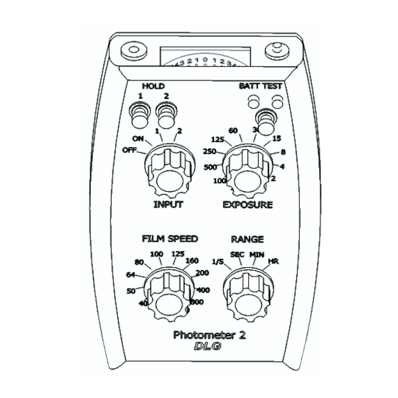
- Page 8 Photometer 2 Instruction Manual DLGelectronics.com Description of the Controls and Display Connection to metering Brightness probe indicator Display light push button Use the HOLD buttons to store the current brightness in memory 1 Push to test or memory 2. battery.
- Page 9 Photometer 2 Instruction Manual DLGelectronics.com selected exposure setting and film speed. Display pointer to the right indicates brighter whereas to the left indicates darker. When either of the “HOLD” positions is selected, the corresponding stored value is displayed. The HOLD functions memorise the brightness not the display – the displayed value is adjusted according to the settings of the exposure, range and film speed settings.
-
Page 10: Technical And Performance Data
Photometer 2 Instruction Manual DLGelectronics.com TECHNICAL AND PERFORMANCE DATA The information contained in this section is for guidance only and represents typical, rather than the guaranteed minimum performance. It is provided for the guidance of specialist users with unusual applications and may be disregarded by the majority of users. - Page 11 Photometer 2 Instruction Manual DLGelectronics.com Spectral Response Peak response is at 530nm (green). Response at extremes of the spectrum will be within a factor of two (one stop). In practice in normal situations, where highly saturated colours at the extremes of the visible spectrum are not normally present, no correction...
-
Page 12: Circuit Diagram
Photometer 2 Instruction Manual DLGelectronics.com CIRCUIT DIAGRAM Indicative only – component types and values may differ as part of our policy of continuous improvement... -
Page 13: Warranty, Servicing, Repairs And Enquiries
In the event of damage or defects, please contact us at enquiries@dlgelectronics.com, or write to us at DLG Electronics, 138 Osmaston Road, Derby DE1 2RF, UK, or contact your local distributor. For units outside warranty we can offer cost-effective repair, refurbishment or replacement with a refurbished model if you return your damaged unit. -
Page 14: Specification
Photometer 2 Instruction Manual DLGelectronics.com SPECIFICATION Exposure Range: 1/2000 second to 1 hour at 125 ASA Film Speed settings: 32, 40, 50, 64, 80. 100, 125, 160, 200, 400, 800, 1600 ASA (16, 17, 18, 19, 20, 21, 22, 23, 24, 27, 30, 33 DIN) Display Range ±... - Page 15 Photometer 2 Instruction Manual DLGelectronics.com...
Need help?
Do you have a question about the PHOTOMETER 2 and is the answer not in the manual?
Questions and answers