Table of Contents
Advertisement
INVOLAR Grid-Connected Photovoltaic
This manual is an integral part of the unit. Please read the instruction manual
carefully before installation, operation or maintenance. Keep this
instruction manual for future reference.
Tel: +86(0)02151098006
invo
Micro-Inverter
Model Number MAC500-XX
User Operating Manual
(Manual Version_1.12 MAC500-XX)
Fax: +86(0)2150277705
INVOLAR Corporation, Ltd.
2
E-mail:
info@INVOLAR.com
Web:
www.INVOLAR.com
Advertisement
Table of Contents

Related Manuals for Involar MAC500 Series

Summary of Contents for Involar MAC500 Series
- Page 1 INVOLAR Corporation, Ltd. invo INVOLAR Grid-Connected Photovoltaic Micro-Inverter Model Number MAC500-XX User Operating Manual (Manual Version_1.12 MAC500-XX) This manual is an integral part of the unit. Please read the instruction manual carefully before installation, operation or maintenance. Keep this instruction manual for future reference.
- Page 2 INVOLAR Corporation, Ltd. Contact Information INVOLAR Corporation Ltd Power Lab, No.898 Laiting South Road, Shanghai, 201615, China Tel: 86-21-5109 8006 Fax: 86-21-5027 7705 www.INVOLAR.com info@INVOLAR.com Manual version 1.12 INVOLAR Corporation Ltd. Mar. 2016...
-
Page 3: Table Of Contents
NDICATIONS AND RROR EPORTING ......36 INTERNET WEB ..............................39 EGISTRATION ......................... 39 OGIN ............................. 39 10 INVOLAR MAC500 MICRO-INVERTER TECHNICAL DATA ................40 ECHNICAL PECIFICATIONS ......................40 11 APPENDIX ................................42 IMITED ARRANTY ......................... 42 12. INVOLAR MAC500 M... -
Page 4: Read This First
To reduce the risk of electrical shock, and to ensure the safe installation and operation of the INVOLAR MAC500 Micro-Inverter, please read this manual carefully and pay attention to the safety symbols appear throughout this document. -
Page 5: Safety Symbols
INVOLAR Corporation, Ltd. 2 Safety Symbols Warnings and cautions tell you about the dangerous conditions thatmay occur if you do not follow all instructions in this manual. Please read following safety symbols which indicate dangerous conditions and important safety instruction. - Page 6 INVOLAR Corporation, Ltd. Symbols replace words on the equipment, on a display, or in manuals. Trademark No access for unauthorized personnel Caution, risk of danger Symbol marking electrical electronics devices according Directive 2002/96/EC. Indicates that the device, accessories and the packaging must not be disposed as unsorted municipal waste and must be collected separately at the end of the usage.
- Page 7 EMC and is authorized to energize, ground, and tag equipment, systems, and circuits in accordance with established safety procedures. The INVOLAR inverter system may only be commissioned and operated by competent personnel. Manual version 1.12 INVOLAR Corporation Ltd.
-
Page 8: Safety Instructionsand Ec Directives
Dangers, Warnings, Cautions or Instructions, contact the manufacturer or an authorized servicedealer before installing, operating and servicing the unit. For INVOLAR Micro-Inverter Warranty Terms and Conditions, see the appendix of this manual. SAVE THESE INSTRUCTIONS- This manual contains important instructions for the Manual version 1.12... - Page 9 INVOLAR Corporation, Ltd. MAC500 that shall be followed during installation and maintenance. Be aware that only competent personnel should install and /or replace INVOLAR Micro-Inverters. Perform all electrical installations in accordance with all local electrical codes. Compliance with the rules of correct use of tools and personal protective equipment (PPE) ensuring a safe installation.
- Page 10 INVOLAR Corporation, Ltd. WARNING Do not use fuseswhich are not approved by the manufacturer. They should be of same type and rating value as specified Only competent personsshould replace the fuse. AC fuse (F2,F3) Littelfuse 215; AC 250V, 3.15A, 5×20mm, rated...
- Page 11 INVOLAR Corporation, Ltd. DANGER This photovoltaic micro-inverter is only for use in a closed electrical operating area! The device shall not be energized during installation or maintenance! An internal isolation transformer is provided in the micro-inverter, internal transformer is galvanic isolation from the MAINS and PV array by reinforced insulation. PV input circuit is earthed, and non-earthed pole of PV input keeps basic insulation isolation from earthed metal.
-
Page 12: Ec Directives
Fire hazard. Suitable for mounting on concrete or other non-combustible surface only. WARNING: Be aware that the input DC voltage of the INVOLAR Micro-Inverter shall not exceed 50V, higher voltage may cause permanent damage to the device; it contains no user serviceable and INVOLAR-Micro-Inverter Warranty parts. - Page 13 INVOLAR Corporation, Ltd. ignored, physical injury or death may follow, or damage may occur to the unit. Read these instructions before you work on the unit. If you are unable to understand the Dangers, Warnings, Cautions or Instructions, contact the manufacturer or an authorized service dealer before installing, operating and servicing the unit.
- Page 14 INVOLAR Corporation, Ltd. 6. Installation: Equipment not suitable for use in the presence of explosive gases. Equipment not suitable for use in the presence of flammable gases or liquids. Not suitable for use in the presence of Exposure to strong electric or magnetic fields Not suitable for use in the presence of Exposure to heavy vibration and shocks Not suitable for use by untrained personnel.
- Page 15 INVOLAR Corporation, Ltd. To protect the A.C. system, surge suppression devices(SPD, type 2) should be fitted at the main incoming point of A.C. supply (at the consumer’s cut-out), located between the inverter and the meter/distribution system; SPD (test impulse D1) for signal line according to EN 61643-21 All D.C.
- Page 16 INVOLAR Corporation, Ltd. considered. However, DC side current is about 20,4A and decrease to 0A within 20.4ms under the PV input short circuit condition. Therefore, the current-carrying capacity of the components and sub-assemblies provided in the end-use system (connectors, cables,...
- Page 17 INVOLAR Corporation, Ltd. disconnecting switch when it is shut down, and make sure that on/off remote controls are inhibited. Dual supply labeling should be provided at the service termination, meter position and all points of isolation to indicate the presence of onsite generation and indicating the position of the main A.C.
- Page 18 INVOLAR Corporation, Ltd. 1. Inspect the equipment and accessories for mechanical and functional damage. 2. Inspect the safety relevant labels for legibility. 3. Inspect the fuse to verify compliance with rated current and breaking characteristics. 4. Verify that the device functions properly as described in the instructions for use.
- Page 19 INVOLAR Corporation, Ltd. Incorporated interface protection is designed according to IEC 61727:2004 and IEC 62116:2008,it is insensitive to normal voltage and frequency variations in the distribution network. The interface protection ensures that the inverter cease to energize the distribution network when any parameters listed as below exceeds the applied operating setting.
-
Page 20: The Involar Micro-Inverter System Instruction
The INVOLAR Micro-Inverter maximizes energy production from the PV array. Each INVOLAR MAC500 is connected to two PV modules. (See Figure 4-1 this figure should be updated with new connection diagram) This unique configuration means that a Maximum Peak Power Point Tracker (MPPT) controls each PV module. -
Page 21: Features
PV modules per branch) DC/DC Figure 4-2 the INVOLAR MAC500 Operation Principle Features Advantages Easy installation Without parameter configuration High level system reliability ... -
Page 22: Involar Mac500Installation
INVOLAR Corporation, Ltd. 5 INVOLAR MAC500 Installation WARNINGS: In case of installation in PV system, startup of the unit (i.e. start of designated operation) is prohibited until it is determined that the full system meets the requirements stipulated in the EC Directive (2006/95/EC, 2004/108/EC etc.). -
Page 23: Involar Mac500 Operational Environment
5.1 INVOLAR MAC500 operational environment Temperature INVOLAR MAC500 full power operationambient temperature: -40°C~﹢65°C, above 25°C the inverter output power drops at the same temperature coefficient as the PV module’s, i.e. 0.44%per degree Celsius. -
Page 24: Involar Mac500 Operational Condition In Pv System
INVOLAR Corporation, Ltd. Air humidity≤90%。 Storage If the INVOLAR MAC500had been stored for 2 years, the invertermay need to be energized before being installed. Please contact INVOLAR for more information. 5.2 INVOLAR MAC500 operational condition in PV System PV Module The max PV Module open circuit voltage is no more than 50V. -
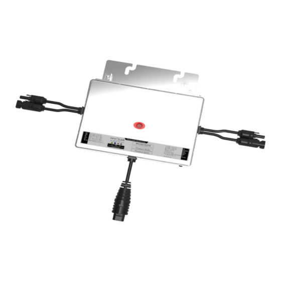
Page 25: Involar Mac500 Outside Dimension
. For details, refer to this manual, Section 3 Safety instruction and EC Directives, [Selection of fuse and cables]. 5.4 INVOLAR MAC500 outside Dimension Dimension as following Figure 5-1 shows: Figure 5-4 INVOLARMAC500 Micro-Inverter outside dimension Manual version 1.12 INVOLAR Corporation Ltd. -
Page 26: Detailed Installation Procedure
INVOLAR Corporation, Ltd. NOTE Allow enough space around the Micro-Inverter. Allow 350mm between two Micro-Inverters. The cables we recommend are as follow. AC cable Model DC cable AC Circuit breaker (Cu) mm2 MAC500 2x2.5+2,5 1,45 x Iz below Check that the operating time of the circuit breaker is below 5 seconds. - Page 27 Be aware that only competent personnel could connect INVOLAR Micro-Inverter to the electrical utility grid. DANGER DO NOT connect INVOLAR Micro-Inverter to the utility grid or energize the AC circuit(s) until the all installation procedures have been completed. WARNING ...
- Page 28 Figure 5.5.1MAC500 Micro-Inverter detailed Installation diagram Each of the detailed installation steps is in the above Figure 5-3 shows: ① Attaching the INVOLAR Micro-Inverters to the racking ② Connecting the INVOLAR Micro-Inverter left side cables. ③ Connecting the INVOLAR Micro-Inverter right side cables.
- Page 29 INVOLAR Corporation, Ltd. Grounding 1. Nut and bolt to racking system. Consider using WEEB type clips for improved earth connection. 2. Earth grounding terminal. Connect suitably size grounding cable as per Countries current wiring regulations and legislation Grid connection 1. Wire fastening and split Screw connection: Tightening torque typically 0.8Nm-1.0Nm...
- Page 30 INVOLAR Corporation, Ltd. 2. Connector fastening and split Tightening torque: Click! 4+1 Nm Click! 3. Connector Locking and split Manual version 1.12 INVOLAR Corporation Ltd. Mar. 2016...
-
Page 31: Function Instructions
Disable mode. The INVOLAR Micro-Inverter system keeps detecting the disable information. The INVOLAR Micro-Inverter is in disable mode until fault release. If the inoperative Micro-Inverter has been repaired and match to the electrical utility grid, the whole INVOLAR Micro-Inverter system would enter operation mode after 20 seconds to 5 minutes. -
Page 32: Gridconnection
Only to be carried out by qualified competentpersonnel. Start inverter after checking all below steps: WARNING Connect the INVOLAR Micro-Inverter to the electrical utility grid only after receiving prior approval from the utility company. WARNING Only competent qualified personnel shouldconnect INVOLAR Micro-Inverter to the electrical utility grid. -
Page 33: Start-Up Checks
INVOLAR Corporation, Ltd. Check screw connections on the inverter for tightness. The ambient operating conditions are allowed. (See Technical parameter); The unit is fixed properly on a non-flammable wall. (See Mechanical installation.) The cooling air will flow freely. The unit is fixed tightly and support is enough. -
Page 34: Disconnecting A Micro-Inverter From The Pv Module
INVOLAR Corporation, Ltd. 7 Disconnecting a Micro-Inverter from the PV Module To ensure safe disconnection of the micro-inverter from the PV array, it must NOT be carried out under load conditions. Ensure the following disconnection steps are carried out in the order shown: 1. -
Page 35: Monitoring And Troubleshooting And Maintenance
No user-serviceable parts inside.Servicing should be carried out by a competent person who has adequate technical knowledge of the product.Never operate this product and change any part of inverter yourself. For servicing you should contact INVOLAR Corporation direct or an authorized distributor. Safety checks... -
Page 36: Overview
The application of power line communication technology in INVOLAR MAC500 Micro-Inverter enables the users to monitor and maintain the whole PV system through the internet. By visiting INVOLAR’s website and entering the SEDAS portal(Solar Energy Data Acquisition System) customers can track real time statistics information of the energy harvest. - Page 37 INVOLAR Corporation, Ltd. Reporting Fields Explain Unit Grid Voltage Grid Voltage Grid Current Export DC Grid Frequency Grid Frequency DC input voltage DC input voltage Input DC Power Output Power Temperature Ambient temperature °C MAC500 Module Module Temperature °C Temperature...
- Page 38 INVOLAR Corporation, Ltd. NOTE Disabling the input of a single Micro-Inverter does not affect the operation of other INVOLAR Micro-Inverters in the system. WARNING Be aware that only qualified personnel should troubleshoot the PV array or the INVOLAR Micro-Inverter.
-
Page 39: Internet Web
9 Internet WEB Introduction Use The SEDAS(Solar Energy Data Acquisition System) developed by INVOLAR to real time track the statistics information of the energy harvest for all INVOLAR Micro-inverter system and monitor per-module’s performance which is integrated into the INVOLAR Micro-inverter system. -
Page 40: Involar Mac500 Micro-Inverter Technical Data
INVOLAR Corporation, Ltd. 10 INVOLAR MAC500 Micro-Inverter Technical Data Technical Specifications Model MAC500 PV Input Quantities Recommended PV Module 200W—300W *2 Rated DCVoltage (VMAX PV) 50V D.C. PV input Operating Voltage Range 24-40V Maximum Operating PV Input 10×2A Current Absolute Maximum Total PV Array Short Circuit Current (ISC PV) Max. - Page 41 INVOLAR Corporation, Ltd. Ingress Class NEMA6 Pollution degree 3, not intended for heavy pollution of the air by dust, smoke, Pollution degree corrective or radioactive particles, vapors or salt Protection against electric Class I shock An internal isolation transformer is...
-
Page 42: Appendix
INVOLAR products. During the warranty period, if any defect in workmanship and materials of the INVOLAR micro-inverters is detected, customers are entitled to ask for replacement or repairing from INVOLAR with no extra cost. -
Page 43: Involar Mac500 Micro-Inverter System Wiring Diagram
INVOLAR Corporation, Ltd. 12. INVOLAR MAC500 Micro-Inverter System Wiring Diagram Diagram 12.1 220/230/240V Connection Arrangement Manual version 1.12 INVOLAR Corporation Ltd. Mar. 2016...
Need help?
Do you have a question about the MAC500 Series and is the answer not in the manual?
Questions and answers