
Related Manuals for Allmand Maxi-Air MA375-DP T4F


Summary of Contents for Allmand Maxi-Air MA375-DP T4F
- Page 1 ™ Operator’s Manual Maxi-Air Towable Compressor Models MA375-DP T4F, MA400 T4F Copyright © 2019 Allmand Bros., Inc. 116028 Holdrege, NE, USA. All rights reserved. Revision B...
- Page 2 Customer Service by phone at (800) 562-1373, or on the Internet at allmand.com. Knowing the model number of your Allmand towable compressor will make it easy to order maintenance or repair parts either online or from your local dealer. The model number is generally a number stamped into metal or on a sticker directly on your product.
-
Page 3: Table Of Contents
Table of Contents Operator Safety..... . . 4 Features and Controls ....11 Set-Up and Installation . -
Page 4: Operator Safety
If in an enclosed area, vent the exhaust system to the outside. Do not modify or tamper with the exhaust system. Do not idle the engine except as necessary For more information, go to www.P65warnings.ca.gov/diesel ALLMAND.COM... - Page 5 Operator Safety Please indicate the MODEL / SER.No. on the plate of the machine when making inquiries. A plate stamped with the model and serial number is attached to the side of the machine. Each illustrated figure (Fig.) has a number (for instance, A130375) at the right bottom.
- Page 6 Operator Safety Safety Warning Labels The following safety warning labels are attached to the machine. If damaged or missing, contact your dealer for replacements. ALLMAND.COM...
- Page 7 Operator Safety Operator Safety Location of safety warning labels Location of safety warning labels...
- Page 8 As compressed air contains toxic gas etc., compressed air TR0092 should not be used to be blown or sprayed against food etc. Keep hands off from the rotating portion or belts while running. It could cause serious injuries if hands should be caught in. TR0304 ALLMAND.COM...
- Page 9 Operator Safety As part of pre-start safety checks, always confirm that there is no residual pressure in the tank by carefully opening the service valve, even if the pressure gauge on the screen indicates 0PSI. Note residual pressure in the separator receiver tank could ...
- Page 10 The engine of this machine and electrical parts many electronic devices have been installed. If you perform welding work, remove the connector of the electronic control equipment. Application of excessive current to electronic controls can cause equipment malfunction. ALLMAND.COM...
-
Page 11: Features And Controls
Features and Controls Features and Controls Internal Components F G H I J K A180429 MA400 T4F Description Function For releasing compressed air to the atmosphere when the pressure rises higher Safety valve than the rated pressure in the system. Air filter (For compressor air-end) Filtering device for filtering dust floating in intake air. - Page 12 For draining engine oil. Oil cooler drain valve For draining compressor oil from oil cooler and oil line. Radiator drain valve For draining engine coolant. DPF (Diesel Particulate Filter) Apparatus for removing harmful components contained in the exhaust gas. ALLMAND.COM...
- Page 13 Features and Controls D E F G H I O N M A180431 MA375-DP T4F Description Function SCR (Selective Catalytic Reduction) Selective reduction-type catalyst that uses DEF as a reducing agent Radiator For cooling the coolant for engine in the system Engine For driving the compressor air-end in the system Solenoid valve for unloader spring...
- Page 14 For separating water from compressed air cooled through after cooler After cooler For cooling compressed air Drain port of air pipe For draining condensate from drain separator For preventing freezing of water separated through drain separator when Drain warming valve exhausting it ALLMAND.COM...
-
Page 15: Set-Up And Installation
Set-Up and Installation Set-Up and Installation Transportation When loading and unloading the machine, make sure to use the lifting bail provided on the center of the machine top. Lifting 1. Before lifting the machine, make sure to check the lifting bail [A] for any cracks or loosened bolts. - Page 16 coupling or uncoupling. Make sure to drive the towing vehicle safely. Avoid dangerous situations or conditions on the road. Failure to obey the above instructions could result in death or serious injury, or serious equipment damage. ALLMAND.COM...
- Page 17 The machine must be parked perpendicular (on a right angle) to a slope. Set-Up and Installation The machine must not be parked on a slope more than 15° The machine should be operated in the following conditions: Ambient temperature-------------- -5°F to 104°F (-15℃...
- Page 18 安全护拦 Make sure to place a safety fence around the machine, to prevent unauthorized access to the machine. A120199 Service valve Bore of service valve: 20A(R3/4B)×2 Bore of service valve: 50A(Rc2B)×1 [Taper male screw] [Taper female screw] A160694 ALLMAND.COM...
- Page 19 Set-Up and Installation Warnings of hose attachment and removal Piping or air hoses connected to the service valves of this machine must meet or exceed the discharge pressure of the machine. Connect piping or air hoses to the service ...
-
Page 20: Operation
[START] button (MA375-DP T4F only) Switch to change high pressure Start operation by holding Switch to start and stop mode and low pressure mode. the button for 1 second. the unit. Touch Screen Display operation conditions and set each parameter. ALLMAND.COM... - Page 21 Operation Lubricating oil・Coolant・Fuel・DEF Engine oil Use recommended engine oil listed below. Be sure to use CJ class or higher engine oil or superior class. (Using engine oil with poor quality may shorten the life of the engine). Classification API service classification CJ-4 class or higher Viscosity SAE10W-30 Viscosity of engine oil greatly affects starting, performance, and oil consumption of...
- Page 22 Diesel fuel is required to meet the following conditions. Free from even minute dust particles. High optimum viscosity. High cetane number.(45 or more) High fluidity even at low temperature. Low carbon residue content. ALLMAND.COM...
- Page 23 Operation Operation DEF (AdBlue or equivalent) is transparent, colorless, and non-hazardous. In some circumstances, DEF will DEF (AdBlue or equivalent) is transparent, colorless, and non-hazardous. In some circumstances, DEF will put off odor, but this is normal and not indicative of any problems. put off odor, but this is normal and not indicative of any problems.
- Page 24 changed according to the periodic inspection list, change the oil. (See “Change Engine Oil” in Maintenance) When adding oil, do not overfill. Oil level gauge When oil level is within this zone, it is normal. HIGH A150804 ALLMAND.COM...
- Page 25 Operation Check coolant level Check the coolant level in the reserve tank. If it is lower than the limit, open the cap and replenish the coolant. (Level must be kept above LOW mark.) If it is lower than the limit or empty, open the cap and ...
- Page 26 Note residual pressure in the receiver tank could force both extremely hot compressed air and oil to jet out and you may be scalded or seriously injured. H990432 ALLMAND.COM...
- Page 27 Operation Check fuel Before starting operation, make sure to check the level of residual fuel so that fuel shortage during operation can be avoided. Drain condensate accumulated at the bottom of fuel tank whenever necessary. Refilling fuel tank should be done in an outdoor well-ventilated place. ...
- Page 28 Refill DEF to restore. Note: When refilling diesel fuel, refill DEF as well. DEF TANK LEVEL A180471 DEF Tank level display State DEF Level Over 15% Below 15% 5% 0% Description Icon (DEF Level) PUSH PUSH PUSH Indicator Engine Stop ALLMAND.COM...
- Page 29 Operation Check sedimenter for condensate When the red float [B] under the element [A] in the fuel filter is raised to the upper level, drain the condensate. 1. Turn the fuel selector valve [C] to the “OFF” position. 2. Loosen the drain valve [D] to drain out condensed water inside.
- Page 30 Pull the handle forward to open the door. Be sure to close the door tightly so that its latch is firmly caught. Keep the door closed and locked while running the unit. If the door has to be opened, keep hands away from rotating parts or hot components. D003 3-11 ALLMAND.COM...
- Page 31 Operation Operating Procedure For proper cooling and airflow, make sure that all enclosure doors are closed before starting. Procedure to start the unit Start-up procedure. During the warm-up operation, examine equipment for any looseness, leakage of water, oil, fuel, and other irregularities.
- Page 32 Be sure to let unit warm-up after starting for smooth operation of the engine and the compressor. Do not operate the engine at full load immediately after it starts up. This will shorten the equipment life. 3-13 ALLMAND.COM...
- Page 33 Operation How to select operating pressure [MA375-DP T4F] Set the PRESSURE SELECT switch [A] to the [LOW] position for 100PSI and the [HIGH] position for 150PSI. Note: You can alternate the usage pressure during operation. A180427 3-14...
- Page 34 Air-boosting mode ON When using air-boosting mode, air delivery will be increased by higher engine speed when the pressure is low. The air-boosting mode is on when the unit is shipped from factory. Air-boosting mode O FF A180483 3-15 ALLMAND.COM...
- Page 35 Operation Operating procedures when engine fails to start up on first attempt If the engine fails to start after following steps 1 through 4, set the CONTROL POWER switch to the position and wait 1 minute before attempting the steps again. If the repeated procedure does not allow the engine to run, the following causes are suspected.
- Page 36 Make sure that discharge pressure always reads at least 58PSI during operation. If you keep operating with less than 58PSI, it will causes less separation of lubricating oil at oil separator, or baking caused by overheat of compressor body. 3-17 ALLMAND.COM...
- Page 37 Operation Stopping 1. Close fully service valve. 2. Set the CONTROL POWER switch [A] to position. 3. The engine will stop automatically after a 180 second cool down. 4. After stopping the engine, close and lock the front panel. Store the key in a safe place. Unless all the service valves are fully closed upon stopping operation, the compressed air will be sent in ...
- Page 38 If cease the operation and storage the machine under use environment in winter season, be sure to open the service valve 2 to 3 times in order to remove water droplet in air piping such as after-cooler before stoppage of engine. 3-19 ALLMAND.COM...
- Page 39 Operation Selection of service air Switch the 3-way switching valve and you can use low or normal temperature air to meet your use. After cooler 3 way switching From pressure valve control valve Drain separator View from separator maintenance cover A150855 Service air Low temperature air...
- Page 40 Operation SETTING screen <HOME SCREEN> Operating condition, running parameters, and various other settings and be can be read and changed here. 3-21 ALLMAND.COM...
- Page 41 Operation SYSTEM DIAGRAM <MAIN SCREEN> 1. Press “HOME” on “MAIN” screen. 2. Select “SYSTEM DIAGRAM” 3. Current operating parameters are displayed. <HOME SCREEN> <SYSTEM DIAGRAM 1 (ENGINE)> <SYSTEM DIAGRAM 2 (COMPRESSOR)> 3-22...
- Page 42 Touch any of the settings and a numerical keypad will be displayed. Input the values required within range. <HOME SCREEN> <SETTING SCREEN> <SETTING> COOLING OPERATION TIME 180sec STARTING OPERATION TIME 120sec STARTING OPERATION DIS.TEMP. 140°F 3-23 ALLMAND.COM...
- Page 43 Operation MAINTENANCE The Maintenance alarm schedule for major items can be set at the user's discretion. <MAIN SCREEN> 1. Select “MAINTENANCE.” 2. “MAINTENANCE” screen is displayed. 3. Press “NEXT” to show engine items. 4. Touching any value will display a number pad. 5.
- Page 44 (Sampling interval is every 2 seconds, log time is up to 40 minutes.) Press “NEXT” to show graphs of each items. <MAIN SCREEN> <HOME SCREEN> <TREND GRAPH -2> <TREND GRAPH -1> <TREND GRAPH -3> <TREND GRAPH -4> <TREND GRAPH -5> 3-25 ALLMAND.COM...
- Page 45 Operation [Scroll graph] To scroll the graph, press the stop key on this screen to stop live updates. After pressing “STOP,” press to scroll graph. Press “UPDATE” to resume live updates to the graph. INITIAL SETTING The “INITIAL SETTING” section on the “HOME” screen is to restore the unit to factory settings. It is not ...
- Page 46 DPF if performed cold. If the DPF indicator is ON, take immediate action to perform the manual regeneration. Failure to do so could result in damage to the DPF or a fire in the exhaust system. 3-27 ALLMAND.COM...
- Page 47 Operation Emergency Stop Emergency stopping procedures If it is necessary to stop the machine for an emergency, press the Emergency Stop button which is set up under part of the operation panel. When doing shut down by emergency stop button, the machine will be stopped immediately.
-
Page 48: Troubleshooting
After clearing the cause of the error, press and hold the “RESET” button to clear the alert. <FAILURE engine> [ENGINE button blinking] Press “engine” to display diagnostic code(s). If necessary, contact your dealer for diagnosis and repair. ALLMAND.COM... - Page 49 Troubleshooting Indicator lamp and Warning / Emergency display [Indicator lamp] Turn the CONTROL POWER switch to position. Then the lamp goes on. Item Contents Measures Monitor When the unit is switched on, the preheat Glow indicator will be displayed briefly during ―...
- Page 50 ENGINE SPEED DOWN down. [Operation speed: less than 900min DISCHARGE Displayed when the air temperature sensor at the TEMP.SENSOR outlet port of compressor air end is disconnected. SEPARATOR Displayed when the separator outlet air TEMP.SENSOR temperature sensor is disconnected. DISCONNECTION ALLMAND.COM...
- Page 51 Troubleshooting SCR inducement If an SCR system error occurs, the SCR malfunction indicator [A] will blink. Check for the cause of the error and take appropriate action. If no action taken, after 3 hours 15 minutes the engine will begin shutting down.
- Page 52 (1)Air in fuel line Bleed air from fuel line is abnormal, and engine stops. (2)Engine air filter clogged Clean or change element Refer to the engine operator’s manual for engine issues. For all other issues, contact your dealer. ALLMAND.COM...
-
Page 53: Maintenance
Maintenance Maintenance Important Maintenance Items The following table shows the inspection and maintenance intervals under normal operating conditions. When operated under harsh environmental conditions, inspection and maintenance must be performed more often. General Maintenance Safety Wear protective gear, such as a helmet, safety glasses, earplugs, safety shoes, ... - Page 54 Be sure to carry out the following cleaning and inspection of the separator receiver tank at least once every year. Check for: Any damage found on the tank. • Any excessive wear found in the fastening bolts on the cover. • Any damage found to pipes and valves etc. • ALLMAND.COM...
- Page 55 Maintenance Maintenance Chart (Unit:Hour) Maintenance Daily 1,000 2,000 3,000 6,000 12,000 Check compressor oil level. ○ Drain separator receiver tank. ○ Check for looseness in pipe connecting part, and wear and ○ tear of pipe. Check oil, water, fuel and air leak. ○...
- Page 56 Note: Indicated replacement periods are rough estimates. Under harsh operating conditions, inspection/maintenance should be done more often. Maintenance 1,500 3,000 Remarks Change of breather filter element ○ Change DEF pump filter ● See engine manual for more details. Check DEF hoses ● See engine manual for more details. ALLMAND.COM...
- Page 57 Maintenance Replacement Parts Part number changes upon modification. For replacement of parts, make sure that the part number is correct or applicable. Part Number Part Name Quantity MA400 T4F MA375-DP T4F Engine oil filter element KUBOTA 1C020-32434 ← Air filter element for Element [C] 32143 12500 ←...
- Page 58 Engine oil is very hot and highly pressurized during or just after operation. Hot oil could blow out of the tank and can cause scalding. Never supply more engine oil than the proper level. Too much oil could result in engine damage. H990432 ALLMAND.COM...
- Page 59 Maintenance Change engine oil filter element At 50 hours for the first change and at every 500 hours thereafter 1. Remove the oil filter element [A], using a filter wrench. 2. Screw in the new oil filter element [A] with the gasket [B] coated slightly with oil.
- Page 60 Use only a 12V battery charger designed for the type of battery being charged. Remove the battery from the machine before charging. Do not charge two batteries at the same time. Be sure not to connect (+) and (–) terminals backwards. ALLMAND.COM...
- Page 61 Maintenance [How to use booster cables] Connect to the engine block of the machine 1. Stop the engine. 2. Connect one end of the (+) booster cable to the (+) terminal of the machine battery. 3. Connect the other end of the (+) booster cable to the (+) terminal of the external battery.
- Page 62 If compressor oil brands are mixed, the compressor air-end must be cleaned. Contact your dealer. Follow the designated regulations to dispose of compressor oil. 5-10 ALLMAND.COM...
- Page 63 Maintenance Change compressor oil filter element At 300 hours for the first change and every 500 hours thereafter Be sure to use genuine filter element. 1. Remove the oil filter element [A], using a filter wrench. 2. Screw in the new oil filter element [A] with the gasket [B] coated slightly with oil.
- Page 64 4. Bleed the air from the fuel. (See “Air Bleeding in Fuel Line.”) H000049 5. After installing the fuel filter, be sure to check for leakage during operation. For additional information, refer to the engine operator’s manual. 5-12 ALLMAND.COM...
- Page 65 Maintenance Clean element in sedimenter Every 500 hours 1. Turn the fuel selector valve to the position. 2. Loosen the drain valve and drain out condensed water inside. 3. Turn the cup to the left and remove it. Wipe out the inside of the cup.
- Page 66 Inspect and clean periodically. Change breather filter element Every 1,500 hours 1. Remove cap [A] of breather filter, and remove element [B]. 2. Install a new element [B] and firmly install the cap [A]. (For part number, See “Replacement Parts.”) A180188 5-14 ALLMAND.COM...
- Page 67 Maintenance Change coolant 1,000 hours or every 2 years Before changing coolant, stop the machine and allow the coolant to cool. 1. Loosen the radiator cap slowly to relieve pressure. 2. Remove the radiator cap [A]. Then remove the drain plug [B] and open the drain valve [C] slowly. 3.
- Page 68 Performance check of pressure control valve Every 6,000 hours Make sure that the pressure gauge indicates between 51 to 73 PSI when opening the service valve during operation. If the pressure is higher or lower than indicated above, contact your dealer. 5-16 ALLMAND.COM...
-
Page 69: Storage And Disposal
Storage and Disposal Storage and Disposal Preparation for Long-term Storage If the machine will not be used for more than six (6) months: 1. If possible, store the machine in a garage, shed, or other clean, dry place. Avoid storing the machine outside, even under a cover, as rust or corrosion may result. -
Page 70: Specifications
Lubricating oil capacity Coolant capacity 15.6 (including radiator) Battery Equivalent to 130F51×1 (12 V) Fuel tank capacity DEF tank capacity Overall length 2,630 (only for bonnet) Overall width 1,455 Overall height 1,210 Net dry mass 1,695 1,725 Operating mass 1,920 1,950 ALLMAND.COM... - Page 71 Specifications MA375-DP T4F Model MA375-DP T4F (After-cooler model) Type Single-stage oil cooled, screw type compressor 300/375 Free air delivery /min) (9.3)/(10.6) 150/100 Working pressure (MPa) (1.03)/(0.69) Engine speed(full load) 2,400/2,700 Engine speed(unload) 1,300 Lubricating system Forced Lubrication by compressed pressure Driving system Direct driving with rubber coupling Receiver tank capacity...
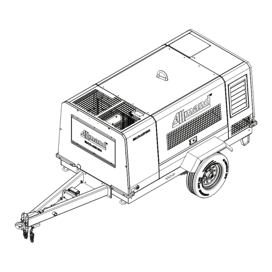
- Page 72 Specifications Outline drawing MA400 T4F MA375-DP T4F ALLMAND.COM...
- Page 73 Specifications MA400 T4F (After-cooler model) MA375-DP T4F (After-cooler model)
- Page 74 Specifications Piping Diagram Compression air・Compressor oil MA400 T4F ALLMAND.COM...
- Page 75 Specifications MA375-DP T4F...
- Page 76 Specifications MA400 T4F (After-cooler model) ALLMAND.COM...
- Page 77 Specifications MA375-DP T4F (After-cooler model)
- Page 78 Specifications Fuel Piping A180470E ALLMAND.COM...
- Page 79 Wiring Diagram...
- Page 80 ALLMAND.COM...
-
Page 82: Noise Emission
The Manufacturer reserves the right to make changes or add improvements without notice and without incurring any obligation to make such changes or add such improvements to products sold previously. The Purchaser is urged to include the above provisions in any agreement for any resale of this compressor. ALLMAND.COM... - Page 83 Noise Emission Control Maintenance Log COMPRESSOR MODEL __________________________ SERIAL NO. ___________________________________ USER UNIT NO. ________________________________ UNIT IDENTIFICATION DEALER OR DISTRIBUTOR FROM WHOM PURCHASED: Engine Make & Model: ________________ __________________________________ Serial No.: _________________________ __________________________________ Purchaser or Owner: _________________ __________________________________ Address: __________________________ Date Purchased: ____________________ The Noise Control Act of 1972 (86 Stat.
- Page 84 Equipment emission increase. and Engine Manufacturer’s Operator and Maintenance Manuals. E. Enclosure Panels Enclosure panels should also be inspected at 100 hour operational intervals. All panels that are warped, punctured, torn, or otherwise ALLMAND.COM...
- Page 85 Maintenance Record For Noise Emission Control Item Hourmeter Maint / Inspect Location Work Done Description Of Work Reading Date City / State By (Name)
-
Page 86: Addendum A - Unit Options
The green light (B) indicates full charge. (The battery charger can stay plugged in after the battery reaches full charge without damaging the battery.) 4. Unplug the battery charger before putting the unit into operation. ALLMAND.COM...
Need help?
Do you have a question about the Maxi-Air MA375-DP T4F and is the answer not in the manual?
Questions and answers