Table of Contents
Advertisement
Available languages
Available languages
Attention:
Do not remove the bindings holding the two extension arms until fully assembled. These are
spring-loaded and can cause serious injury if allowed to spring free.
Attention:
Read this instruction manual carefully and completely before mounting and
usage. Keep this manual for future reference.
Dear Customer:
Congratulations and thank you for buying an awning from us. To enjoy this product for a long time
and for your own and the safety of other people please obey the mounting instructions.
Before you start mounting and using the awning, please get familiar with this product. Make sure all parts listed up
in below packing lists are delivered and intact. If you find that there are parts missing or damaged please do not
install the awning but contact after service . Do not start the mounting if parts are missing.
Instructions for Installation
And Operation
1
Advertisement
Table of Contents

Subscribe to Our Youtube Channel
Related Manuals for Outsunny 840-149GN


Summary of Contents for Outsunny 840-149GN
- Page 1 Instructions for Installation And Operation Attention: Do not remove the bindings holding the two extension arms until fully assembled. These are spring-loaded and can cause serious injury if allowed to spring free. Attention: Read this instruction manual carefully and completely before mounting and usage.
- Page 2 List of the parts Item Name picture quantity Roller(left) Roller(right) Torsion bar with arm(left) Torsion bar with arm(right) Front bar(left) Front bar(right) Cloth guiding wire Item Name picture quantity Item Name picture quantity Gear box Hand crank with left roller support Roller support(right)
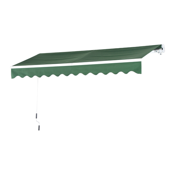
- Page 3 Description of Awning...
- Page 4 Important Safety Instructions Warning: For your own and the safety of other persons it is important to follow below instructions and obey warnings. Symbol explanation This warning triangle calls attention to hazards that it can lead to death or to severe injuries or which is important for the functioning of the awning.
- Page 5 In case of rain retract the awning if tilt angle is less than 14° . Nobody is allowed to climb onto the awning. Hanging anything on the awning is forbidden. Sheeting was used to protect the paint. This must be removed afterwards. When extended, various forces, including wind and rain, will affect an awning.
- Page 6 Step 2: Torsion bar assembly: Connect the front bar, (please keep the four face alignment, pay attention to the two arms need in the same direction, the rope of the arm cannot be solved.) As shown in the figure below: Step3: Front bar assembly Insert the right roller into the left roller directly as below picture.
- Page 7 Step 5: Arms with front bar assembly: Put front bar feet bolt through the hole of small arm, then position the front bar, As the dimensions shown in the figure below: Insert the right roller into the left roller directly as below picture. (please keep the roller alignment). Step 6: Locking the hexagon bolt After positioning, tighten the...
- Page 8 Step 7: Link the self-locking nut Link the self-locking nut into screw which at the bottom of the screw in front bar feet by a wrench, stop when the thread leakage 1 ~ 2 laps. As shown in the figure below: Step8: Left roller support with gear box assembly: Hammer the left roller support with gear box into the left end of torsion bar by wood hammer, then tighten the left hexagon bolt by 5mm...
- Page 9 Step 10: Roll in the fabric on the roller Roll in the fabric on the roller, pay attention to the fabric direction needed, as shown in the figure below: Please attention to downword the fabric edge B when assembling. Keep the same spacing X at both ends.Spread the fabric slowly in case of damage.
- Page 10 Step 12: Right roller support assembly: Set the Square tube plug into the right roller support, insert the shaft of roller into roll tube plug, meanwhile insert the torsion bar into the right roller supports with hitting. Then tighten the right hexagon bolt by 5mm Hexagon wrench.
- Page 11 Installation procedure: Step 1: Draw lines on the wall Choose the position,then draw up the position of bolt holt hole by pencil as blow picture,please make sure hole the of each group on the same horizontally or vertically.Attention:figure in “ L ”is product’s length ,the blow picture is mean the distance for brackets holes is L-14cm(For example: the product actual length of 2.95 m,the distance =2950mm-140mm=2810mm)...
- Page 12 Step 2. Installing the brackets Drill the hole according to the line which was draw up in step 1 by 14mm wall drill, please pay attention to the deep of hole that should not be less than 9cm. Making the expansion bolt through the bracket(keep the barbed side up), hitting the expansion bolt into the hole with tighten by wrench.
- Page 13 Step 5: Adjust the front bar Open the awning totally, and check whether it is horizontal and adjust the height of the front bar you need. Please noted the height between floor and front bar should be more than 2.5m. As shown in the figure: Note: The awning is already delivered with an optimally adjusted tilt angle.
- Page 14 Step 6: The right way of the awning using The awning can be operated normally when finish adjusting the horizontal of the front bar. Please use the awning in right way. As shown in the figure below: Maintenance Regular maintenance will not only help to keep a long durability but it is also important for your own and the safety of other people.
- Page 15 Anweisungen fü r Installation und Betrieb ACHTUNG: Entfernen Sie nicht die Spanngurte an den Gelenkarmen bevor Markise vollstä ndig zusammengesetzt ist. Die Arme stehen unter Spannung durch Federn und kö nnen ernsthafte Verletzungen verursachen sollten sie sich lö sen bevor die Markise vollstä ndig zusammengebaut und montiert wurde.
- Page 16 Liste der Einzelteile Artikelnummer Name Bild Anzahl Rolle (links) Links Rolle (rechts) Drehstab mit Links Gelenkarm (links) Drehstab mit Gelenkarm (rechts) Frontteil Links Frontteil Stofffü hrungsseil Handkurbel Getriebe mit Rolle links Rollenschutz (rechts) Vorderseite Haken Markisenstoff 2.95x2m,2.95x2.5m) Wandhalterung 3(3.95x2.5m) Spreizbolzen (2.95x2m,2.95x2.5m) (3.95x2.5m)
- Page 17 Sechskantschraube 2.95x2m,2.95x2.5m) 3(3.95x2.5m) Selbstsichernde Mutter Rollenverbindungs stü ck Abdeckung fü r Vorderseite Inbusschlü ssel Holzschraube (2.95x2m,2.95x2.5m) (3.95x2.5m) *Falls Sie das Produkt an einer Holzwand montieren nutzen Sie statt der Spreizbolzen (14) bitte die Holzschrauben (20).
- Page 18 BESCHREIBUNG DER MARKISE...
- Page 19 WICHTIGE SICHERHEITSHINWEISE Warnung: Fü r die Sicherheit von Ihnen und anderen Personen ist es wichtig, dass Sie die Anweisungen befolgen und die Warnungen berü cksichtigen. SYMBOLERKLÄRUNG Dieses Warndreieck weist auf Risiken bei dem Aufbau oder der Verwendung der Markise hin, die zu ernsthaften Verletzungen oder sogar dem Tod fü...
- Page 20 Die Markise sollte bei einem Neigungswinkel unter 14 Grad nicht im Regen aufgespannt sein. Das Kletter an oder auf die Markise ist strengstens Verboten! Es darf nichts an die Markise gehä ngt werden. Die Schutzfolie ist zum Schutz der Farbe gebraucht worden und muss im Nachhinein entfernt werden. Im ausgefahrenen Zustand haben verschiedene Krä...
- Page 21 Schritt 2: Anbringen der Drehstä be Verbinden Sie die Frontteile, (Achten Sie auf die Ausrichtung der Teile zueinander, beide Gelenkarme mü ssen in die gleiche Richtung zeigen) mit den Drehstä ben mit den Gelenkarmen und im Anschluss beide Teile miteinander. Links Links Links...
- Page 22 Schritt 5: Verbindung Forteile mit Drehstä ben Legen Sie das Frontteil an die Gelenkarme und die Haken durch das Loch in den kleinen Gelenkarmen. Siehe Abbildung Links Stecken Sie die rechte Rolle direkt in die Linke. Siehe Abbildung: (Bitte achten Sie auf die Einhaltung der Abstä...
- Page 23 Schritt 7: Anbringen der selbstsichernden Muttern Schrauben Sie die Muttern auf der Unterseite auf die Haken der Frontteile. Schrauben Sie bis sie einen Ruck spü ren und die Muttern fest sitzen. Siehe Abbildung: Schritt 8: Anbringen des Rollenschutz und des Getriebes links Hä...
- Page 24 Schritt 10: Aufrollen des Stoffs auf die Rolle Rollen Sie den Stoff auf die Rolle; Achten Sie dabei darauf mit der in der Abbildung angezeigte Richtung und Seite zu beginnen. Die Stoffseite B des Stoffes muss die Unterseite bilden. Achten Sie auß erdem darauf, auf beiden Seiten den gleichen Abstand zu den Enden der Markise einzuhalten.
- Page 25 Schritt 12: Anbringen rechter Rollenschutz Bringen Sie die Vierkantachse im rechten Rollenschutzteil an, stecken Sie die den Schaft der Rolle in die Öffnung und drü cken Sie das Schutzteil in den Dreharm. Schrauben Sie die Teile mit einer Sechskantschraube und dem Inbusschlü ssel fest. Siehe Abbildung: Schritt 13: Anbringen der letzten Teile Ziehen sie den Querbehang durch die Einkerbung auf der Vorderseite, achten Sie dabei auf die Richtung und stellen Sie sicher, dass die beiden Enden mit dem Stoff der Markise abschließ...
- Page 26 INSTALLATION: Schritt 1: Anzeichnen von Linien an der Wand Wä hlen Sie die gewü nschte Position und zeichnen Sie die Positionen der Bohrlö cher mit einem Bleistift wie auf der Abbildung an. Achten Sie darauf, dass sich die Lö cher horizontal bzw. vertikal auf einer Linie befinden.
- Page 27 Schritt 2: Anbringen der Wandhalterung Bohren Sie die Lö cher an den zuvor markierten Stellen mit einem 14mm Wandbohrer. Achten Sie darauf, dass die Lö cher nicht tiefer als 9 cm sein dü rfen. Stecken Sie die Spreizbolzen durch die Wandhalterung (Die eingekerbte Seite nach oben), drü cken sie die Wandhalterung in die Lö...
- Page 28 Schritt 5: Justieren der Vorderseite Öffnen Sie die Markise komplett und passen Sie die Hö he der Vorderseite/Frontteile nach Ihren Wü nschen an. Achten Sie darauf, die Mindesthö he von 2,50 m vom Boden bis zu den Frontteilen einzuhalten. Siehe Abbildung: Hö...
- Page 29 Schritt 6: Richtige Anwendung Nach dem Beendigen der Montage und Justierung kann die Markise normal genutzt werden. Bitte benutzen Sie die Markise nur wie vorgesehen. Siehe Abbildung: INSTANDHALTUNG UND PFLEGE Regelmä ß ige Pflege und Kontrolle der Markise gewä hrleistet nicht nur ihre Langlebigkeit sondern ist auch Ihrer eigene und die Sicherheit anderer Menschen.
- Page 30 Instructions pour l’installation et l’opération Attention: Ne retirez pas les fixations qui retiennent les deux bras d'extension avant de les avoir complé tement assemblé s. Ceux-ci sont à ressort et peuvent causer des blessures sé rieuses si laissé s libres. Attention: Lisez ce manuel d'instructions attentivement et complé...
- Page 31 Liste des composants Objet Photo Quantité Rouleau (gauche) Gauche Rouleau (droite) Barre de torsion Gauche avec bras (gauche) Barre de torsion avec bras (droit) Barre avant Gauche (gauche) Barre avant (droite) Fil de guidage de tissu Objet Photo Quantité Objet Photo Quantité...
- Page 32 Description de l’auvent...
- Page 33 Consignes de sé curité importantes Attention: Pour votre propre sé curité et celle des autres personnes, il est important de suivre les instructions ci-dessous et d'obé ir aux avertissements. Explication des symboles Ce triangle attire l'attention sur les dangers qui peuvent entraî ner la mort ou des blessures graves ou qui sont importants pour le fonctionnement de l'auvent.
- Page 34 En cas de pluie, ré tracter l'auvent si l'angle d'inclinaison est infé rieur à 14° . Personne n'est autorisé à monter sur l'auvent. Suspendre quoi que ce soit sur l'auvent est interdit. Les feuilles é taient utilisé es pour proté ger la peinture. Cela doit ê tre retiré aprè s. Une fois é...
- Page 35 Étape 2: Assemblage de la barre de torsion Connectez la barre avant, (s'il vous plaî t garder l'alignement à quatre faces, faites attention aux deux bras qui doivent ê tre dans la mê me direction, la corde du bras ne peut pas ê tre ré...
- Page 36 Étape 5: Bras avec assemblage de la barre avant: Placer les boulons de la barre avant dans le trou du petit bras, puis positionner la barre avant, comme indiqué dans la figure ci-dessous: Gauche Gauche Insé rez le rouleau droit dans le rouleau gauche directement comme ci-dessous. (s'il vous plaî t garder l'alignement des rouleaux).
- Page 37 Étape 7: Lier l'é crou autobloquant Relier l'é crou autobloquant dans la vis qui au fond de la vis dans les pieds de la barre avant par une clé , arrê ter lorsque la fuite de fil 1 ~ 2 tours. Comme le montre la figure ci-dessous: Étape 8: Support de rouleau gauche avec l'ensemble de boî...
- Page 38 Étape 10: Rouler dans le tissu sur le rouleau Rouler dans le tissu sur le rouleau, faire attention à la direction du tissu né cessaire, comme le montre la figure ci-dessous: S'il vous plaî t attention au le bord du tissu B lors de l'assemblage. Gardez le mê...
- Page 39 Étape 12: Assemblage du support du rouleau droit: Placer le bouchon du tube carré dans le support du rouleau droit, insé rer l'arbre du rouleau dans le bouchon du tube du rouleau, pendant ce temps insé rer la barre de torsion dans les supports du rouleau droit en frappant.
- Page 40 Procé dure d'installation: Étape 1: Dessinez des lignes sur le mur Choisissez la position puis dessinez la position du trou de boulon avec un crayon comme dans l’image, s'il vous plaît assurez-vous que le trou de chaque groupe est sur la mê me position horizontale ou verticale.
- Page 41 Étape 2. Installation des supports Percez le trou selon la ligne qui a é té tracé e à l'é tape 1 par une perceuse murale de 14mm, faites attention à la profondeur du trou qui ne doit pas ê tre infé rieure à 9cm. Passer le boulon d'expansion à...
- Page 42 Étape 5: Ajustez la barre avant Ouvrez complé tement l'auvent et vé rifiez s'il est horizontal et ajustez la hauteur de la barre avant autant que vous avez besoin. S'il vous plaî t noter la hauteur entre le sol et la barre avant devrait ê...
- Page 43 Étape 6: La bonne façon d’utiliser l'auvent L'auvent peut ê tre utilisé normalement lorsque vous avez fini de ré gler l'horizontale de la barre avant. Veuillez utiliser l'auvent de la bonne maniè re. Comme le montre la figure ci- dessous: Entretien Un entretien ré...
- Page 44 Istruzioni per l’installazione e l’uso Attenzione: Non rimuovere i legami che detengono i due bracci estensibili fino a che non sia completamente assemblato. Questi sono caricati a molla e possono causare gravi lesioni se permesso di liberarsi della molla. Attenzione: Leggere attentamente e completamente questo manuale di istruzioni prima dell'installazione e dell'utilizzo.
- Page 45 Liste des composants Oggetto Nome Foto Quantità Rullo (a sinistra) Sinistro Rullo (a destra) Barra di torsione Sinistra con braccio (a sinistra) Barra di torsione con braccio (a destra) Barra anteriore Sinistra (a sinistra) Barra anteriore (a destra) Filo di guida del panno Oggetto Nome...
- Page 46 Descrizione della tenda da sole...
- Page 47 Importanti istruzioni di sicurezza Attenzione: Per il proprio e per la sicurezza di altre persone, è importante seguire le istruzioni riportate di seguito e osservare le avvertenze. Spiegazione dei simboli Questo triangolo di avvertimento richiama l'attenzione sui rischi che può portare alla morte o a gravi lesioni o che è...
- Page 48 In caso di pioggia ritirare la tenda se l'angolo di inclinazione è inferiore a 14 ° . Nessuno è autorizzato a salire sul tendalino. Mettere qualcosa sulla tenda è vietato. Le lastre sono state utilizzate per proteggere la vernice. Questo deve essere rimosso in seguito.
- Page 49 Fase 2: Assemblaggio della barra di torsione: Collegare la barra anteriore (si prega di mantenere l'allineamento a quattro facce, prestare attenzione alle due bracci che devono essere nella stessa direzione, la corda del braccio non può essere risolta.) Come mostrato nella figura seguente: Sinistra Sinistra Sinistra...
- Page 50 Fase 5: Armi con gruppo anteriore: Mettere le punte del piede anteriore del foro attraverso il foro del braccio piccolo, quindi posizionare la barra anteriore, come le dimensioni mostrate nella figura seguente: Sinistra Sinistra Inserire direttamente il rullo destro nel rullo sinistro come illustrato sotto. (si prega di mantenere l'allineamento del rullo).
- Page 51 Fase 7: Collegare il dado autobloccante Collegare il dado autobloccante nella vite che nella parte inferiore della vite dei piedini anteriori della chiave da una chiave, arrestarsi quando il filo perdere 1 ~ 2 giri. Come mostrato nella figura seguente: Fase 8: Supporto rullo sinistro con gruppo scatola ingranaggi: Martello il supporto del rullo sinistro con la scatola ingranaggi nell'estremità...
- Page 52 Fase 10: ruotare nel tessuto sul rullo Ruotare nel tessuto sul rullo, prestare attenzione alla direzione del tessuto necessaria, come mostrato nella figura seguente: Si prega di prestare attenzione al segno del bordo del tessuto B durante l'assemblaggio. Tenere la stessa distanza X in entrambe le estremità . Spargere lentamente il tessuto in caso di danni.
- Page 53 Fase 12: Assemblaggio destra del supporto del rullo: Posizionare il tappo del tubo quadrato nel supporto destro del rullo, inserire l'albero del rullo nella spina del tubo di rotolamento, nel frattempo inserire la barra di torsione nei supporti rullo destro col colpo. Quindi serrare il bullone esagonale destro con la chiave esagonale da 5mm.
- Page 54 Procedura di installazione: Fase 1: Disegnare le linee sulla parete Scegli la posizione quindi tracciate la posizione del foro del bullone con la matita come immagine soffiata, assicurati che il foro di ciascun gruppo sia nella stessa posizione orizzontale o verticale. Attenzione, la figura in "L"...
- Page 55 Fase 2. Installazione delle staffe Forare il secondo foro secondo la linea che è stato redatta nella fase 1 di 14 mm trapano a parete, si prega di prestare attenzione alla profondità di foro che non deve essere inferiore a 9 cm.
- Page 56 Fase 5: Regolare la barra anteriore Aprire totalmente la tenda e verificare se è orizzontale e regolare l'altezza della barra anteriore necessaria. Si prega di notare che l'altezza tra il pavimento e la barra anteriore dovrebbe essere superiore a 2,5 m. Come mostrato in figura: lunghezza totale Altezza...
- Page 57 Fase 6: Il modo giusto di utilizzazione della tenda La tenda può essere azionata normalmente quando finisce di regolare l'orizzontale della barra anteriore. Utilizzate la tenda in modo corretto. Come mostrato nella figura seguente: Manutenzione La manutenzione regolare non solo contribuisce a mantenere una lunga durata, ma è anche importante per il proprio e per la sicurezza di altre persone.
Need help?
Do you have a question about the 840-149GN and is the answer not in the manual?
Questions and answers
Approximately how long does it take to install the canopy
How long does the canopy take to install