Advertisement
Available languages
Available languages
Quick Links
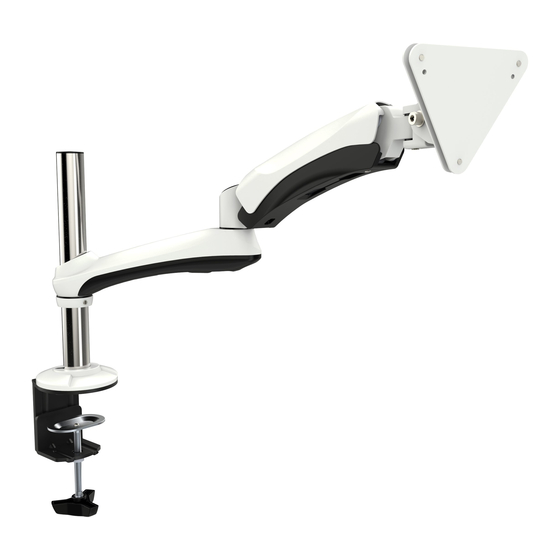
Tischhalterung höhenverstellbar
für iMac® 24" und iMac® 27"
MONTAGEANLEITUNG
v.16.8
ACHTUNG: NIEMALS DAS MAXIMAL
ZULÄSSIGE BELASTUNGSGEWICHT
ÜBERSCHREITEN. MISSACHTUNG
KANN ZU SACHSCHÄDEN ODER
SCHWEREN VERLETZUNGEN FÜHREN!
11kg
TS0511
(24lbs)
MAX
Deutsch
English
Advertisement

Related Manuals for ricoo TS0511


Summary of Contents for ricoo TS0511
- Page 1 Tischhalterung höhenverstellbar für iMac® 24" und iMac® 27" MONTAGEANLEITUNG v.16.8 ACHTUNG: NIEMALS DAS MAXIMAL ZULÄSSIGE BELASTUNGSGEWICHT ÜBERSCHREITEN. MISSACHTUNG KANN ZU SACHSCHÄDEN ODER SCHWEREN VERLETZUNGEN FÜHREN! 11kg TS0511 (24lbs) Deutsch English...
- Page 2 ACHTUNG: Lesen Sie die gesamte Bedienungsanleitung durch, bevor Sie mit der Montage beginnen. WARNUNG • Beginnen Sie nicht mit der Montage, bis Sie alle Anweisungen und Warnungen, welche in dieser Montageanleitung vorhanden sind, durchgelesen und verstanden haben. Wenn Sie Fragen zu den Anweisungen oder Warnungen haben, kontaktieren Sie bitte Ihren Händler.
- Page 3 Lieferumfang WICHTIG: Stellen Sie vor der Montage sicher, dass alle Teile welche hier aufgeführt sind, bei der Lieferung dabei sind. Sollten Teile fehlen oder defekt sein, kontaktieren Sie Ihren Händler. B (x1) A (x1) C (x1) D (x1) E (x1) F (x3) G (x3) H (x3)
- Page 4 Schritt 1 1a. Montage an die Tischkante Das Aufkleben des Gummipads ist in der Regel nur bei den Tischen mit Glas-Tischplatten notwendig und dient dem Schutz der Glasoberfläche der Tischplatte. auflkeben aufkleben Beachten : min. Tischdicke = 10mm max. Tischdicke = 90mm Deutsch English...
- Page 5 1b. Montage im Tischloch Schritt 1b ø:10mm~70mm aufkleben Beachten : min. Tischdicke = 10mm max. Tischdicke = 90mm Deutsch English...
- Page 6 Schritt 2 Schritt 3 Deutsch English...
- Page 7 Schritt 4 Schritt 5 Deutsch English...
- Page 8 Schritt 6 (a). Gewichtsausgleich einstellen Schritt 1: Kontermutter entfernen Entfernen Sie die Kontermutter mit Hilfe eines Schraubenziehers. Deutsch English...
- Page 9 Schritt 6 (b). Gewichtsausgleich einstellen Schritt 2: Klemmschraube einstellen. Großer Kleiner Bildschirm Bildschirm ACHTUNG: Gewichtsausgleicheinstellung nur nach der Bildschirmmontage durchführen! In diesem Arbeitsschritt darf ausschließlich nur mit dem Inbusschlüssel gearbeitet werden! Bitte halten Sie das Gelenk während Sie die Gewichtsausgleicheinstellung durchführen. Verwenden Sie den passenden Inbusschlüssel.
- Page 10 Schritt 6 (c). Gewichtsausgleich einstellen Schritt 3: Kontermutter einsetzen Nach der Gewichtseinstellung, setzen Sie die Kontermutter wieder ein und ziehen diese bis zum Anschlag an. BITTE BEI DER SPÄTEREN DEMONTAGE DES BILDSCHIRMS DARAUF ACHTEN, DASS SICH DER HALTERARM BEI DER ABNAHME DES MONITORS OBEN BEFINDET! W A R N U N G ! Achtung: Der Arm kann aufgrund der Gasdruckfeder nach oben schnellen! Durch die Nicht-Beachtung des Hinweises kann es zu Verletzungen führen.
- Page 11 Schritt 7 Schritt 8 -90° +35° Deutsch English...
- Page 12 Schritt 9 +3° -3° 180° 180° 180° Wartung • Prüfen Sie in regelmäßigen Abständen (mindestens alle drei Monate), ob alle Schrauben an dem Produkt fest angezogen sind. • Bei Fragen kontaktieren Sie Ihren Händler. Fertig Deutsch English...
- Page 13 Interactive Counterbalance Desk Mount for iMac® 24" and iMac® 27" MONTAGEANLEITUNG v.16.8 CAUTION: DO NOT EXCEED RATED LISTED WEIGHT. SERIOUS INJURY OR PROPERTY DAMAGE MAY OCCUR! 11kg TS0511 (24lbs) English Deutsch...
- Page 14 NOTE: Read the entire instruction manual before you start installation and assembly. WARNING • Do not begin the installation until you have read and understood all the instructions and warnings contained in this installation sheet. If you have any questions regarding any of the instructions or warnings, please contact your local distributor.
-
Page 15: Component Checklist
Component Checklist IMPORTANT: Ensure that you have received all parts according to the component checklist prior to installation. If any parts are missing or faulty, telephone your local distributor for a replacement. B (x1) A (x1) C (x1) D (x1) E (x1) F (x3) G (x3) - Page 16 Step 1 1a. Edge Installation The adhesive bonding of the rubber pad is normally necessary only if it is a glas-topped table. It serves to protect the glas surface of the tabletop. stick on stick on Note: min. desktop thickness = 10mm max.
- Page 17 1b. Hole Installation ø:10mm~70mm stick on Note: min. desktop thickness = 10mm max. desktop thickness = 88mm English Deutsch...
- Page 18 Step 2 Step 3 English Deutsch...
- Page 19 Step 4 Step 5 English Deutsch...
- Page 20 Step 6 (a). Tension Adjustment Step 1: Locknut removing Remove the lock nut using a screwdriver. English Deutsch...
- Page 21 Step 6 (b). Tension Adjustment Step 2: Adjusting the clamping screw Small TV Big TV WARNING: Perform the tension-balance adjustment only after the screen assembly! This operation must be carried out only with the Allen key! Please keep the arm level during tension adjustment. Use a proper Allen key to slightly loosen or tighten the adjustment screw according to the display weight.
- Page 22 Step 6 (c). Tension Adjustment Step 3: Insert Locknut After the tension adjustment, set the lock nut again and tighten it until it stops. DURING THE LATER REMOVING OF THE DISPLAY MAKE SURE THE FRONT ARM IS ON TOP BEFORE TAKING OFF THE DISPLAY! W A R N I N G ! Attention: The arm can shoot up upwards because of the gas pressure spring! If you don't pay attention you can be injured.
- Page 23 Step 7 Step 8 -90° +35° English Deutsch...
- Page 24 Step 9 +3° -3° 180° 180° 180° Maintenance • Check that the bracket is secure and safe to use at regular intervals(at least every three months). • Please contact your distributor if you have any questions. Done English Deutsch...
Need help?
Do you have a question about the TS0511 and is the answer not in the manual?
Questions and answers