Advertisement
Available languages
Available languages
Quick Links
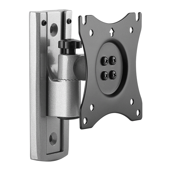
Vollbeweglich LED, LCD TV Wandhalterung
Bitte überprüfen Sie VOR der Montage den Lochabstand zwischen den VESA-Befestigungs-
!
löchern an Ihrem Bildschirm
Diese Wandhalterung unterstützt folgende Lochabstände:
Horizontal / Waagerecht
Vertikal / Senkrecht
S3111
VESA-Befestigungslöcher
Vertikal /
Senkrecht
Horizontal / Waagerecht
75x75
100x100
MONTAGEANLEITUNG
ACHTUNG: NIEMALS DAS MAXIMAL
ZULÄSSIGE BELASTUNGSGEWICHT
ÜBERSCHREITEN. MISSACHTUNG
KANN ZU SACHSCHÄDEN ODER
SCHWEREN VERLETZUNGEN FÜHREN!
Bildschirm Rückseite
75mm , 100mm
75mm , 100mm
Deutsch
v.16.8
15kg
(33lbs)
MAX
English
Advertisement

Related Manuals for ricoo S3111


Summary of Contents for ricoo S3111
- Page 1 Bitte überprüfen Sie VOR der Montage den Lochabstand zwischen den VESA-Befestigungs- löchern an Ihrem Bildschirm VESA-Befestigungslöcher Vertikal / Senkrecht Horizontal / Waagerecht Bildschirm Rückseite Diese Wandhalterung unterstützt folgende Lochabstände: Horizontal / Waagerecht 75mm , 100mm Vertikal / Senkrecht 75mm , 100mm S3111 75x75 15kg 100x100 (33lbs) Deutsch English...
- Page 2 ACHTUNG: Lesen Sie die gesamte Bedienungsanleitung durch, bevor Sie mit der Montage beginnen. WARNUNG • Beginnen Sie nicht mit der Montage, bis Sie alle Anweisungen und Warnungen, welche in dieser Montageanleitung vorhanden sind, durchgelesen und verstanden haben. Wenn Sie Fragen zu den Anweisungen oder Warnungen haben, kontaktieren Sie bitte Ihren Händler.
- Page 3 Lieferumfang WICHTIG: Stellen Sie vor der Montage sicher, dass alle Teile welche hier aufgeführt sind, bei der Lieferung dabei sind. Sollten Teile fehlen oder defekt sein, kontaktieren Sie Ihren Händler. D (x4) A (x1) B (x2) C (x1) 3mm (x1) 5mm (x1) Paket M M4x14 (x4)
- Page 4 Schritt 2 Holzbalkenwand 55mm Variante A (2.2") ohne hinterer Montageplatte ø 4.5mm (ø 3/16") √ Deutsch English...
- Page 5 Variante B mit hinterer Montageplatte Deutsch English...
- Page 6 Massivbetonwand 60mm Variante A (2.4") ohne integrierter Wasserwaage ø 10mm (ø 3/8") Achtung: Mitgelieferte Dübel sind nur für Massivbetonwände geeignet! √ Deutsch English...
- Page 7 Variante B ohne integrierter Wasserwaage Deutsch English...
- Page 8 Schritt 3 Schritt 4 Deutsch English...
- Page 9 Schritt 5 Schritt 6 90° -55° 35° Fertig Deutsch English...
- Page 10 Please check BEFORE installation distance between VESA mounting holes on your display! VESA-Mounting holes Vertical / Perpendicularly Horizintally Display back This wall mount supports the following distance between holes: Horizontally 75mm , 100mm 75mm , 100mm Vertical / Perpendicularly S3111 75x75 15kg 100x100 (33lbs) Deutsch English...
- Page 11 NOTE: Read the entire instruction manual before you start installation and assembly. WARNING • Do not begin the installation until you have read and understood all the instructions and warnings contained in this installation sheet. If you have any questions regarding any of the instructions or warn- ings, please contact your local distributor.
- Page 12 Component Checklist IMPORTANT: Ensure that you have received all parts according to the component checklist prior to installation. If any parts are missing or faulty, telephone your local distributor for a replacement. D (x4) A (x1) B (x2) C (x1) 3mm (x1) 5mm (x1) Paket M...
- Page 13 Step 2 Wood stud wall 55mm Variation A (2.2") without rear mounting plate ø 4.5mm (ø 3/16") √ English Deutsch...
- Page 14 Variation B with rear mounting plate English Deutsch...
- Page 15 Concrete wall 60mm Variation A (2.4") without integrated spirit level ø 10mm (ø 3/8") Warning: Supplied plastic anchors are only suitable for solid concrete walls! √ English Deutsch...
- Page 16 Variation B with integrated spirit level English Deutsch...
- Page 17 Step 3 Step 4 English Deutsch...
- Page 18 Step 5 Step 6 90° -55° 35° Done English Deutsch...
Need help?
Do you have a question about the S3111 and is the answer not in the manual?
Questions and answers