Table of Contents
Advertisement
Available languages
Available languages
Quick Links
Advertisement
Chapters
Table of Contents

Related Manuals for Rohde ELS-S Series


Summary of Contents for Rohde ELS-S Series
- Page 1 Aus Freude am Ergebnis Bedienungsanleitung ELS-S – Ergo Load System...
-
Page 2: Table Of Contents
Aus Freude am Ergebnis! INHALTSVERZEICHNIS Seite Vorwort Wichtige Sicherheitshinweise 2.1. Allgemeine Anmerkungen 2.2. Sicherheitshinweise 2.3. Technische Beschreibung 2.4. Sicherheits- und Arbeitsschutzkleidung 2.4. Sicherheitshinweise für den Einsatz Inbetriebnahme 3.1. Anlieferung 3.2. Betriebsumgebung / Aufstellort 3.3. Brennofen ELS-S aufstellen 3.4. Brennofen mit Werkstattboden verschrauben 3.5. -
Page 3: Vorwort
Aus Freude am Ergebnis! 1. VORWORT Herzlichen Glückwunsch, Sie haben sich für einen ROHDE – Ergo Load System kurz ELS Brennofen entschieden, einem Markenprodukt für höchste Ansprüche. Dieser ELS-S Brennofen ist das Ergebnis intensiver Weiterentwicklung der Baureihe ELS. Diese Bedienungsanleitung soll Ihnen das Kennenlernen Ihres ROHDE – ELS-S Brennofens vereinfachen. -
Page 4: Technische Beschreibung
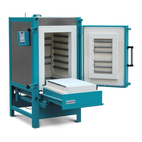
■ Ofenserie mit 5 Modellen von 200 bis 1000 Litern ■ Hinterlüftung der gesamten Gehäusekonstruktion ■ Heizwendeln 5-seitig auf Tragrohren montiert ■ Deckenkonstruktion "System ROHDE" (DGM) ■ 3-schichtiger, Energie-effizienter Isolationsaufbau ■ Standardmäßig 1 Zonen-Steuerung ■ Leistungsregelung über Halbleiterschalter, leise und verschleißfrei Maximaltemperatur: 1320°... -
Page 5: Sicherheits- Und Arbeitsschutzkleidung
2.4. Sicherheits- und Arbeitsschutzkleidung: Beim Öffnungs- bzw. Ausfahrvorgang des ELS-S Brennofens muss das Bedienpersonal ent- sprechende Arbeitsschutzkleidung tragen. Hohe, austretende Temperaturen können zu Verletzungen führen. Die Helmut Rohde GmbH übernimmt für Personen- und Sachschäden keine Haftung! 2.5. Sicherheitshinweise für den Einsatz Nur unter Einhaltung der folgenden Sicherheitshinweise kann ein gefahrloser Betrieb des ROHDE –... -
Page 6: Inbetriebnahme
3. INBETRIEBNAHME 3.1. Anlieferung In der Regel wird der ROHDE – ELS-S Brennofen mit Spedition geliefert. Die Sendung ist in jedem Fall bei der Anlieferung sofort auf Beschädigungen zu prüfen. Wird der Lieferschein ohne vorherige Warenprüfung unterzeichnet, gilt die Sendung als unbeschädigt und korrekt angeliefert. -
Page 7: Brennofen Els-S Aufstellen
Aus Freude am Ergebnis! 3.3. Brennofen ELS-S aufstellen Sollte der ELS-S Brennofen nicht bereits durch den ROHDE Liefer- und Aufstellservice aufge- stellt worden sein, ist es nun an der Zeit, den Brennofen aufzustellen. Zuerst muss der Brennofen vorsichtig von der Transportpalette gehoben werden. Mit Hilfe eines geeigneten Gabelstaplers können Sie den ELS-S –... -
Page 8: Brennofentüre Öffnen
Falsch gestapelte, umfallende Brennware kann zu Verletzungen führen und den Brennofen beschädigen. Das Bedienpersonal muss ausreichende Schutzkleidung tragen! Die Helmut Rohde GmbH übernimmt für Personen- und Sachschäden infolge unsachgemäßer Bedienung keine Haftung! Öffnen Sie durch Drehen der beiden Sterngriffschrauben (Bild) in Pfeilrichtung nach links. Öffnen Sie dann die Türe des Brennofens vollständig. -
Page 9: Els-S Boden Herausfahren
Aus Freude am Ergebnis! 3.6. ELS-S Boden herausfahren ACHTUNG: Den Wagen niemals verfahren, wenn die Türe nicht vollständig geöffnet ist! Dies kann zu Beschädigungen der Ofenanlage führen. ELS 200 und 330 S Bei eingefahrenem Wagen sorgt die Rollen- Benutzen Sie dazu (mit Pfeil markiert) lagerstütze dafür, dass die Wagenmesser Zugvorrichtung sauber in die Dichtung eingeführt werden. - Page 10 Aus Freude am Ergebnis! ELS 480 bis 1000 S Bei eingefahrenem Wagen sorgt der Damit der Ofenwagen herausgefahren Kniehebelspanner dafür, dass der Wagen werden kann, muss im ersten Schritt der bei geöffneter Türe im Brennofen gehalten Kniehebelspanner entspannt werden. wird. Benutzen Sie dazu (mit Pfeil markiert) die Zugvorrichtung auf der Vorderseite des Fahrbodens.
-
Page 11: Els-S Boden Beladen
Aus Freude am Ergebnis! 3.7. ELS-S Boden beladen Platzieren Sie die mitgelieferten Cordierit-Klötzchen im Dreieck auf der Bodenplatte des Wagens, legen Sie dann eine erste Besatzplatte (optionales Zubehör) mittig darauf. Besatzaufbau mit 3-Punkt Auflage Cordierit Klötzchen mit Grundplatte Zu empfehlen ist eine 3-Punkt-Auflage der Besatzplatten, wobei jeweils Stütze über Stütze stehen sollte, da ansonsten die Platten auf Biegung beansprucht werden, was immer wieder zu Verformungen oder Riss der Besatzplatten führt. - Page 12 Aus Freude am Ergebnis! ELS 480 bis 1000 S Soll der Wagen in den Ofen eingefahren werden, muss der Stift zur Wagenfixierung gelöst werden. Dann kann der Wagen eingefahren werden. Fahren Sie den Wagen vorsichtig in den Sichern Sie den eingefahrenen Wagen Brennraum.
-
Page 13: Brennofentüre Schließen
Sterngriffschrauben (Bild) in Pfeilrichtung nach rechts! 3.10. Zuluftschieber manuell Alle Modelle der Rohde – ELS-S Brennofen verfügen über einen Zuluftschieber Mit dem Schieber werden die Zuluftklappen bedient: Wird der Schieber vollständig herausgezogen, sind die Zuluftklappen vollständig geöffnet. Ist der Zuluftschieber in voller Länge eingeschoben so ist die Luftzuführung geschlossen. -
Page 14: Abluftklappen Manuell
Aus Freude am Ergebnis! 3.11. Abluftklappen manuell Alle Modelle der Rohde – ELS Serie verfügen über manuell einstellbare Abluftklappen auf der Decke des Ofens. Ist der Abluftschieber in voller Länge eingeschoben, ist die Abluftführung geschlossen. Wird der Schieber vollständig herausgezogen, ist die Abluftöffnung geöffnet. -
Page 15: Hinweise Stromanschluss
Aus Freude am Ergebnis! 3.13. Hinweise Stromanschluss Für den Betrieb Ihres Brennofens in Werkstätten, Laborräumen, etc. ist es unbedingt erforderlich, eine separate Stromzufuhr mit eigener Absicherung von einer Elektrofachkraft bereitstellen zu lassen. 3.14. RCD-Schutzschalter RCD-Schutzschalter mit 0,03 A Auslösestrom (z.B. für Feuchträume in Wohnungen) können zum vorzeitigen Auslösen (z.B. -
Page 16: Montage Der Regelanlage Auf Der Els - Reglerplatte
Aus Freude am Ergebnis! Stecken Sie bitte zuerst den schwarzen Regelungsstecker ein. Eventuell müssen Sie den Stecker etwas drehen, bis er einrastet. Dann den Verschraubungsring festdrehen und damit den Stecker sichern. Ist der Stecker nicht vollständig oder richtig eingeschraubt, lässt sich die Regelanlage nicht einschalten! Damit der ELS Brennofen endgültig in Betrieb genommen werden kann, muss dieser an das Stromnetz angeschlossen werden. -
Page 17: Ofen Einbrennen / Besatzmaterial Einbrennen
Aus Freude am Ergebnis! 3.18. Ofen einbrennen / Besatzmaterial einbrennen ACHTUNG: Entfernen Sie nun unbedingt die Styroporplatten, welche als Transportsicherung und Schutz der SIC – Bodenplatte dienen. Bevor der Ofen in den täglichen Gebrauch geht, sollte ein Trockenbrand gefahren werden. Das „Einbrennen“... -
Page 18: Bedienung Der Regelanlage
Aus Freude am Ergebnis! 4. ALLGEMEINE BEDIENHINWEISE 4.1. Bedienung der Regelanlage ACHTUNG: Bitte lesen Sie zunächst die entsprechende Betriebsanleitung für Ihre Regelanlage sorgfältig durch! 4.2. Richtiger Umgang beim Brand Keine brennbaren Gegenstände in unmittelbare Nähe legen. Der Brennofen darf nur in einer gut belüftbaren Werkstatt/ Raum aufgestellt und betrieben werden. Um einen zuverlässigen Betrieb des Brennofens zu gewährleisten, darf der Ofen nur bis zu einer Umgebungstemperatur von 40°C betrieben werden. -
Page 19: Wartung / Pflege Und Reinigung
Aus Freude am Ergebnis! 5. WARTUNG / PFLEGE / REINIGUNG ACHTUNG: Unter Spannung stehende Bauteile – Lebensgefahr! Der Brennofen muss vollständig stromlos geschalten werden! Erst nach Prüfung der Sicherheit darf das Wartungspersonal den Brennraum betreten und den Elektrokasten öffnen. 5.1. Wartung Wartungsarbeiten: ... -
Page 20: Isolierkordel Abdichten
Aus Freude am Ergebnis! 5.1.2 Isolierkordel abdichten TIPP: Es ist ratsam, die Isolierkordel in der Brennofen Türe von Zeit zu Zeit durch zusammendrücken etwas aufzuplustern. Dadurch erreichen Sie wieder eine optimale Abdichtung der Brennofen Türe. Verwenden Sie dazu ein sauberes Stück Holz drücken dieses... -
Page 21: Pflege Und Reinigung
Aus Freude am Ergebnis! 5.2. Pflege und Reinigung Allgemeine Hinweise Achten Sie darauf, dass keine Tone und Glasuren an die Heizelemente gelangen. Dies führt unweigerlich bei den nächsten Bränden zur Beschädigung der Heizwendel. Sollten dennoch Verunreinigungen an den Heizleiter gelangen, entfernen Sie diese sofort, da eingebrannte Glasuren etc. -
Page 22: Tipps Zur Störungssuche
Der Brennofen heizt nur sehr langsam. Die eingegebenen Temperaturen werden nicht erreicht. Die Regelanlage zeigt eine Fehlermeldung. Überprüfen Sie die Heizleiter auf evtl. sichtbaren Bruch. Alle ROHDE - Brennöfen wurden vor Verlassen der Produktionsstätte eingeschalten und auf Funktion geprüft! Stand: 10/2012... - Page 23 Fachhändler entscheidet nach Rücksprache mit uns, dem Hersteller, was weiter zu tun ist. Geben Sie bitte im Falle einer Reklamation den Ofen-Typ, die Produkt-Nr. und das Kaufdatum bzw. Baujahr an (siehe Typenschild seitlich am Ofen). Wir verweisen auf die Allgemeinen Geschäftsbedingungen (Stand: 18.12.2006) der Helmut Rohde GmbH. Stand: 10/2012 Seite 23...
-
Page 24: Schutzrechte/Markennamen/Haftungsausschluss
8. SCHUTZRECHTE / MARKENNAMEN / HAFTUNGSAUSSCHLUSS Der Inhalt dieser Bedienungsanleitung dient ausschließlich Informationszwecken, kann ohne Vorankündigung geändert werden und ist nicht als Verpflichtung der Helmut Rohde GmbH anzusehen. Wir geben keine Garantie oder Gewähr hinsichtlich der Richtigkeit oder Genauigkeit der Angaben in dieser Bedienungsanleitung. -
Page 25: Konformitätserklärung
Aus Freude am Ergebnis! 10. KONFORMITÄTSERKLÄRUNG EC-DECLARATION OF CONFORMITY EU-KONFORMITÄTSERKLÄRUNG DECLARACIÓN DE CONFORMIDAD UE ROHDE, spol. s.r.o. 67126 Dyjákovice, Dyjákovice 311 CZECH REPUBLIC declare, that the product erklärt, dass das Produkt dichiara che il prodotto ELS, ME, KE (L,N,S, LS, B) meets the pertinent EC Directives: den einschlägigen EG-Richtlinien entspricht:... -
Page 26: Optionale Ausstattungsvarianten
Aus Freude am Ergebnis! 11. OPTIONALE AUSSTATTUNGSVARIANTEN 11.1. ELS-S mit 3-Zonen-Steuerung (nur ELS 330 S bis 1000 S) Ist der Brennofen ELS-S mit 3 Heizzonen (1 Zone Standard) ausgestattet, regelt die Zonen- steuerung Brennofensteuerung (z.B. 504-3Z optional) automatisch Zonenaufheizverhalten des Ofen entsprechend der Sollwertkurve. So wird eine optimale Temperaturverteilung erreicht. -
Page 27: Els-S Zuluftklappen-Steuerung (Nur Els 480 S Bis 1000 S)
Aus Freude am Ergebnis! Manuelles Verriegeln des Stellmotors Abluftklappen Damit der Stellmotor der Abluftklappen wieder über die Steuerungsanlage angesteuert werden kann, muss der Stellmotor wieder verriegelt werden 11.3. ELS-S Zuluftklappen-Steuerung (nur ELS 480 S bis 1000 S) Die automatische Zuluftklappe wird ebenfalls über die Steuerungsanlage bedient und geregelt. - Page 28 Aus Freude am Ergebnis! Manuelles Entriegeln des Stellmotors Zuluftklappen (z.B. bei Stromausfall) Wurde der Stellmotor der Zuluft- klappen ordnungsgemäß ent- riegelt, kann die Zuluftklappe manuell geöffnet oder schlossen werden Manuelles Verriegeln des Stellmotors Zuluftklappen Damit Stellmotor Zuluftklappen wieder über die Steuerungsanlage angesteuert werden...
-
Page 29: Els-S Kühlsystem (Nur Els 480 S Bis 1000 S)
Manuelles Entriegeln des Stellmotors Kühlsystem (z.B. bei Stromausfall) Siehe Punkt 11.3. Manuelles Verriegeln des Stellmotors Kühlsystem Siehe Punkt 11.3. Wir wünschen Ihnen viel Erfolg und immer gute Brennergebnisse! Ihr ROHDE-Team Helmut Rohde GmbH · Ried 9 · D-83134 Prutting info@rohde-online.net · www.rohde-online.net Stand: 10/2012 Seite 29... - Page 30 Instruction Manual for Ceramics up to 1320°C ELS-S – Ergo Load System...
- Page 31 Contents Page PREFACE IMPORTANT SAFETY INSTRUCTIONS 2.1. General information 2.2. General safety instructions 2.3. Technical description 2.4. Protective clothing 2.5. Operating safety instructions START-UP 3.1. Delivery / Unpacking the kiln 3.2. Installation environment / Location 3.3. Kiln ELS assembly 3.4. Bolt the kiln together with workshop floor 3.5.
-
Page 32: Preface
We are pleased to offer you a kiln that incorporates traditional craftsmanship and the latest technological features. This instruction manual will help you to familiarise yourself with your new ROHDE ELS kiln. We have put together some important information and guidelines that will make operating your kiln as safe and simple as possible. -
Page 33: Technical Description
2.5. Operating safety instructions The ROHDE kiln can only be operated safely if the safety instructions are carefully followed: When operated industrially, the kiln and controller must undergo a safety check to ensure correct functionality. -
Page 34: Start-Up
3. START-UP 3.1. Delivery / Unpacking the kiln The ROHDE ELS will usually be delivered on a pallet by a freight-forwarding agent. Immediately after delivery check the packaging for any visible damage. Should you detect any damage, unpack the pallet together with the driver and recheck the goods for damage. -
Page 35: Kiln Els Assembly
3.3. Kiln ELS assembly The ELS kiln is both transported to the operating location and connected to the mains supply by the customer. Because of the weight of the kiln we recommend that you secure it before transporting it over long distances. -
Page 36: Opening Of The Kiln Door
3.5. Opening of the kiln door CAUTION Only the machine operator may remain in the vicinity of the kiln while the kiln door is being opened and closed! No unauthorised persons are allowed. Incorrectly stacked and falling goods can cause personal injury and/or damage to the kiln. -
Page 37: Drawing Out Of The Bottom
3.6. Drawing out of the bottom Caution: Do not move the drawer bottom unless the door is completely opened! This could cause damages on the kiln!. ELS 200 and 330 S The roller bearing supports ensure that the Use the machine drawbar on the front of car blade is inserted cleanly in the gasket the movable floor (marked with an arrow). - Page 38 ELS 480 to 1000 S After the car has been moved into the kiln, Before moving kiln the ratchet grip ensures that it is secured out, first unclamp the ratchet when the door is open. grip. Use the machine drawbar on the front of the movable floor (marked with an arrow).
-
Page 39: Example For Positioning Furniture Plates
3.7. Example for positioning furniture plates Place the 3 cordierite blocks forming a triangle on the floor of the kiln, then place one of the furniture plates (optional accessory) on top. 1-piece furniture plate layer 2-piece furniture plate layer 4-piece furniture plate layer We suggest that the furniture plates are supported in 3 points –... - Page 40 ELS 480 to 1000 S Release the bolt securing the car in position before moving it into the kiln. The car can then be moved. Move the car carefully into the firing After the car has been moved, use chamber. the toggle lever to secure it.
-
Page 41: Close Kiln Door
3.10. Manual air supply control handle All Rohde ELS-S kiln models are fitted with an air supply handle that operates the air inlet flaps: Open the air inlet flaps by pulling the handle out. Close the air supply by pushing the handle in. -
Page 42: Manual Exhaust Air Flaps
3.11. Manual exhaust air flaps All models in the Rohde – ELS series have manually adjustable exhaust air flaps fitted in the ceiling of the kiln. Push the handle in to close the exhaust air duct. Pull out the handle out to open the exhaust air duct. -
Page 43: Instructions Power Connection
3.13. Instructions power connection If the kiln is to be operated in workshops or laboratories, a separate power supply with fuse protection must be installed by a qualified electrician. 3.14. Residual current protective device (RCD) Residual current protective devices (RCD) carrying a tripping current of 0.03 A (such as that used in damp rooms in flats) tend to trip early due to the high humidity of the rooms or fired goods. -
Page 44: Mount The Controller
First plug in the black controller plug. You might need to turn it a little until it locks into position. Then turn the screw connection ring, in order to protect the connection. 3.16. Mount the controller Place the panel for mounting the controller (only für ELS 200 up to 480 S) in a position that will allow the star-shaped knob to be turned until it locks into the position indicated (figure 14). -
Page 45: Kiln And Furniture Initial Firing
3.18. Kiln and furniture initial firing CAUTION: First remove the cardboard, protective foil, etc. which were used to protect the kiln!!! Before doing this, make sure the exhaust air opening and air supply are open. The "burning- in" by means of a dry firing is important, as this will remove residual moisture from the kiln walls. -
Page 46: General Operating Instructions
4. GENERAL OPERATING INSTRUCTIONS 4.1. Operating instructions Controller CAUTION: Please read the kiln control instruction manual carefully. The kiln is ready for operation after it has been connected to the mains supply and the controller. 4.2. Correct operation during firing •... -
Page 47: Maintenance / Care And Cleaning
5. MAINTENANCE / CARE AND CLEANING CAUTION: Electrically live components - Danger to Life! The kiln must be disconnected from all power supplies! Safety checks must be carried out before maintenance personal enter the firing chamber. 5.1. General maintenance instructions Maintenance Interval Interval... -
Page 48: Adjust The Insulating Cord
5.1.2 Adjust the insulating cord TIP: We recommend that the insulating cord of the kiln door is adjusted every 5 to 6 months. This provides an even sealing and insulation of the kiln door. Take a clean piece of wood, place it on the outer edge of the door frame and carefully pull it towards the insulatingcord. - Page 49 If there is substantial damage, please contact Helmut Rohde GmbH or your retailer. Heating elements are subject to wear. Their resistance (Ohm) increases with each firing. Over the course of time this will lead to delays in the firing cycle due to a drop in performance, especially in the upper temperature range.
-
Page 50: Troubleshooting Tips
The kiln does not reach the programmed temperatures. The controller displays an error message. Check the heating elements for visible damage, e.g. cracks. The functionality of all ROHDE kilns is tested before they leave the factory! Version: 07/2014 Page 21... -
Page 51: Warranty Provisions
What to do in the case of warranty/damage: Please notify us - before incurring any costs. After contacting the manufacturer, Helmut Rohde GmbH, your retailer will then decide how to proceed. If any claims arise, please state the kiln type, product number and the date of purchase or the year of construction (see type plate on switch cabinet). -
Page 52: Property Rights / Trade Names / Disclaimer
The contents of the instruction manual are purely informative. Changes may be made without prior notice and may not be seen as a liability of Helmut Rohde GmbH. We do not guarantee or accept responsibility for the correctness or precision of the contents in this instruction manual. -
Page 53: Declaration Of Conformity
10. DECLARATION OF CONFORMITY EC-DECLARATION OF CONFORMITY EU-KONFORMITÄTSERKLÄRUNG DECLARACIÓN DE CONFORMIDAD UE ROHDE, spol. s.r.o. 67126 Dyjákovice, Dyjákovice 311 CZECH REPUBLIC declare, that the product erklärt, dass das Produkt dichiara che il prodotto ELS, ME, KE (L,N,S, LS, B) meets the pertinent EC Directives: den einschlägigen EG-Richtlinien entspricht:... -
Page 54: Optional Accessories
11. OPTIONAL ACCESSORIES 11.1. ELS-S with 3-Zone control (only ELS 330 S to 1000 S) If the ELS-S kiln is equipped with 3 heating zones (1 zone standard), the zone control (e.g. TC 504-3Z optional) allows you to automatically control the zone heating according to the set point temperature curve. -
Page 55: Els-S Air Inlet Control (Only Els 480 S To 1000 S)
Manual locking of the servomotor exhaust air flaps The servomotor must be locked again in order to control the exhaust air flaps from the kiln control 11.3. ELS-S Air inlet control (only ELS 480 S to 1000 S) The automatic air inlet flaps are also operated and controlled from the kiln control. - Page 56 Manual unlocking of the servo motor for the air inlet flaps (e.g. if there is a power outage) If the servo motor has been correctly unlocked, the air inlet flaps can be opened and closed manually. Manual locking of the air inlet flap servomotor The servomotor must be locked again in order to control the air inlet flaps from the kiln control.
-
Page 57: Els-S Cooling System (Only Els 480 S To 1000 S)
Manual locking of the cooling system servo motor See point 11.3. Enjoy working with your new kiln! We wish you excellent firing results! Your team ROHDE Helmut Rohde GmbH · Ried 9· D-83134 Prutting info@rohde-online.net · www.rohde-online.net Version: 07/2014 Page 28...
Need help?
Do you have a question about the ELS-S Series and is the answer not in the manual?
Questions and answers