Advertisement
Advertisement

Related Manuals for latch INT1LFCNA1


Summary of Contents for latch INT1LFCNA1
- Page 1 Intercom Installation Guide...
-
Page 2: Table Of Contents
Table of contents Things you should know Included in the box Product details Specifications Installation Handling information Model: INT1LFCNA1 Document number 770-00012 V1 Requirements for compliance Revised on 08/03/2020... -
Page 3: Things You Should Know
• Pan-head screws • Anchors • Gel-filled crimps • Cable sealing components • RJ45 male connector Latch Intercom requires a Latch R in order to operate Product and can only be paired with one R. • Latch Intercom • Mounting plate Intercom installation should occur before Latch R installation. -
Page 4: Product Details
Product Details Details and recommendations for power, wiring, and product specifications. Intercom Installation Guide Version 1.0... - Page 5 Product Details Direct Power Minimum wiring recommendations Distance < 25ft < 50ft < 100ft < 200ft Power 22 AWG 18 AWG 16 AWG 24 AWG 22 AWG 18 AWG 16 AWG 12VDC - 24VDC 50 Watts Supply* *Class 2 Isolated, UL Listed DC Power Supply Choice of Ethernet, Wi-Fi, and/or LTE connection is required Intercom Installation Guide...
- Page 6 Wiring Minimum wiring recommendations PoE Source 50W+ Distance 328ft (100m) CAT Type Shield Shielded 10 - 24 AWG *Ethernet cable recommended to meet CMP or CMR rating PoE 802.3bt 50 Watts Supply Choice of additional Wi-Fi and/or LTE connection is optional Intercom Installation Guide Version 1.0...
- Page 7 Detail View of Cable RJ45 Female Type Connector Direct Power Connection Intercom Installation Guide Version 1.0...
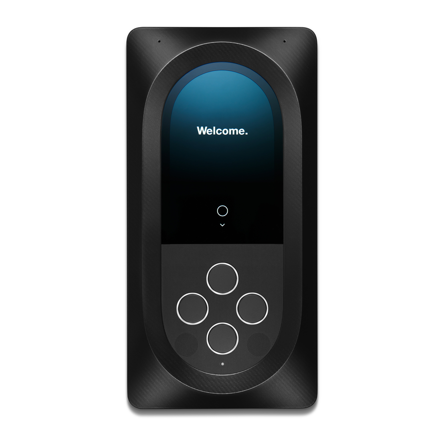
- Page 8 Product Details Mounting Plate Microphone Microphone Centerline Mark Procedural Numbers Display Centerline Mark Navigational Buttons Support Cable Hook Speaker Mesh Security Screw Note: Refer to ADA Guidelines on mounting height. Intercom Installation Guide Version 1.0...
-
Page 9: Specifications
Specifications Dimensions Display • 12.82in (32.6cm) x 6.53in (16.6 cm) x 1.38in (3.5cm) • Brightness: 1000 nits • Viewing angle: 176 degrees Network • 7-inch diagonal Corning® Gorilla® Glass 3 screen • Anti-reflective and anti-fingerprint coating • Ethernet: 10/100/1000 • Bluetooth: BLE 4.2 (iOS and Android compatible) Environmental •... -
Page 10: Installation
Installation Follow these steps to proceed with installation. Intercom Installation Guide Version 1.0... - Page 11 Align the center mark on the mounting plate and center on wall. Level and mark holes 1 and 2. Drill, anchor, and screw in place. Note: Hole 2 is slotted for adjustments. Intercom Installation Guide Version 1.0...
- Page 12 Find the center of the 1.5 inch cable bore hole using marks as a guide. Temporarily remove the mounting plate and drill a 1.5 inch Drill and set anchors for remaining holes 3-6. Reinstall the hole. mounting plate. Intercom Installation Guide Version 1.0...
- Page 13 Important: Keep the protective bumpers on. Align pocket in the bumper with the lower mounting plate tab. Using the support cable, hook the Intercom to the mounting plate for easier wiring. Place the loop of support cable over hook. Intercom Installation Guide Version 1.0...
- Page 14 Female RJ45 Male RJ45 Connector Seal Split Gland Cable Seal Step 1: Feed B through C and E You may use an Ethernet cable to provide both power and Step 2: Plug B into A internet to the device. Or you may utilize the direct power wires Step 3: Connect A to C by twisting.
- Page 15 Use the center alignment pins Important: Ensure cables are dry and free of moisture before to locate the product. Place the Latch Intercom flush with the connecting. mounting plate and slide down until all mounting tabs fit snugly.
- Page 16 Incorrect Correct Note: We recommend forming a drip loop of cables to help avoid moisture condensation on connections or device. Lock into place with the TR20 security screw. Intercom Installation Guide Version 1.0...
-
Page 17: Handling Information
Magnetic Fields The device may induce magnetic fields near the surface of the device strong enough to affect objects such as credit cards and storage media. Download the Latch Manager App and configure. Intercom Installation Guide Version 1.0... -
Page 18: Requirements For Compliance
Regulatory Compliance Federal Communications Commission (FCC) Compliance Statement potential for harmful interference to co-channel mobile satellite systems. This device complies with part 15 of the FCC Rules. Operation is subject to the following two Radiation Exposure Statement conditions: (1) This device may not cause harmful interference, and (2) this device must accept any interference received, including interference that may cause undesired operation. - Page 19 Further configuration information can be found on the support website at support.latch.com • Latch Intercom has been tested for UL294 compliance employing firmware version INT1.3.9 • The current firmware version can be checked by using the Latch Manager app Intercom Installation Guide Version 1.0...
- Page 20 Intercom Installation Guide Version 1.0...
Need help?
Do you have a question about the INT1LFCNA1 and is the answer not in the manual?
Questions and answers