Table of Contents
Advertisement
Advertisement
Table of Contents

Summary of Contents for latch R Series
- Page 1 I N S T A L L A T I O N G U I D E R S E R I E S...
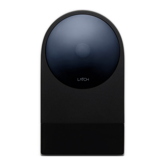
- Page 2 Welcome to your smartest install yet. Latch R is a proximity reader, keypad, and wireless entry system, that can be operated as a standalone device or be connected to a panel as part of a wider system.
-
Page 3: Things You Should Know
Things you should know Only use screws provided. Other screws can cause Latch R to disengage from the mounting plate. The relay will revert to an open state in the event of power failure. Take precautions when wiring fail-safe locking hardware. - Page 4 Wiring Standalone Wiring 12VDC - 24VDC Supply LATCH R Reader A/D0 B/D1 COM_GND NO/NC RJ45 Plug Minimum Wiring Recommendations Distance < 50ft < 200ft < 500ft < 1000ft 22AWG 20AWG 18AWG 14AWG Power 22AWG 20AWG 20AWG 20AWG Relay 22AWG 20AWG...
- Page 5 Request to Exit Egress sensor Door contact sensor Door Lock Router...
- Page 6 Wiring Panel Wiring 12VDC - 24VDC Supply LATCH R Reader A/D0 B/D1 COM_GND NO/NC RJ45 Plug Minimum Wiring Recommendations Distance < 50ft < 200ft < 500ft < 1000ft 22AWG 20AWG 18AWG 14AWG Power 22AWG 20AWG 20AWG 20AWG Wiegand (Shielded) 22AWG...
- Page 7 Door Lock Access Control Panel Unlock + Egress sensor Egress sensor Wiegand/RS-485 Door contact sensor Elevator Control Panel (only when using with Elevator Floor Access) Router...
- Page 8 Wiring Standard Reader Connections Wire Color Name Description RS-485 A, Wiegand DATA0 GREEN A/D0 RS-485 B, Wiegand DATA1 WHITE B/D1 GRAY COM_GND Return for A/D0, B/D1 wires Relay contact YELLOW NO/NC Relay contact BLUE Input/Output ORANGE Input/Output PURPLE Input/Output BROWN 12VDC to 24VDC power input Return for power input BLACK...
- Page 9 Rating Reference 0.025A max drive, 5VDC COM_GND 0.025A max drive, 5VDC COM_GND 1.5A max, 24V DC 1.5A max, 24V DC 0.35A max sink, 24VDC max 0.35A max sink, 24VDC max 0.35A max sink, 24VDC max 0.5A /12VDC or 0.25A /24VDC Voltage difference between GND and COM_GND should not exceed 25V...
-
Page 10: Technical Specifications
Technical Specifications Mechanical - Dimensions: 5.49” x 3.18” x 0.76” Wireless Communication - Near Field Communication (NFC): ISO 14443A - NFC Card Type: Mifare Classic - Bluetooth: BLE 4.2 (iOS and Android compatible) - Wi-Fi: 802.11 b/g/n Wired Communication - Ethernet 10/100Mbps, RJ45 Plug - Serial: RS-485, 5VDC - Wiegand (26-bit) Data0, Data1, 5VDC 25mA source each Power... -
Page 11: Warranty
Interface - 1 x Lock Relay: Configurable SPST NO - 3 x Input or Output (input: normally low; output: open drain) Camera - 135 degree wide capture Environmental - Temperature: Operating / Storage -40°C to 66°C - Operating Humidity: 93% at 32°C, non-condensing - Environmental: IP65 | IK04 Compliance - FCC Part 15 (US) - Page 12 Drill Prepare holes using mounting plate as a template and drill.
- Page 13 Screw Important: Use the provided screws or #6 flathead screws to avoid mounting failure. Screw mounting plate in using the correct screws.
- Page 14 Connect Connect based on wiring diagrams.
- Page 15 Configure Download Latch Manager App from the iOS App Store to configure Latch R and test that everything works. Requires iPhone 5S or newer. Learn more at support.latch.com...
- Page 16 Mount A. Insert bottom locking tab of mounting plate into Latch R. B. Place Latch R flush with mounting plate and slide down until all mounting tabs fit snugly.
- Page 17 Secure Tighten security screw to secure.
-
Page 18: Regulatory Compliance
Regulatory Compliance Federal Communications Commission (FCC) Compliance Statement This device complies with part 15 of the FCC Rules. Operation is subject to the following conditions: (1) This device may not cause harmful interference and (2) this device must accept any interference received, including interference that may cause undesired operation. - Page 19 • Connect the equipment into an outlet on a circuit different from that to which the receiver is connected • Consult the dealer or an experienced radio/TV technician for help Industry Canada (IC) Compliance Statement Operation is subject to the following two conditions: 1.
-
Page 20: Safety Instructions
The product is intended to be used as either a standalone access • control system or as a reader with a panel. Multiple Latch R devices cannot be used to control a single access point. Locations and wiring methods shall be in accordance with the •... -
Page 21: Electronic Specifications
The Latch app is necessary for BLE unlocks and the manager app • is necessary to configure the Latch R. The device using the Latch app to unlock the product can only be • used in the same manner as a physical credential, transmitting user data to the reader interface within close proximity. - Page 22 Latch R has been tested for UL294 compliance employing firmware • version R2.2.1. • The current firmware version can be checked by using the Latch Manager app. • Further programming information can be found on the support website at support.latch.com.
-
Page 23: Request-To-Exit
Keypad LEDs illuminated. For controlled, protected, and/or restricted areas, access control on • a user basis can be configured with the Latch Manager application. The keypad activates when a finger is detected and serves as a • touch screen input to enter passcodes for unlocking the device. - Page 24 Configuration & Commissioning Instructions Configuration & Commissioning instructions can be found in more detail in the Technical Certification Training as well as on the support website at support.latch.com. Service Information Service Information can be found in more detail in the Technical Certification Training as well as on the support website at support.latch.com.
- Page 26 Document Number: 770-00010 v1.6 Revised On: 05/07/2020...


Need help?
Do you have a question about the R Series and is the answer not in the manual?
Questions and answers