Advertisement
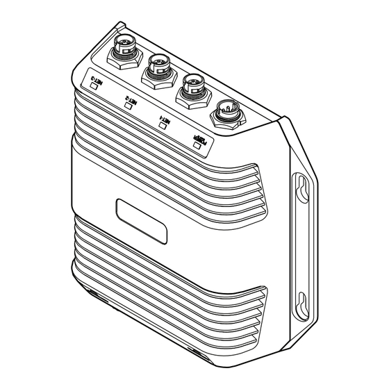
Dimensions
204 mm (8.03")
169 mm (6.63")
TRANSDUCER1
TRANSDUCER2
183 mm (7.20")
Parts included
1
2
3
DESCRIPTION
1
StructureScan® 3D module
2
Installation screws
3
Ethernet cable, 4 m (15 ft)
4
Power cable, 2 m (6.6 ft)
5
Fuse and Fuse holder
6
StructureScan® 3D Transducer (Optional)
57 mm (2.24")
91 mm
180 mm
(3.58")
(7.09")
4
5
6
StructureScan®3D
Installation Guide
207 mm
(8.15")
Mounting
TRANSDUCER1
TRANSDUCER2
For technical specifi cations and
declarations, refer to the product
website on:
lowrance.com
simrad-yachting.com
*988-10970-001*
TRANSDUCER1
TRANSDUCER2
TRANSDUCER1
TRANSDUCER2
Advertisement
Table of Contents

Subscribe to Our Youtube Channel
Summary of Contents for Lowrance SIMRAD StructureScan 3D
- Page 1 204 mm (8.03") For technical specifi cations and 57 mm (2.24") StructureScan®3D 169 mm (6.63") declarations, refer to the product website on: Installation Guide 207 mm (8.15") lowrance.com simrad-yachting.com 91 mm 180 mm (3.58") (7.09") TRANSDUCER1 TRANSDUCER2 *988-10970-001* 183 mm (7.20")
- Page 2 Power Wiring example Multi-Function Displays 4G Radar Power controlled by External Switch Power controlled by Multi-Function Display To Multi-Function Display Black Black Black Yellow Yellow Blue Yellow (n/c) Switch Blue Blue (n/c) Power (n/c) Control bus 12 / 24 V DC StructureScan®...
Need help?
Do you have a question about the SIMRAD StructureScan 3D and is the answer not in the manual?
Questions and answers