Table of Contents
Advertisement
D A N G E R
Si no entiende ingles, se prefiere que
busque a alguien que interprete las
instrucciones para usted.
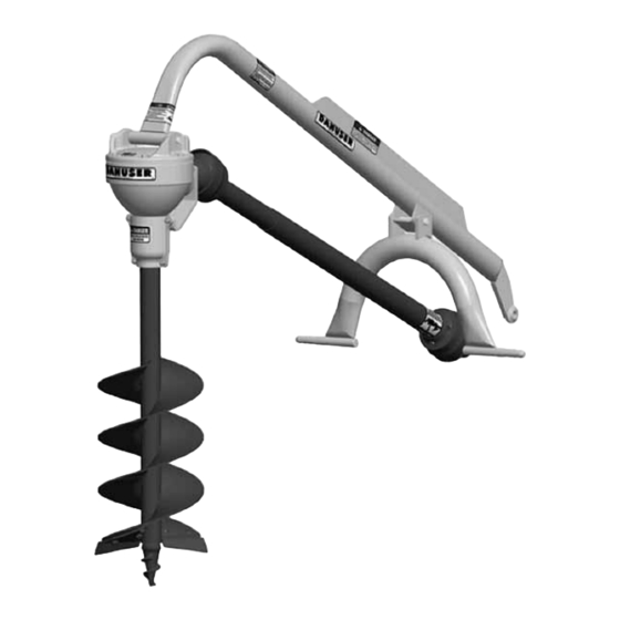
G20/40
Made in the U.S.A.
Owner:
Date Purchased:
G20/40
Model #:
Serial #:
9MG20402454105
Manual #:
Owner's Manual
Danuser Machine Company, Inc.
500 East Third Street
P.O. Box 368
Fulton, Missouri 65251
Tel: (573) 642-2246
E-mail: sales@danuser.com
Website: www.danuser.com
Fax: (573) 642-2240
Advertisement
Table of Contents

Related Manuals for Danuser G20/40


Summary of Contents for Danuser G20/40
- Page 1 G20/40 Model #: Serial #: 9MG20402454105 Manual #: Owner’s Manual Danuser Machine Company, Inc. D A N G E R 500 East Third Street P.O. Box 368 Fulton, Missouri 65251 Si no entiende ingles, se prefiere que Tel: (573) 642-2246...
- Page 2 “Good enough won’t do - it must be right.” ince 1910 Today, a new modern plant built by my father, Henry Danuser, is located on the original site. This building and those who work in it are dedicated to the tradition of fine craftsmanship and to the production of quality implements.
-
Page 3: Table Of Contents
Warranty Registration Your WARRANTY REGISTRATION FORM & INSPECTION REPORT serves two purposes: it activates warranty coverage; and it allows Danuser to notify you, the owner, of improvements to the equipment or of new safety features that may be retrofitted to previously sold diggers. -
Page 4: Safety
If there is anything in this manual you do not understand, contact your dealer or Danuser Machine Company, Inc. The safe use of this machine is strictly up to you, the operator. If this unit is used, loaned, or rented by any other person, it is the owner's responsibility to make certain that the operator prior to operating: •... - Page 5 Safety • Only properly trained people should operate this equipment. Do not allow anyone who has not read this entire manual and understood the safety rules, safety signs, and operation instructions to use this digger. (continued) • Never allow children to operate or be around this post hole digger. •...
- Page 6 Older machines can be retrofitted to add these safety signs and shields or guards. If you have an older Danuser post hole digger which does not have current standard safety equipment, please contact your dealer about bringing your machine up to the current level of safety.
-
Page 7: Preparation
(Fig. 1) and shipping list (Table 1) below to ensure you have all of the components and your unit has all of the safety signs and shields or guards required by current production safety standards. If your unit does not comply, contact Danuser Machine Company, Inc. IMMEDIATELY at (573) 642-2246. -
Page 8: Assembly & Installation
Assembly & Description The G20/40 Digger is built to the exacting standards of high quality which have become Installation synonymous with the name Danuser. The G20/40 Digger is designed for one-man operation from the tractor seat to “Dig Holes Sitting Down.” The heat-treated straight bevel gear set,... - Page 9 Assembly & Instructions (Refer to Fig. 2.) Installation C A U T I O N Because of the weight of some components, and because (continued) some components are difficult to balance, two people are required for safe assembly and installation of this equipment.
- Page 10 STEP 8: Grease the inside of the auger adapter liberally, and attach the auger with the Danuser 1/2" 13 x 3-1/4" (1/2" of thread) special retaining bolt (PN 6014) and nut (PN 1056). NEVER use a bolt longer than 3-1/4".
-
Page 11: Installation Troubleshooting
Assembly & STEP 12: Install the Auger Adapter Shields (PN 6137) around the auger adapter and secure to the guard bracket (PN 6274) with two bolts (PN 1180) and two nuts Installation (PN 2168). Install two bolts (PN 2339) and two nuts (PN 2168) in the bottom two holes of the Auger Adapter Shields. -
Page 12: Operation
Read and understand this Owner's Manual carefully before attempting to operate or adjust the Danuser G20/40 Digger. You are responsible for furnishing this manual to others who may use the unit. If you have any questions regarding the proper assembly, installation, or operation of this digger, contact your dealer or Danuser Machine Company, Inc. - Page 13 (25') around the auger clear of bystanders and all other people. W A R N I N G STEP 11: If you break a shear bolt, the roll pin should retain the driveline on the G20/40 Replace a broken or Digger pinion. Replace the special shear bolt as follows:...
-
Page 14: Difficult Digging Suggestions
Operation D A N G E R (continued) Keep others at least twenty-five feet (25') from the auger when applying lift power to raise the freed auger from the ground. Stop auger rotation prior to lifting out of hole. STEP 12: If the auger becomes lodged on an obstruction below ground, do not attempt to raise the auger by hydraulic lift power alone. -
Page 15: Decals & Safety Signs
Decals & Safety Signs PART NO. PHDC 2 Location: Boom, left side PART NO. PHDC 3 Location: Boom, right side PART NO. PHDC 1 Location: Boom, rear, above gearbox PART NO. PHDC 4 Location: Boom rib, right side SERIAL NUMBER Location: Gearbox, lid PART NO. -
Page 16: Digger Parts
Shear Bolt (5/16" 18 x 2-1/4" Gr. 5, 13/32" of thread) ..6015 * ..3 (SPECIAL BOLT: Use Genuine Danuser Replacement Only) Nut (5/16" 18) ........573 * ..3 Pin (3/4"... -
Page 17: Gearbox Assembly
Spindle Assembly ....6352 ..1 Danuser Decal ....2088 ..1 Auger Adapter Shield . -
Page 18: Driveline Parts
Driveline Parts G20/40 DRIVELINE PARTS = Safety Sign Location Ref. Part. No. Description Req’d Driveline ..... . .6814 ..1 Telescoping Assembly with Guard Digger Half with Guard . -
Page 19: Auger Assemblies
As Req’d Retaining Bolt (1/2" 13 x 3-1/4" Gr. 8, 1/2" of thread) 6014 6014 6014 6014 6014 6014 6014 6014 SPECIAL BOLT: Use Genuine Danuser Replacement Only 1056 1056 1056 1056 1056 1056 1056 1056 Retaining Nut (1/2" 13 Hex) 6080G 6080G 6080G 6080G 6080G 6080G 6080G 6080G Auger Extension with Guard (7") -
Page 20: 2" Round Augers
2” Round Augers = Safety Sign Location 2" ROUND SPINDLE AUGERS Part Number by Auger Diameter Description 4" 6" 9" 12" 14" 16" 18" 24" 6101 6029 6030 6032 6034 6036 6038 6040 40" Long with Plain Edges & Standard Point 6031 6033 6035... -
Page 21: Hole Digger Head Auger Assemblies
40" Hole Depth Auger with Double Flight Construction Retaining Bolt (1/2" 13 x 3-1/4" Gr. 8, 1/2" of thread) 6014 6014 6014 6014 6014 SPECIAL BOLT: Use Genuine Danuser Replacement Only 1056 1056 1056 1056 1056 Retaining Nut (1/2" 13) -
Page 22: Accessories
Accessories Standard Special Duty Aggressive Duty AUGER POINTS Ref. Part Description Standard for augers 6" through 24" diameter ..831 only point for 4" augers ....899 Special Duty . - Page 23 (continued) A Down Force Kit (PN 6220) is available to make difficult digging easier. The kit attaches to all G20/40 Diggers without alteration and with the use of ordinary hand tools. It provides approximately 500 pounds of additional force to the auger point for easier penetration of hard or frozen ground.
- Page 24 This page is intentionally blank.
-
Page 25: Warranty
This Warranty is extended only to the original purchaser of our products. Danuser Machine Company, Inc. warrants this product to be free from defects in material and workmanship for a period of one year from the purchase date from an authorized Danuser Dealer. The Serial # gearbox warranty can be extended to five years if the WARRANTY REGISTRATION FORM &... -
Page 26: Important Safety Message For Owners/Operators
Be careful and make sure that everyone who operates the digger knows and understands that it is a very powerful piece of machinery, and if used improperly, serious injury or death may result. The final responsibility for safety rests with the operator of this machine. DANUSER MACHINE COMPANY, INC. Fulton, Missouri 65251-0368 Form No. 3027...
Need help?
Do you have a question about the G20/40 and is the answer not in the manual?
Questions and answers