Table of Contents
Advertisement
Available languages
Available languages
g g lobalindustrial.ca
Distribucion Industrial Globales S DE RL
DE CF
Assembly Instructions
Instrucciones de Ensambla
aje
Dir
ectives d'assemblage
Customer Service
Servicio de atención al Clien
nte
Service à la clientèle
México: 01.800.681.6940
Canada: 888-645-2986
US: 1-800-645-2986
Electric
Blower He
eater
Models: 653561 653560 6535
559
Wall Mount Models: 653566 653567 653568
653558 653562 246067
653569 246068
READ & SAVE
THESE
INSTRUCTIO
ONS
1
050117
Advertisement
Table of Contents

Subscribe to Our Youtube Channel
Related Manuals for Global 653561

Summary of Contents for Global 653561
- Page 1 Servicio de atención al Clien Service à la clientèle México: 01.800.681.6940 Canada: 888-645-2986 US: 1-800-645-2986 Electric Blower He eater Models: 653561 653560 6535 Wall Mount Models: 653566 653567 653568 653558 653562 246067 653569 246068 READ & SAVE THESE INSTRUCTIO 050117...
-
Page 2: Important Instructions
Product Specifications Product Specifications Model 653558 653559 653560 653561 653562 246067 Model 653558 653559 653560 653561 653562 246067... -
Page 3: Wiring Diagrams
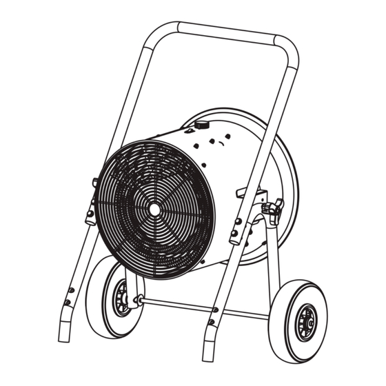
Overheat Overheat Thermostat Thermostat Protection Protection Motor Motor Light Light Tip over switch Tip over switch Fan Switch Fan Switch 653560 653567 653561 653568 653560 653561 L2 L3 240V/60Hz/1P 240V/60Hz/3P 15KW 15KW Overheat Overheat Thermostat Thermostat Protection Protection Motor Motor... - Page 4 Electric Blower Heater Assembly Instructions PARTS LIST A. Handle B. Heater Housing C. Tilt Adjustable Knob D. Wheel E. Front Exhaust Grill F. On/Off Switch G. Temperature Setting Knob Cart-Stand A. Wall Mount Bracket B. Hanger C. Heater Housing D. Front Exhaust Grill E.
-
Page 5: Installation Instructions
Electric Blower Heater User’s Manual INSTALLATION INSTRUCTIONS CAUTION WARNING Keep electrical cords, drapery, furnishings and other combustibles All wiring must be installed by a certified at least 3 feet (0.9 m) from heater, electrician in accordance with electrical to prevent risk of fire. safety standards. - Page 6 Electric Blower Heater User’s Manual Use M8 x 80 screw (10), 8mm ID washer (9), and M8 nut (8) to attach Use M8 x 80 screw (10), 8mm ID handle to foot stand. Tighten. washer (9), and M8 nut (8) to attach handle to foot stand.
-
Page 7: Maintenance And Cleaning
All Models are designed to automatically shut off SAFETY TIP-OVER SWITCH when heater is tipped sideways. Place unit on level Models 653558, 653559, 653560 and 653561 are surface to prevent tipping. designed to automatically shut off when heater is tipped sideways. -
Page 8: Wiring Instructions
L1: White live wire L2: Black live wire to terminals. FOR 3 PHASE MODELS: Models 653561 653562 246067 1. Open the wiring cover. 2. Connect the red live wire to L1, black live wire to L2 and white live wire to L3 of the connector. - Page 9 Servicio de atención al Clien Service à la clientèle US: 1-800-645-2986 México: 01.800.681.6940 Canada: 888-645-2986 Calentador De Aire E léc trico Modelos: 653561 653560 653 3559 Wall Mount Modelos: 653566 653567 653568 653558 653562 246067 653569 246068 LEA Y CONSE ERVE ESTAS INSTRUCC CIONES...
- Page 10 Especificaciones del Producto Especificaciones del Producto Modelo 653558 653559 653560 653561 653562 246067 Modelo 653558 653559 653560 653561 653562...
-
Page 11: Instrucciones De Ensamblaje
Protección Sobrecalentamiento Motor Motor Astuce commutateur Interruptor Ventilador Astuce commutateur Astuce commutateur Interruptor Ventilador Interruptor Ventilador Astuce commutateur Interruptor Ventilador 653560 653567 653561 653568 653560 653561 L2 L3 240V/60Hz/1P 240V/60Hz/3P 15KW 15KW El poder del bloque de terminales Protección Protección... - Page 12 Instrucciones de Ensamblaje Calentador De Aire Eléctrico LISTA PARTES A. Manilla B. Carcasa Calentador C. Perilla Ajuste Inclinación D. Rueda E. Rejilla Escape Frontal F. Conmutador On/Off G. Perilla Configuración Temperatura Pedestal Carro A. Soporte mural B. Colgador C. Carcasa Calentador D.
- Page 13 Calentador De Aire Eléctrico Manual del usuario INSTRUCCIONES DE INSTALACIÓN PRECAUCIÓN ADVERTENCIA Mantenga los cables eléctricos, cortinas, muebles y otros combustibles Todo el cableado debe ser instalado por un por lo menos 3 pies (0,9 m) de calentador, técnico electricista certificado, en conformidad para prevenir el riesgo de incendio.
-
Page 14: Manual Del Usuario
Calentador De Aire Eléctrico Manual del usuario Use el tornillo M8 x 80 (10), la arandela de 8mm (9) y la tuerca M8 (8) para fijar Use el tornillo M8 x 80 (10), la arandela la manija al soporte de pie. Apriete. de 8 mm (9) y la tuerca M8 (8) para fijar la manija al soporte de pie. -
Page 15: Mantenimiento Y Limpieza
Todos los modelos están diseñados para apagarse INTERRUPTOR DE SEGURIDAD automáticamente cuando el calentador se incline hacia Los modelos 653558, 653559, 653560 y 653561 están los lados. Coloque la unidad en una superficie plana diseñados para apagarse automáticamente cuando el para evitar que esto suceda. -
Page 16: Instrucciones De Cableado
L1: Cable blanco con corriente L2: Cable negro con corriente cables para conectar las terminales. PARA LOS MODELOS DE FASE 3: Modelos 653561 653562 246067 1. Abra la cubierta del cableado. 2. Conecte el cable rojo con corriente al L1, el cable negro con corriente al L2 y el cable blanco con corriente al L3 del conector. - Page 17 Servicio de atención al Clien Service à la clientèle México: 01.800.681.6940 Canada: 888-645-2986 US: 1-800-645-2986 Ventilateur Électrique Chauffant Modèles: 653561 653560 653 3559 Wall Mount Modèles: 653566 653567 653568 653558 653562 246067 653569 246068 LIRE ET SAUVEG GARDER CES INSTRUCT...
-
Page 18: Instructions Importantes
Éviter l’utilisation de rallonge ou de multiprise en raison d’une assurez-vous que le chauffeur soit inspecté par un électricien qualifié surchauffe et risque d’incendie. avant de le réutiliser. Spécifications du produit Spécifications du produit Modèle 653558 653559 653560 653561 653562 246067 Modèle 653558 653559 653560 653561 653562 246067 Wall Mount Modèle... -
Page 19: Directives D'assemblage
Lumière Lumière Lumière Moteur Lumière Tip-commutateur Tip-commutateur Tip-commutateur Commutateur Fan Tip-commutateur Commutateur Fan Commutateur Fan Commutateur Fan 653560 653567 653561 653568 653560 653561 L2 L3 240V/60Hz/1P 240V/60Hz/3P 15KW 15KW Power terminal block Protection Thermostat Protection Thermostat Thermostat Protection... - Page 20 Directives d’assemblage Ventilateur Électrique Chauffant LISTE DES PIÈCES A. Poignée B. Boitier du réchauffeur C. Inclinez bouton réglable D. Roue E. Échappement avant de la grille F. Interrupteur ON/OFF G Bouton de réglage température Montage de panier A. Support mural B.
-
Page 21: Instructions D'installation
Ventilateur Électrique Chauffant Manuel de l'utilisateur INSTRUCTIONS D'INSTALLATION MISE EN GARDE AVERTISSEMENT Gardez les cordons électriques, draperie, meubles et autres combustibles Tout le câblage doit être installé par un au moins 3 pieds (0,9 m) du réchauffeur, électricien certifié conformément aux pour prévenir le risque d'incendie. -
Page 22: Manuel De L'utilisateur
Ventilateur Électrique Chauffant Manuel de l'utilisateur Utiliser la vis M8 x 80 (10), la rondelle au diamètre de 8mm (9), et l’écrou M8 (8) pour Utiliser la vis M8 x 80 (10), la rondelle fixer la poignée au pied. Serrer. au diamètre de 8 mm (9), et l’écrou M8 (8) pour fixer la poignée au pied. -
Page 23: Maintenance Et Nettoyage
Tous les modèles sont conçus pour arrêter COMMUTATEUR DE SÉCURITÉ - INTERRUPTEUR automatiquement squalor le chauffeur est basculé sur Les modèles 653558, 653559, 653560 et 653561 le côté. Placez l’unité sur une surface plane pour sont conçus pour arrêter automatiquement squalor le éviter tout renversement. -
Page 24: Dépannage
L1 : Fil sous tension blanc L2 : Fil sous tension noir de la connexion aux bornes. POUR LES MODÈLES À 3 PHASES Modèles 653561 653562 246067 1. Ouvrez le couvercle du câblage. 2. Brancher le fil des rouges au bornier L1, le fil noir sous tension au bornier L2 et le fil blanc sous tension au bornier...
Need help?
Do you have a question about the 653561 and is the answer not in the manual?
Questions and answers