Table of Contents
Advertisement
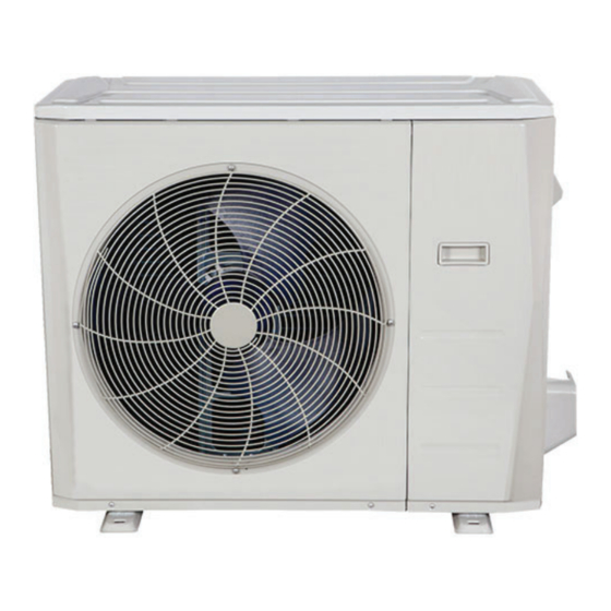
Outdoor Unit Single Zone Ductless System - Sizes 36 to 48
Fig. 1 -Size 36K
Fig. 2 -Size 48K
NOTES: Read the entire instruction manual before starting the
installation.
Images are for illustration purposes only. Actual
models may differ slightly.
DLCLRB
INSTALLATION INSTRUCTIONS
Specifications subject to change without notice.
TABLE OF CONTENTS
SAFETY CONSIDERATIONS........................................................2
INTRODUCTION ............................................................................3
ACCESSORIES................................................................................3
DIMENSIONS..................................................................................4
CLEARANCES ................................................................................6
INSTALLATION REQUIREMENTS .............................................7
INSTALLATION .............................................................................7
Step 1 - Check Equipment ................................................................7
Step 2 - Mount Unit ..........................................................................7
Step 3 - Condensate Drain Installation .............................................8
Step 4 - Refrigerant Piping ...............................................................9
Step 5 - Evacuate Coil And Tubing System .....................................12
Step 6 - Electrical Connections.........................................................13
WIRING ...........................................................................................13
ELECTRICAL DATA......................................................................14
CONNECTION DIAGRAMS ..........................................................14
START-UP .......................................................................................15
CARE AND MAINTENANCE........................................................15
OUTDOOR UNIT DIAGNOSTIC GUIDES ...................................15
DUCTLESS START-UP CHECKLIST ...........................................16
Page
Advertisement
Table of Contents

Related Manuals for CMNA DLCLRB Series

Summary of Contents for CMNA DLCLRB Series
-
Page 1: Table Of Contents
DLCLRB INSTALLATION INSTRUCTIONS Outdoor Unit Single Zone Ductless System - Sizes 36 to 48 TABLE OF CONTENTS Page SAFETY CONSIDERATIONS............2 INTRODUCTION ................3 ACCESSORIES................3 DIMENSIONS..................4 CLEARANCES ................6 INSTALLATION REQUIREMENTS ..........7 INSTALLATION ................7 Step 1 - Check Equipment ..............7 Step 2 - Mount Unit ................7 Step 3 - Condensate Drain Installation ..........8 Step 4 - Refrigerant Piping ...............9 Fig. -
Page 2: Safety Considerations
SAFETY CONSIDERATIONS WARNING Installing, starting up, and servicing air- conditioning equipment can be hazardous due to system pressures, electrical components, and equipment location (roofs, elevated structures, etc.). ELECTRICAL SHOCK HAZARD Only trained, qualified installers and service mechanics should Failure to follow this warning could result in personal injury or install, start- up, and service this equipment. -
Page 3: Introduction
INTRODUCTION The Horizontal Discharge Outdoor units are R-410A condensing units designed with application flexibility in mind. These units have a max total piping length up to 213 ft (65 m) and a maximum piping lift of up to 98 ft (30m). The inverter driven compressor is designed to run at various input power frequencies (Hz) which controls the compressor’s motor speed. -
Page 4: Dimensions
DIMENSIONS Table 3 — Dimensions UNIT SIZE Height in (mm) 31.89 (810) 52.48 (1333) Width in (mm) 37.24 (946) 37.48 (952) Depth in (mm) 16.14 (410) 16.34 (415) Operating Weight lbs (kg) 155.42 (70.5) 219.14 (99.4) Shipping Weight lbs (kg) 166.23 (75.4) 249.12 (113) Shipping Height... - Page 5 DIMENSIONS (CONT.) Size 48K Fig. 5 —Size 48K 32801100001 Specifications subject to change without notice.
-
Page 6: Clearances
CLEARANCES Air inlet Air outlet Fig. 6 — Outdoor Unit Clearances Table 4 — Outdoor Unit Clearance Dimensions MINIMUM VALUE UNIT IN. (MM) 24 (610) 24 (610) 24 (610) 4 (101) 4 (101) 19in (48cm) or more on a multiple parallel unit arrangement 4in (10cm) or more on a single parallel unit arrangement... -
Page 7: Installation Requirements
INSTALLATION REQUIREMENTS INSTALLATION • A location which is convenient to installation and not exposed to Step 1 - Check Equipment strong winds. Unpack the unit and move to the final location. Remove the carton, • A location which can bear the weight of the outdoor unit and where the outdoor unit can be mounted in a level position. -
Page 8: Step 3 - Condensate Drain Installation
Step 3 - Condensate Drain Installation CAUTION Install drains must meet local sanitation codes. Install the outdoor unit drain joint EQUIPMENT DAMAGE HAZARD Fit the seal into the drain joint, then insert the drain joint into the base In cold climates, ensure the drain hose is as vertical as possible to pan hole of the outdoor unit. -
Page 9: Step 4 - Refrigerant Piping
Step 4 - Refrigerant Piping Table 6 — Piping and Refrigerant Information SYSTEM SIZE Min. Piping Length ft (m) 10 (3) 10 (3) Standard Piping Length ft (m) 25 (7.5) 25 (7.5) Max. outdoor - indoor height difference (OU higher than IU) ft (m) 98 (30) 98 (30) - Page 10 Use the following steps to connect the refrigerant piping: 5. Flare Pipe Ends Proper flaring is essential to achieving an airtight seal. 1. Run the interconnecting piping from the outdoor unit to the indoor a. After removing the burrs from the cut pipe, seal the ends with unit.
- Page 11 NOTE: Use both a backup wrench and a torque wrench when 6. Connect the Pipes connecting or disconnecting pipes to or from the unit. Connect the copper pipes to the indoor unit first, then connect the pipes to the outdoor unit. Connect the low-pressure pipe first, then connect the high pressure pipe.
- Page 12 Step 5 - Evacuate Coil And Tubing System Evacuation Evacuation of the system will remove air or nitrogen (non-condensables) CAUTION as well as moisture. A proper vacuum will assure a tight, dry system before charging with refrigerant. The two methods used to evacuate a system are the deep vacuum method and the triple vacuum method.
-
Page 13: Step 6 - Electrical Connections
Step 6 - Electrical Connections WIRING All wires must be sized per NEC (National Electrical Code) or CEC Install All Power and Interconnecting Wiring to (Canadian Electrical Code) and local codes. Use Electrical Data table MCA Outdoor Units (minimum circuit amps) and MOCP (maximum over current protection) to correctly size the wires and the disconnect fuse or breakers respectively. -
Page 14: Electrical Data
ELECTRICAL DATA Table 10 — Electrical Data OUTDOOR UNIT SIZE 208/230 - 1 - 60 208/230 - 1 - 60 Max – Min* Oper. Voltage 253 - 187 253 - 187 Power Supply 36.5 MOCP Volts- PH- Hz 208/230 - 1 - 60 208/230 - 1 - 60 Compressor 23.5... -
Page 15: Start-Up
START-UP Test Operation Perform a test operation after completing a gas leak and electrical safety check. See the indoor unit installation instructions and owner's manual for additional start up information. System Checks 1. Conceal the tubing where possible. 2. Make sure that the drain tube slopes downward along its entire length. 3. -
Page 16: Ductless Start-Up Checklist
DUCTLESS START-UP CHECKLIST Installation Data Site Address:_______________________________________________________________________________________________________ City:________________________________________________________ State:___________ Zip Code:__________________ Installing Contractor:______________________________________________________ Contractor Contact #: ( ) _____-___________ Job Name:_______________________________________________________________ Start-up Date:_____________________________ Distributor:_______________________________________________________________ System Details UNITS MODEL NO. SERIAL NO. CONTROLLER OUTDOOR UNIT INDOOR UNIT A Wiring Electrical Wire Size and Type Used? AWG:__________ TYPE:_________ Are there any breaks, splices, wire nuts or butt connectors between the outdoor unit and the indoor door unit? YES:______ NO:______ Was the wiring from the outdoor unit port to the correct indoor unit verified? - Page 17 Ductless Start-Up Checklist (CONT) Piping Leak Check: System held 500 psig (max. 550psi) for a minimum of 30 minutes using dry nitrogen. YES:______ NO:______ Evacuation Method: • YES:______ NO:______ Was the Triple Evacuation Method used as outlined in the installation manual? •...
- Page 18 Copyright 2020 CMNA 3300 Riverwood Parkway Atlanta GA 30339 32801100001...
Need help?
Do you have a question about the DLCLRB Series and is the answer not in the manual?
Questions and answers