
Subscribe to Our Youtube Channel
Related Manuals for Accu-Sort 10


Summary of Contents for Accu-Sort 10
- Page 1 Model 10 Bar Code Scanner PERATIONS AND AINTENANCE ANUAL Revision: 1.1 Release Date: 01/23/01...
- Page 3 NTRODUCTION This is the Operations and Maintenance Manual for the Model 10. It provides details on everything you need to know to unpack, set up, operate, maintain, and troubleshoot your system. This note box is used throughout this manual to indicate supplementary information important to the current topic.
- Page 4 If the defective unit is not returned within 30 days, the customer will be contacted. If the defective unit is not returned after 45 days, the customer will be invoiced for that unit. Accu-Sort will issue an RA# (return authorization number) for each defective unit.
-
Page 5: Model 10 Serial Tag
USTOMER ERVICE If you have any problems or questions that require Accu-Sort’s help, direct your calls to the Customer Service Department. Accu-Sort Customer Service: phone: (215) 723-0981 1-800-BAR-CODE (ask for Customer Service) fax: (215) 723-1515 To ensure that Accu-Sort’s response is prompt and accurate, please have the... - Page 6 AFETY ECOMMENDATIONS AND RECAUTIONS The Model 10 is an electronic microprocessor-based bar code scanner. Please follow the safety precautions and warnings found throughout this manual in order to prevent personal injury or damage to the unit. Failure to follow these precautions may void your warranty.
- Page 7 Be certain your hands and the floor of your work area are dry before touching electrical equipment or connecting cords. • Routinely check all connections to your Model 10. If a cable is damaged in any way, replace it. •...
-
Page 8: Model 10 Labels And Locations
ABEL OCATIONS The following labels identify areas of the Model 10 that require special precautions or handling, or provide general information. Model 10 Labels and Locations... -
Page 9: Table Of Contents
Table of Contents Chapter One Introduction ........................1-3 HECKING THE ACKING ................... 1-7 ENERAL ESCRIPTION OF YSTEM PERATION 10 S ....................... 1-9 LOCK IAGRAM OF ODEL YSTEM ......................... 1-10 RODUCT PECIFICATIONS ............................ 1-11 EATURES ............................1-12 HARTS ........................1-12 ENERAL URPOSE .......................... - Page 10 10 O ODEL PERATIONS AND AINTENANCE ANUAL Chapter Six Maintenance ........................... 6-3 AINTENANCE ASKS ......................... 6-3 INDOW LEANING ........................6-3 XTERIOR LEANING .................... 6-3 HECK ONNECTIONS FOR IGHTNESS Chapter Seven Basic Operating Examples ..........................7-3 PPLICATION XAMPLES ......................7-3 ABEL...
- Page 11 HIPKIT ........................3-9 NIVERSAL OUNTING RACKET ......................... 3-10 ALL AND OCKET OUNT & S ......................... 3-11 OCKET OUNT ERMS 10 LED D ........................4-3 ODEL ESCRIPTIONS LED B ....................4-3 EGMENT RAPH ISPLAY .......................... 4-4 EGMENT ALUES .......................... 4-5 EGMENT ALUES ........................
- Page 12 10 O ODEL PERATIONS AND AINTENANCE ANUAL Accu-Sort Systems...
-
Page 13: Chapter One Introduction
Chapter One Introduction 1Heading 2 Chapter One Contents ..............1-3 HECKING THE ACKING ........1-7 ENERAL ESCRIPTION OF YSTEM PERATION 10 S ........... 1-9 LOCK IAGRAM OF ODEL YSTEM ..............1-10 RODUCT PECIFICATIONS ..................1-11 EATURES ..................1-12 HARTS ................1-12... - Page 14 10 O ODEL PERATIONS AND AINTENANCE ANUAL Accu-Sort Systems...
-
Page 15: Checking The Packing Slip
Accu-Sort immediately at 1-800-BAR- CODE (refer to Customer Service). The Model 10 packaging was specifically designed to protect the unit during shipment. Do not throw it away. Save all the packaging materials in case you have to transport your unit to a different building. - Page 16 1000008760 1 Meter, Flying Leads, 15 Conductors OTS Distributor Units 1000025466 General Purpose, 10 mil min, .5@5 Raster, EM (300 Scans/Second) 5VDC 1000025467 General Purpose, 10 mil min, .5@5 Raster, FF (300 Scans/Second) 5VDC 1000025468 General Purpose, 10 mil min, .5@5 Raster, FF (300 Scans/Second) 24VDC 1000025469 High Density, 5 mil min, .5@5 Raster, EM (200 Scans/Second) 5VDC...
- Page 17 1000003656 Ball and Socket Mount Kit 1000018197 Mounting Structure Assembly 1000018208 Mounting Kit Displays 1000016277 External Display 1000016281 External Display w/ 10 Ft. Cable 1000016280 110V External Power Supply for Display 1000016283 220V External Power Supply for Display Solutions with Vision...
-
Page 18: Parts Table
1000017047 Dual Lamp Enclosure Communication Interfaces 1000015450 15 pin port DeviceNet 1000015843 External Serial to Ethernet Converter Kit (Plugs into 15 pin connector on scanner) Model 10 Documentation 1000025606 Small Scanners Installation Software and User Documentation CD-ROM Parts Table Accu-Sort Systems... -
Page 19: General Description Of System Operation
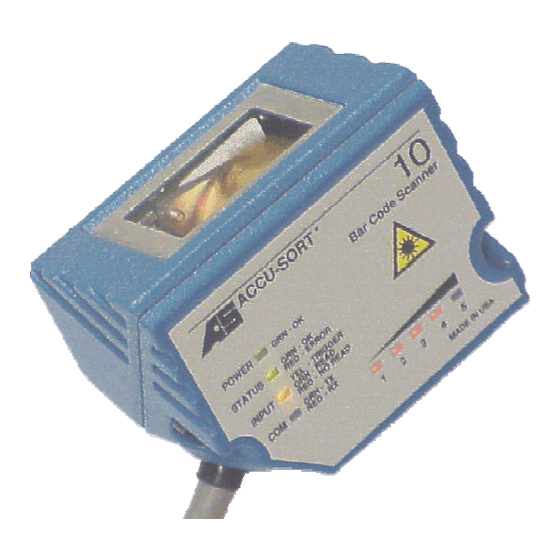
ESCRIPTION OF YSTEM PERATION The Model 10 combines impressive optical performance with useful electrical features in a rugged IP-65 / NEMA 4 rated enclosure. Its compact size, zero clearance cable exit, and flexible software parameters ease integration into existing as well as new designs. -
Page 20: Typical Model 10 Installation
Typical Model 10 Installation (Material Handling) Typical Model 10 Installation (Embedded) The installation of the Model 10 as an embedded laser normally requires that the end product be certified to the regulations of the Center for Devices and Radiological Health (CDRH). -
Page 21: Block Diagram Of Model 10 System
NTRODUCTION 10 S LOCK IAGRAM OF ODEL YSTEM Bottom Label of Model 10 with Model Configuration Solutions with Vision... -
Page 22: Product Specifications
Motor Brushless DC motor Mirror wheel Polygon scanning element, machined aluminum, 6 facets Input power Single 5 volt or 10 to 30 Volt power supply (separate versions) Polarity and over-voltage protected Serial interfaces, RS232 with RTS/CTS support 115.2K baud RS485 Multidrop... -
Page 23: Features
1-11 NTRODUCTION Do not turn on the system until all components are properly cabled and grounded with three-conductor AC power cords. Do not use a two-prong adapter. Do not use an extension cord to defeat the ground. EATURES • Installation simplified •... -
Page 24: Read Charts
AINTENANCE ANUAL HARTS The following charts depict the scanning capabilities of the Model 10 in relation to the optical setup. There are two optical setups available for the Model 10. • A - General Purpose • B - High Density... -
Page 25: High Density
1.5”-3” (38.1-76.2mm) 1.5” (38.1mm) 3.9” (99mm) @ 2.1” (53mm) 7.5 mil (.19mm) 1”-3.5” (25.4-88.9mm) 2.5” (63.5mm) 4.25” (107mm) @ 2.37” (60mm) 10.0 mil (.25mm) 1”-4” (25.4-101.6mm) 3” (76.2mm) 4.8” (122mm) @ 2.6” (66mm) 15.0 mil (.38mm) 1”-4.5” (25.4-114.3mm) 3.5” (88.9mm) 5.6”... - Page 26 1-14 10 O ODEL PERATIONS AND AINTENANCE ANUAL Accu-Sort Systems...
-
Page 27: Chapter Two Configuring The System
Chapter Two Configuring the System 2Heading 2 Contents Chapter Two ..........2-3 IRING AND ERMINATING ONNECTIONS ............2-4 BJECT ENSING IGNAL EVICE... - Page 28 10 O ODEL PERATIONS AND AINTENANCE ANUAL Accu-Sort Systems...
-
Page 29: Cable Pin Configurations
360° connection to the shielded mating connector. You must connect all peripheral equipment before you begin operating the system. Below is a table of the different cable pin configurations for the Model 10: CABLE PIN CONFIGURATION 1000008760 1000008758... -
Page 30: Object -Sensing Signal Device
IGNAL EVICE The Model 10 must be informed when an object on the conveyor is about to enter its reading zone. An object-sensing signal device is typically used to do this. The device is mounted on the conveyor upstream from the Model 10 in relation to conveyor travel. -
Page 31: Chapter Three Installation
Chapter Three Installation 3Heading 2 Chapter Three Contents ..............3-3 NSTALLATION EQUIREMENTS ....................3-3 OWER ..............3-4 OUNTING EQUIREMENTS 10 ................ 3-6 OUNTING THE ODEL ............ 3-6 ULTIPURPOSE OUNTING RACKET ............. 3-8 NIVERSAL OUNTING HIPKIT ..............3-10 ALL AND OCKET OUNT ................ - Page 32 10 O ODEL PERATIONS AND AINTENANCE ANUAL Accu-Sort Systems...
-
Page 33: Installation Requirements
NSTALLATION NSTALLATION EQUIREMENTS OWER There are two supply voltages available for the Model 10: 4.80 - 5.25 Volt • Input range 4.80 to 5.25 VDC, over-voltage and reverse polarity protected • Easily powered from system 5 Volt Bus, Small Scanner Interface, or EM-50. -
Page 34: Mounting Requirements
Install beam blocks at the far side of all conveyor locations to limit the amount of laser light exposure. • Under no circumstances should the Model 10 be mounted in a position that would cause the laser light to be a distraction, or would cause personnel to look into the beam. -
Page 35: Mounting Contact Points
NSTALLATION Mounting contact points provide three points of contact for repeatability. The Model 10 can be removed from its mounting position, and be replaced in the exact same position. The contact points also ensure the Model 10 will rest parallel to the mounting surface. -
Page 36: Mounting The Model 10
ODEL PERATIONS AND AINTENANCE ANUAL OUNTING THE ODEL There are several mounting options for the Model 10. The following tables and diagrams provide the information necessary to mount your Model 10 properly for your application. ULTIPURPOSE OUNTING RACKET Mounting Column with Multipurpose Mounting Bracket... - Page 37 Multipurpose Mounting Bracket Parts List Item Quantity Description Part Number Mount, Model 10/20/22/30 Tilt 1000002333 Rod, Mounting 1000002330 10-32 3/8 Set, Cup Point 1000005795 Block, Mounting 1000002329 T-Nut, 5/16-18 Black 1000018505 5/16-18X5/8 Cap, Button Head Black Hex 1000009218 Block, Pivot...
-
Page 38: Universal Mounting Shipkit
M3 Split Lock Washer 1000019967 The Model 10 can be attached to this bracket using any of the two connected holes in the graphic below. In conjunction with the fact that the bracket can be secured, with the remaining holes, to many different types of extrusion in a variety of ways, the mounting configurations with this bracket are substantial. -
Page 39: Universal Mounting Bracket
NSTALLATION Additional views of the shipkit are shown below. Universal Mounting Shipkit Universal Mounting Bracket Solutions with Vision... -
Page 40: Ball And Socket Mount
3-10 10 O ODEL PERATIONS AND AINTENANCE ANUAL ALL AND OCKET OUNT The mounting configurations with this bracket are virtually endless. See Mounting Examples on page 3-13 to get an idea of some of the possibilities. Ball and Socket Mount... -
Page 41: Ball & Socket Mount Terms
3-11 NSTALLATION To mount the Model 10 using the ball and socket mount (the drawing below points out the terms used in this procedure): Ball & Socket Mount Terms 1. Loosen the clamp, remove the lower ball, and secure it to the mounting surface. - Page 42 PERATIONS AND AINTENANCE ANUAL 3. Lastly, attach the upper ball to the Model 10 using the supplied M3 Flat Washers and M3 X 8 Pan Head Machine Screws, place it into the socket, and tighten the clamp. When powering up the Model 10 and setting up your application, you can always loosen the clamp slightly and adjust the position of the upper ball to achieve the proper positioning of the Model 10’s scan pattern.
-
Page 43: Mounting Examples
3-13 NSTALLATION OUNTING XAMPLES The following examples are provided to give ideas of different ways the Model 10 can be mounted. Solutions with Vision... -
Page 44: Top Read
3-14 10 O ODEL PERATIONS AND AINTENANCE ANUAL Accu-Sort Systems... -
Page 45: Back Read
3-15 NSTALLATION Solutions with Vision... - Page 46 3-16 10 O ODEL PERATIONS AND AINTENANCE ANUAL Accu-Sort Systems...
-
Page 47: Chapter Four Start-Up And Operation
Chapter Four Start-Up and Operation 4Heading 2 Chapter Four Contents ..................4-3 ISPLAY ANEL ................4-3 RAPH ISPLAY ..................4-8 TART ASKS... - Page 48 10 O ODEL PERATIONS AND AINTENANCE ANUAL Accu-Sort Systems...
-
Page 49: Display Panel
TART P AND PERATION ISPLAY ANEL The LEDs on the Model 10 display panel relay many different types of information. They help the user understand how the unit is operating and make any necessary adjustments. Description Power Lights solid green to indicate voltage is within specified limits... -
Page 50: Mode 1 Segment Values
Mode 1 – Scan Efficiency Mode 1 Segment Values In this mode, the Model 10 periodically samples 100 consecutive scans. The Model 10 counts how many of these decoded and subtracts any decoded scans which did not match the winning decode. For example: Out of 100 consecutive scans, 95 decoded. -
Page 51: Mode 2 Segment Values
Mode 2 – Read Rate Mode 2 Segment Values In this mode, the Model 10 continually monitors the number of trigger cycles and good reads since the last boot sequence. The counters for Trigger and Good Reads are both 16 bits wide. -
Page 52: Accu-Sort Diagnostic Code
5. Press and hold the test button for approximately 1 second. All 5 LEDs will blink at a higher rate of speed. 6. The Model 10 attempts to read the code. If the code is read, the Model 10 dumps all three display screens (5000, 5001, 5003) at 9600 7E2, and then returns to normal operations. - Page 53 Mode data of the current Mode to the Reset Value. PAH never causes Mode to increment because PAR trailing edge never occurs. Without a PAR or PAH, the Model 10 returns to the Display Data state after a 3 second timeout.
-
Page 54: Start -U P Tasks
Ensure your AC power outlet has a properly grounded receptacle. Make sure you have the appropriate power cord for your country before powering the unit. Do NOT use the Model 10 power line to operate other equipment, especially induction motors and solenoids. -
Page 55: Chapter Five Troubleshooting
Chapter Five Troubleshooting 5Heading 2 Chapter Five Contents .................. 5-3 ROUBLESHOOTING ................5-3 RELIMINARY TEPS ..............5-3 ROUBLESHOOTING ABLES... - Page 56 10 O ODEL PERATIONS AND AINTENANCE ANUAL Accu-Sort Systems...
-
Page 57: Roubleshooting
Status LED blinks yellow Status LED blinks repeated red-green-yellow sequence Input LED does not toggle Model 10 will not decode Model 10 will not communicate with Accu-Setup Model 10 sends data but the host does not receive it Solutions with Vision... - Page 58 A – Return the Model 10 to run mode by cycling power -- or -- 1 - Return the Model 10 to run mode by connecting the Model 10 to a PC running Accu-Setup (Small Scanner Setup). 2 - Establish a connection to the scanner (See Small Scanner Setup Instructions.)
- Page 59 A – Software currently not set up properly A - If using HARDWARE TRIGGER 1 - Connect the Model 10 to a PC running Accu-Setup (Small Scanner Setup). 2 - Establish a connection to the scanner (See Small Scanner Setup Instructions.)
- Page 60 4 - If the LED is giving red blips, then there should also be green blips (Model 10 Response). If there are no green blips, verify that the unit is in setup by observing the ’STATUS’...
- Page 61 Chapter Six Maintenance 6Heading 2 Contents Chapter Six ................6-3 AINTENANCE ASKS ............... 6-3 INDOW LEANING ................6-3 XTERIOR LEANING ..........6-3 HECK ONNECTIONS FOR IGHTNESS...
- Page 62 10 O ODEL PERATIONS AND AINTENANCE ANUAL Accu-Sort Systems...
-
Page 63: Maintenance
Simply wipe or spray the exterior with water and a mild soap solution. High- pressure steam / water jets should not be directed at the Model 10. To restore a clear optical path, follow the steps under Exit Window Cleaning. - Page 64 10 O ODEL PERATIONS AND AINTENANCE ANUAL Accu-Sort Systems...
-
Page 65: Chapter Seven Basic Operating Examples
Chapter Seven Basic Operating Examples 7Heading 2 Contents Chapter Seven ................7-3 PPLICATION XAMPLES ............. 7-3 ABEL RINTING ERIFICATION ..............7-3 ERIFICATION PC B ................7-4 OARD RACKING ................7-4 RODUCT OUNTING ..............7-5 RODUCT DENTIFICATION ............7-5 UTOMATED LOOD NALYZER... - Page 66 10 O ODEL PERATIONS AND AINTENANCE ANUAL Accu-Sort Systems...
-
Page 67: Application Examples
The following graphics depict typical Model 10 applications. They do not cover all applications that the Model 10 is capable of fulfilling. Please note that not all graphics are actual installations; rather, they are set up to show conceptually how an application works. -
Page 68: Pc Board Tracking
10 O ODEL PERATIONS AND AINTENANCE ANUAL PC B OARD RACKING PC Board Tracking Application RODUCT OUNTING Product Counting Application Accu-Sort Systems... -
Page 69: Product Identification
ASIC PERATING XAMPLES RODUCT DENTIFICATION Product Identification Application UTOMATED LOOD NALYZER Automated Blood Analyzer Application Solutions with Vision... - Page 70 10 O ODEL PERATIONS AND AINTENANCE ANUAL Accu-Sort Systems...
-
Page 71: Appendix Aascii Communications
Appendix A ASCII Communications AHeading 2 Appendix A Contents ASCII C ................A-3 OMMUNICATIONS RS485 M ........A-3 TANDARD ULTIDROP OMMUNICATIONS ................A-4 ESSAGE ORMATS ................A-5 ESSAGE EQUENCING ....................A-5 IMING ............A-7 ULTIDROP ROTOCOL XAMPLES RS232, C 422 ....A-8 ROTOCOLS URRENT ASCII C ...................A-9 HART... - Page 72 10 O ODEL PERATIONS AND AINTENANCE ANUAL Accu-Sort Systems...
-
Page 73: Ascii Communications
This means the ASCII code for a single hexadecimal digit. Some examples are, HEX digit 35h is the code for a five, 42h is the code for a "B" (which equals 11 base 10), the hexadecimal number "5A" would be encoded by the two HEX digits 35h and 41h. -
Page 74: Message Formats
10 O ODEL PERATIONS AND AINTENANCE ANUAL ESSAGE ORMATS The standard communications parameters are as follows: Standard asynchronous data frame (least significant bit first) 7 data bits 1 even parity bit 2 stop bits If the master can only support 8 bit data plus a parity bit, the format is as follows:... -
Page 75: Message Sequencing
ASCII C OMMUNICATIONS ESSAGE EQUENCING The master unit initiates all data transfers by either sending data to a slave or requesting data from a slave. This protocol is strictly half duplex; only one device may be transmitting at any time. A slave device should not transmit unless it receives a valid message that requires a response--when it does receive such a message, it must respond quickly (See Timing). - Page 76 “RTS” is high when the transmitter is enabled and low when the transmitter is disabled (“tri-stated”). The slave’s “FF” may be replaced with a one character time (10/baud rate) delay between transmitter turn-on and transmission of the STX. Time Limits...
-
Page 77: Multidrop Protocol Examples
ASCII C OMMUNICATIONS 2. Each new message will have a new sequence number. If a message is received that has the same message number as the last message received, the recipient should acknowledge the message and then discard it. The sequence number should only be checked for equality to the last sequence number received: there is no requirement that the sequence number must be the next number expected (although in some systems the master will keep track of... -
Page 78: Protocols Used With Rs232, Current Loop , And 422
10 O ODEL PERATIONS AND AINTENANCE ANUAL If no data is available: STX, unit id, 0, 5, lrc, CR Example: HEX: It is normally faster to allow the master to time out (which takes three character times) than to use the "no data" response. -
Page 79: Ascii Chart
ASCII C OMMUNICATIONS ASCII C HART HEXADECIMAL & DECIMAL CHARACTER ASCII TABLE ASCII ASCII ASCII ASCII ^@ NUL ’ ^A SOH ^B STX " ^C ETX ^D EOT ^E ENQ & ^G BEL ’ ^H BS ^K VT ^M CR ^N SO ^O SI ^P DLE... - Page 80 A-10 10 O ODEL PERATIONS AND AINTENANCE ANUAL Accu-Sort Systems...
-
Page 81: Glossary
Glossary Glossary A control character sent to acknowledge that a transmission block has been received. Active/Passive Device In 20mA current loop communications, a device capable of providing the current for the loop (active) and a device that draws the current from the equipment it is connected to (passive). Address A unique designation for the location of data or the identity of a smart device;... - Page 82 Unit of data transmission rate. See baud rate. Bridge An interface between links in a communication network that routes messages from one link to another when a station on one link addresses a message to a station on another link. Accu-Sort Systems...
- Page 83 CDRH (Center for Devices and Radiological Health) This organization (a service of the Food and Drug Administration) is responsible for the safety regulations governing acceptable limitations on electronic radiation from laser devices. Accu-Sort is in compliance with the CDRH regulations. Capture count The number of consecutive identical valid decodes that result in a valid read.
- Page 84 DIP Switches Switches that are the approximate size of an integrated circuit. Discrete code A bar code or symbol where the space between characters, intercharacter gap, are not part of the code as with Code 39. See continuous code. Accu-Sort Systems...
- Page 85 LOSSARY Dot Matrix Printer A dot matrix printer is an impact printer that consists of a series of pins arranged in an array. The pins strike an inked ribbon against the label stock to form the bar code and characters. This is the most common type of printer used to print labels on- demand.
- Page 86 Because ink-jet printers are non-contact and non-impact, they can print bar codes on a variety of contoured, rough, and delicate surfaces. Capable of printing random or sequential information on labels. Ink jet printers can print directly on cartons and avoid the cost of label stock. Accu-Sort Systems...
- Page 87 LOSSARY Input/Output Modules Since many scanners are operating in environments that have electrical noise problems, it is helpful to have equipment electrically isolated from other equipment. The standard method for isolating inputs and outputs is through the use of OPTICALLY ISOLATED INPUT/OUTPUT MODULES. These flexible modules allow the scanner to control high voltage outputs that are susceptible to noise.
- Page 88 The scanner incorrectly decodes a bar code as it passes through the scan zone. Modulo check digit or character A calculated character within a data field used for error detection. The calculated character is determined by a modulus calculation on the sum or the weighted sum of the data field contents. Accu-Sort Systems...
- Page 89 NCDRH (National Center for Devices and Radiological Health) This organization (a service of the Food and Drug Administration) is responsible for the safety regulations governing acceptable limitations on electronic radiation from laser devices. Accu-Sort is in compliance with the NCDRH regulations. Near Distance The distance (in inches) from the face of the scanner to the closest point at which a code can be successfully scanned.
- Page 90 This is the spacing between items on a conveyor. Package spacing is measured one of two ways: Leading edge of one box to leading edge of the next or trailing edge of one box to trailing edge of the next. Package spacing is critical to system operations. Accu-Sort Systems...
- Page 91 LOSSARY Parameter A value or opinion that you specify to a program. A parameter is sometimes called a switch or an argument. Parity Bit A bit that is set at “0” or “1” in a character to ensure that the total number of 1 bits in the data field is even or odd. Percent good reads The number of successful reads per refresh period.
- Page 92 The Electronic Industries Association standard that specifies the electrical characteristics of balanced voltage digital interface circuits. RS485 The Electronic Industries Association standard that specifies the electrical characters of generators and receivers for use in balanced digital multipoint systems. Accu-Sort Systems...
- Page 93 LOSSARY Scan A single pass of the laser beam over the code or a portion of the code. The search for a bar code symbol that is to be optically recognized. Scan Area The area intended to contain a symbol. Scan Window The usable length of the scanning beam that may detect the bar codes.
- Page 94 Skew Rotation about the Y-axis. Rotational deviation from correct horizontal and vertical orientation; may apply to single character, line or entire encoded item. Space The lighter elements of a bar code symbol formed by the background between bars. Accu-Sort Systems...
- Page 95 LOSSARY Specular Reflections A condition when the laser light is reflected back from the code’s surface at an angle equal, or nearly equal, to the angle of incidence of the laser light. This condition makes it difficult for the scan head to detect the differences in light variation caused by the code’s bars and spaces.
- Page 96 A device that plugs in between a keyboard and a terminal. It allows data to be entered either by keyboard or by various types of scanners. Wide Bar (WB)/Wide Space (WS) Widest code element, bar or space, in the bar code symbol. Accu-Sort Systems...
- Page 97 LOSSARY Wide to Narrow Ratio Dividing the size of the wide elements by the size of the narrow elements of a bar code yields the bar and space ratios. Bar and space ratios can differ. NOTE: If the narrow bar and narrow space are equal and the wide bar and wide space are equal then you calculate only one ratio.
- Page 98 Accu-Sort Systems...
- Page 99 Index Index Accu-Sort Diagnostic Code ..........4-6 EM-50 ................2-4 Application Examples Error Recovery, RS485 Communications ...... A-6 Automated Blood Analyzer.........7-5 Ethernet................1-6 Bar Code Verification ..........7-3 Examples, Mounting............. 3-13 Label Printing Verification .........7-3 Exit Window PC Board Tracking............7-4 Cleaning ..............6-3 Product Counting ............7-4...
- Page 100 Serial Tag................iii Side Read ..............3-13 Slave Device ..............A-3 Small Scanner Interface ........... 1-4, 2-4 Object-Sensing Signal Device .........2-4 Specifications, Model 10 ..........1-10 Optical Setup ..............1-12 Start-Up Tasks ..............4-8 Parts Table...............1-6 Time Limits, RS485 Communications......A-6 PC Board Tracking............7-4...
- Page 101 Revision History Revision History Document Revision Date Changes Made Number Number 5962 11/16/00 rev 1.0 release for Small Scanner CD-ROM (p/n 1000025606) 5731 01/23/01 new part numbers added for OTS distributor units...
- Page 102 Accu-Sort Systems...
Need help?
Do you have a question about the 10 and is the answer not in the manual?
Questions and answers