Table of Contents
Advertisement
Advertisement
Table of Contents

Related Manuals for Accu-Sort AXIOM 400


Summary of Contents for Accu-Sort AXIOM 400
- Page 1 AXIOM ™ Bar Code Scanning Solutions Product Manual...
- Page 2 Sort Systems, inc. All drawings and specifications contained in this manual are the property of Accu-Sort Systems, inc. and shall not be reproduced, copied or used in whole or in part as the basis for the sale or manufacture of products without the written permission.
-
Page 3: Table Of Contents
Attaching the Axiom Power Supply to UMB................3-11 Attaching the X-Pattern Mounting Bracket (XMB) ..............3-12 Attaching the Axiom Power Supply to XMB ................3-13 Mounting the Trigger Photoeye....................3-14 Mounting the Tachometer......................3-15 Mounting the I/O Modules......................3-16 Installing a Scan Head........................3-17 00b-AXIOM400-Table of Contents_R10.doc Accu-Sort Systems, inc. - Page 4 Replacement Procedures......................... 8-1 Replacing a Scan Head........................8-2 Replacing a Wiring Base ......................... 8-3 Replacing an I/O Module ........................ 8-4 Replacing a Power Supply ......................8-5 Replacing a Trigger Photoeye ......................8-6 Replacing a Tachometer........................8-7 Accu-Sort Systems, inc. 00b-AXIOM400-Table of Contents_R10.doc...
- Page 5 Dimensions............................A-4 XMB Dimensions ..........................A-5 Certifications............................A-6 B Read Charts AXIOM 400 Scan Rate Explained ....................B-1 High-Density Configurations (10 and 12 mil code)..............B-2 Standard Configurations (15 and 20 mil code)................B-3 X-Scanning Applications: High-Density Configurations (10 and 12 mil code) ....B-4 X-Scanning Applications: Standard Configurations (15 and 20 mil code) ......B-5 C Glossary Glossary of Terms..........................C-1...
- Page 6 Contents AXIOM™ 400 Product Manual Notes: Accu-Sort Systems, inc. 00b-AXIOM400-Table of Contents_R10.doc...
-
Page 7: Preface
AXIOM™ 400 Product Manual Preface 1 Preface Welcome to release 1.0 of the AXIOM™ 400 Product Manual from Accu-Sort Systems, inc. This Product manual includes the information you need to effectively integrate the Axiom Bar Code Scanning Solution with your application. -
Page 8: Overview Of Contents
Appendix C, “Glossary,” contains a comprehensive listing of terms that are relevant to bar code scanning in general and the Axiom in particular. Appendix D, “Interconnect Drawings,” provides schematic diagrams for wiring your Axiom for various applications. These diagrams are cross referenced in Chapter 4. Accu-Sort Systems, inc. 00c-AXIOM400-Preface_R10.doc... -
Page 9: Other Sources Of Information
AXIOM™ 400 Product Manual Preface This Product manual is available online. The Axiom 400 Product Manual is available online in Adobe Acrobat PDF format. The paper and online versions of this manual have identical content; use whichever format is most convenient. -
Page 10: Customer Service
Customer Service Training Accu-Sort Systems offers a complete set of training courses to help you and your staff master Axiom bar code scanning solutions. We can help you develop a training plan that provides thorough training for both your project team and your end users. We will work with you to organize courses appropriate to your job or area of responsibility. -
Page 11: Introduction
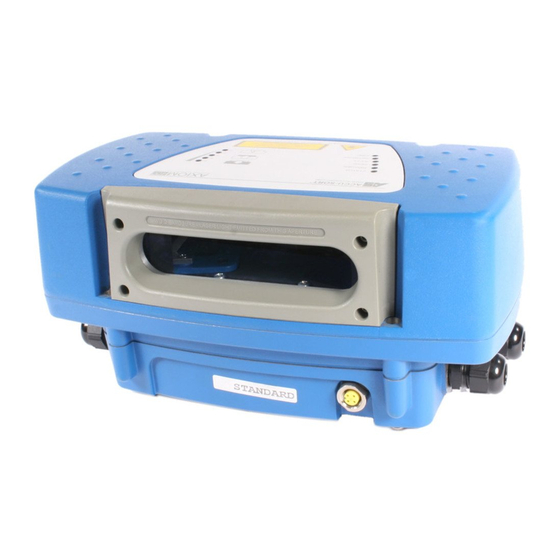
Every Axiom includes a universal wiring base and a plug-in scan head. The scan head is available in standard and high-density versions for high-speed scanning in fast moving applications. Figure 1-1: Accu-Sort Axiom with Wiring Base (bottom) and Scan Head (top) 01-AXIOM400-Introduction_R10.doc Accu-Sort Systems, inc. - Page 12 AXIOM™ 400 Product Manual Though technologically advanced, the Axiom is designed for easy setup and operation. Axcess Setup software for the Axiom line of Accu-Sort bar code readers, ® -based user interface. Using the Axcess Wizard or provides a familiar Windows the Axcess Explorer, you can configure your Axiom readers without the need for onsite service.
-
Page 13: The Axiom Scan Head
Axiom is reading bar codes. See Chapter 5, Setup and Operations. User self test mode helps in diagnostic mode. Used in conjunction with the signal strength LEDs, the self-test mode enables the user to quickly determine if one of the four lasers is faulty. 01-AXIOM400-Introduction_R10.doc Accu-Sort Systems, inc. - Page 14 20 different bar codes within a single “trigger.” If you want to check your understanding of basic bar code scanning concepts, go to the Accu-Sort Internet website at http://www.accusort.com/ to view our Bar Code Basics training course. DRX®...
-
Page 15: The Axiom Wiring Base
Axioms to a shared power source. These connections include LEDs to indicate power polarity or fault conditions. Power supplies are also available from Accu-Sort. When using Accu-Sort power supplies, each Axiom uses its own supply. Dedicated trigger input (1): This terminal block connects the contacts of a sensor that detects the presence of a package in the Axiom’s scanning... - Page 16 All power and communications with the scan head occurs through this connector. Threaded conduit openings (4): All permanent connections (i.e., power, trigger, tachometer, and communications) are made to the wiring base, using conduit or cable, through these openings. Accu-Sort Systems, inc. 01-AXIOM400-Introduction_R10.doc...
-
Page 17: Axcess™ Configuration Setup Software
Context sensitive help is available to assist with use of the software. Figure 1-2: Accu-Sort Axcess Setup Software All Axiom functions are selected from the standard menu bar, Axcess Explorer, or the Axcess Wizard, providing multiple access points for all setup parameters. -
Page 18: Axiom Bar Code Scanning Solutions
If you know which items are needed, contact Accu-Sort’s Customer Service Department (ask for the Spare Parts Coordinator) between 8 AM and 4:30PM (EST) Monday through Friday at 1-800-BAR-CODE (Fax: 215-723-1515). -
Page 19: Safety
Please follow the safety precautions and warnings found in this manual when installing, setting up, operating, maintaining, troubleshooting or replacing any Accu-Sort products, parts, or related equipment. Following these precautions will prevent personal injury or damage to the unit. Failure to follow these precautions may also void your warranty. -
Page 20: General Precautions
Save all packing material in case you have to transport your readers. § § Use steel or aluminum as a mounting structure. An Accu-Sort mounting structure is recommended for optimum system performance. § Check mounting hardware periodically for tightness and stability. -
Page 21: Compliance Requirements
Routinely check all power cords, plugs, wiring, and cable connections for § any signs of exposed wire or deteriorating insulation. If you notice any damage, make arrangements with service personnel to repair or replace the damaged item immediately. 02-AXIOM400-Safety_R10.doc Accu-Sort Systems, inc. -
Page 22: Electrical Grounding Requirements
Below are some keys to effectively control unnecessary ESD damage when working with ESD-sensitive devices: § Define an ESD protective area and work on the ESD-sensitive devices in this area only. § Define static sensitivity of devices to be handled in ESD protective area. Accu-Sort Systems, inc. 02-AXIOM400-Safety_R10.doc... -
Page 23: Laser Safety
Laser Safety The AXIOM 400 uses visible laser diodes and emits a “moving” red beam. Do not stare into the Axiom’s exit window at the laser light source. Avoid direct eye exposure. The laser light level does not constitute a health hazard, however staring at the laser light for prolonged periods could result in eye damage. -
Page 24: Safety Labels And Locations
Figure 2-2: Label Placement Axiom Scan Head Figure 2-3: Label Placement Axiom Wiring Base WARNING: The following is molded into the Axiom’s exit window frame: AVOID EXPOSURE – LASER LIGHT EMITTED FROM THIS APERTURE. (See Figure 2.1.) Accu-Sort Systems, inc. 02-AXIOM400-Safety_R10.doc... -
Page 25: Mechanical Installation
IMPORTANT: The Axiom packaging is designed to protect the unit(s) during shipment. Do not throw it away. Save all packing material in case you need to transport your unit(s). The scan head and wiring base are shipped in separate packages. 03-AXIOM400-Mechanical_Installation_R10.doc Accu-Sort Systems, inc. -
Page 26: Installation Sequence(S)
Mounting Bracket (XMB) to the frame. (UMB, XMB, and mounting frame options are available from Accu-Sort.) Mount the wiring base to the UMB, XMB, or frame. Mount the Accu-Sort power supply to the UMB or XMB (optional). Mount trigger (optional). (See page 3-14.) Mount tachometer (optional). (See page 3-15.) Mount I/O modules (optional). -
Page 27: What You Need To Know About Your Application
While it isn’t possible to cover all application configurations, the next several pages provide the basics you need to mechanically install your Axiom Bar Code Scanning Solution. If you need additional assistance, feel free to contact your sales representative or customer service. 03-AXIOM400-Mechanical_Installation_R10.doc Accu-Sort Systems, inc. -
Page 28: Orientation Considerations
Use the following diagram to determine the near/optimum/far read distances. These dimensions result in the overall depth of field your application requires. Figure 3-1: Determining Read Range Accu-Sort Systems, inc. 03-AXIOM400-Mechanical_Installation_R10.doc... -
Page 29: Bar Code Orientations
Bar Code Skew, Pitch and Tilt These angles affect bar code readability. Bar codes pitched or skewed up to 45 degrees are still readable. Although some skew may occur, it should not exceed 45 degrees. Figure 3-3: Bar Code Tilt, Pitch and Skew Illustrated 03-AXIOM400-Mechanical_Installation_R10.doc Accu-Sort Systems, inc. -
Page 30: Reader Positioning
Figure 3-4 represents the Axiom’s range of motion when the Universal Mounting Bracket (UMB, PN 0105307002) is used. Figure 3-4: Axiom’s Range of Motion with UMB Accu-Sort Systems, inc. 03-AXIOM400-Mechanical_Installation_R10.doc... -
Page 31: Dimensions And Clearances
However, ease-of-access should be considered when locating the mounting position. USEFUL TIP: For installation, maintenance and service reasons, approximately 8-12 inches of clearance is recommended. Figure 3-5: Axiom Dimensions – Top View 03-AXIOM400-Mechanical_Installation_R10.doc Accu-Sort Systems, inc. - Page 32 Mechanical Installation AXIOM™ 400 Product Manual Figure 3-6: Axiom Dimensions – Left Side View Figure 3-7: Axiom Dimensions – Front View Accu-Sort Systems, inc. 03-AXIOM400-Mechanical_Installation_R10.doc...
-
Page 33: General Mounting Guidelines
Reference the General Electrical Installation Guidelines in Chapter 4. It is important that you follow all safety precautions when installing, setting up, operating, maintaining, troubleshooting or replacing any Accu-Sort products, parts or related equipment. Reference Chapter 2, Safety. Attaching the Wiring Base... -
Page 34: Attaching The Universal Mounting Bracket (Umb)
Axiom in relation to scanning area can be made after wiring is completed. Figure 3-9: Attaching Wiring Base to Universal Mounting Bracket (UMB) Accu-Sort Systems, inc. 03-AXIOM400-Mechanical_Installation_R10.doc... -
Page 35: Attaching The Axiom Power Supply To Umb
UMB. 4. If the power supply/mounting plate assembly is properly positioned to the UMB, use the screw (located on the opposite edge of the mounting plate from the two tabs) to lock the assembly in place. 03-AXIOM400-Mechanical_Installation_R10.doc Accu-Sort Systems, inc. -
Page 36: Attaching The X-Pattern Mounting Bracket (Xmb)
3. Insert the screws through the XMB into the threaded holes on bottom of wiring base. 4. DO NOT over-tighten screws. 5. Reference drawing 17480 in Appendix D for wiring information. Accu-Sort Systems, inc. 03-AXIOM400-Mechanical_Installation_R10.doc... -
Page 37: Attaching The Axiom Power Supply To Xmb
2. DO NOT over-tighten screws that hold the power supply to the adapter mounting plate. 3. Attach the power supply/mounting plate assembly directly to the XMB. Fasten to the two tabs on the XMB as illustrated in Figure 3-13. 03-AXIOM400-Mechanical_Installation_R10.doc Accu-Sort Systems, inc. -
Page 38: Mounting The Trigger Photoeye
The trigger signal should remain active while the symbol is being scanned. This does NOT apply to tracking applications. Figure 3-14: Photoeye Mounting Diagram Accu-Sort Systems, inc. 03-AXIOM400-Mechanical_Installation_R10.doc... -
Page 39: Mounting The Tachometer
The extrusion mounting kit (1000020568) is the same as shown here, but also includes mounting hardware for attaching to Accu-Sort mounting structures. If you are not using the tachometer mounting kit, create a weight or spring assembly to put tension on the back of the tachometer, ensuring that the wheel makes strong contact with the conveyor. -
Page 40: Mounting The I/O Modules
4. Using a screwdriver, secure the I/O module by tightening the captive screw (that goes through the module) into the circuit board. DO NOT over- tighten screw. (See Figure 3-17, right photo.) Figure 3-17: Installing an I/O Module Accu-Sort Systems, inc. 03-AXIOM400-Mechanical_Installation_R10.doc... -
Page 41: Installing A Scan Head
3. Gently, press the scan head down until it firmly connects with the wiring base. Figure 3-18: Axiom Scan Head Installation on Wiring Base Wiring Base Connector Alignment Scan Head Connector Figure 3-19: Connecting Axiom Scan Head to the Wiring Base 03-AXIOM400-Mechanical_Installation_R10.doc Accu-Sort Systems, inc. - Page 42 Figure 3-20: Axiom Scan Head Alignment Pin Locations 4. Secure the scan head to the wiring base with the four captive screws. 5. Alternately tighten screws. DO NOT over-tighten screws. Figure 3-21: Axiom Scan Head Captive Screw Locations Accu-Sort Systems, inc. 03-AXIOM400-Mechanical_Installation_R10.doc...
-
Page 43: Electrical Installation
Review all installation-specific drawings. Review and plan the power requirements for your application. Review and plan the communications requirements for your application. Install the Axcess setup software on your PC. (Reference Axcess Software Manual. See Chapter 2, Getting Started.) 04-AXIOM400-Electrical_Installation_R10.doc Accu-Sort Systems, inc. -
Page 44: Installation Sequence(S)
(Reference drawings 107480 and 107481 in Appendix D.) Special instructions for functional set-up of a multi-reader network are provided in Chapter 5. Accu-Sort Systems, inc. 04-AXIOM400-Electrical_Installation_R10.doc... -
Page 45: General Electrical Installation Guidelines And Precautions
General Electrical Installation Guidelines and Precautions It is important that you follow these general precautions when installing, setting up, operating, maintaining, troubleshooting or replacing any Accu-Sort products, parts or related equipment. CAUTION: The Axiom uses Class 3R lasers IEC, (Class II CDRH). Avoid staring at the laser light source. -
Page 46: Wiring The Axiom
Wiring tables, printed on the wiring base insulation cover, help simplify installation. (See Figure 4-2.) Remember: Wire to the terminal blocks, left-to- right, coordinating your wiring with the table, top-to-bottom. Figure 4-2: Wiring Tables on Wiring Base Insulating Cover Accu-Sort Systems, inc. 04-AXIOM400-Electrical_Installation_R10.doc... - Page 47 Only use connectors designed for connecting to aluminum. Reference: UL 486B Wire Connectors for use with Aluminum Conductors, UL 486C Splicing Wire Connectors, and UL 486E Equipment Wiring Terminals for use with Aluminum and/or Copper Conductors 04-AXIOM400-Electrical_Installation_R10.doc Accu-Sort Systems, inc.
-
Page 48: Cable And Conduit Connections
Wiring bases are shipped with four (4) cord grips and three (3) hole plugs. Be sure to follow Accu-Sort’s wiring recommendations. (See Figure 4-1 and Table 4-1.) -
Page 49: Power Requirements
For PLUGGABLE EQUIPMENT (i.e., Axiom using AC power supply with non- detachable power cord), the socket-outlet must be installed near the equipment and must be easily accessible. 04-AXIOM400-Electrical_Installation_R10.doc Accu-Sort Systems, inc. -
Page 50: Power Supply Connections
Using Accu-Sort Power Supplies Single Reader The Axiom reader requires 30 watts (maximum) of power. Two Accu-Sort power supplies are available. These power supplies are IP65 rated for industrial environments. 120 VAC Power Supply (PN 0105365001) plugs directly into a standard wall electrical socket. - Page 51 LPS or Class 2 power supply. The supply must provide 30 watts (12-30 VDC) of power to each Axiom. Single Reader When a single reader application uses a non Accu-Sort supply, follow the INPUT POWER wiring table to assure proper wiring.
- Page 52 USEFUL TIP: In daisy-chained power applications, if the first or second unit’s and the last unit‘s LED is GREEN, you need to swap the Polarity LED is INPUT POWER wiring of the first unit with LED and the OUTPUT POWER wiring of the last unit with LED. Accu-Sort Systems, inc. 04-AXIOM400-Electrical_Installation_R10.doc...
-
Page 53: Trigger Connections
Figure 4-8: Wiring Trigger to Axiom Wiring Base Connect trigger wiring to the wiring base terminal blocks. (See Figure 4-8.) Wire the Accu-Sort photoeye as indicated in shaded area of Table 4-2. (Wire colors indicated for standard NPN Output, shown in shaded areas.) -
Page 54: Tachometer Connections
(See Figure 4-9.) Figure 4-9: Wiring Tachometer Input to Axiom Wiring Base When a tachometer is required, Accu-Sort tachometer (PN 1000019875) is recommended. Wire this tachometer as indicated in shaded area of Table 4-3. (Wire colors indicated for standard NPN Output, shown in shaded areas.) -
Page 55: Rs232/422 Communications Connections
COM / RS232 wiring table to assure proper wiring. IMPORTANT: Before attempting to use RS232 communications with RTS/CTS, contact Accu-Sort Customer Service for additional information. RS422 Connections Use RS422 for a direct connection to a controller, personal computer, or other device. -
Page 56: Ethernet Communications Connections
, Appendix A: Guide to Axiom Networking. Another useful source of information is the ODVA official web site (www.odva.org). USEFUL TIP: To simplify your network installation, Accu-Sort offers the following options: RJ45 adapter cables (10 and 20 ft. lengths) a 5-port Ethernet switch (Linksys) and an 8-port dual speed Ethernet switch (10/100). -
Page 57: I/O Module Connections
3 to 60 VDC 3 A max. * 1000056137 AC Output Module black 12 to 42 VAC 3 A max. * NOTE: Relay modules are only for connection to SELV, LPS power source. * Derate 33mA/deg above 25C. 04-AXIOM400-Electrical_Installation_R10.doc Accu-Sort Systems, inc. - Page 58 Input module 1000056135 is most often used for an END TRIGGER photoeye application. (Reference drawing 107482 in Appendix D for wiring details.) NOTE: Any other input module application requires custom software. Contact Accu-Sort Customer Service for more information. Accu-Sort Systems, inc. 04-AXIOM400-Electrical_Installation_R10.doc...
-
Page 59: Installing A Scan Head
Configure the Axiom’s parameters to meet the needs of your application. Axcess Setup Software Manual (See and online help for details.) first-time startup operations See Chapter 5 for details regarding and an checklist 04-AXIOM400-Electrical_Installation_R10.doc Accu-Sort Systems, inc. - Page 60 4-18 Electrical Installation AXIOM™ 400 Product Manual Notes: Accu-Sort Systems, inc. 04-AXIOM400-Electrical_Installation_R10.doc...
-
Page 61: Setup And Operations
Connection Mode: Setup Cable Reader Name: Axiom Control Panel Buttons Enabled Code 128 (10-30 characters) IP address 192.0.0.100 Perform the following setup procedure using these defaults or configure your Axiom with your application’s parameters using the Axcess Setup Software. 05-AXIOM400-Setup_and_Operations_R10.doc Accu-Sort Systems, inc. -
Page 62: First-Time Setup
Reference the Axcess for Axiom Setup Software Manual for further information. First-time Setup Procedure To setup your AXIOM 400 bar code reader: 1. Install Axcess on the PC you will use to setup your Axiom. 2. Connect the programming setup cable to the Axiom. -
Page 63: Operations Checklist
Adjust mounting as needed for optimal performance. Modify Axiom parameters as needed for optimal performance. Save parameters to scan head. Backup parameters from scan head to wiring base. (See Table 5-3.) Backup parameters to disk (optional, but recommended). 05-AXIOM400-Setup_and_Operations_R10.doc Accu-Sort Systems, inc. -
Page 64: Axiom Control Panel Indicators
(See Table 5-2.) Link This LED is LINK indicator for Ethernet. GREEN Flashes when connected to a network. Bar Graph Scan quality indicator. Also flashes whenever copying (LED 1 - 5) parameters to/from wiring base. Accu-Sort Systems, inc. 05-AXIOM400-Setup_and_Operations_R10.doc... - Page 65 Tools > Axiom Commands > Test Mode.) REMEMBER: Axiom’s control panel buttons can be enabled/disabled through the use of the Axcess setup software. (Reference Axcess Software Manual. See Modify > Axiom Configuration, Enable Axiom Control Panel Buttons.) 05-AXIOM400-Setup_and_Operations_R10.doc Accu-Sort Systems, inc.
-
Page 66: Checking Operations With Axcess
Client in the network. Each client is identified in the Read Rate Log by the unique name and IP address assigned to it using Axcess. Reference the Axcess Software Manual and online help for more information. Figure 5-3: Example Read Rate Log for Multi-Reader Network Accu-Sort Systems, inc. 05-AXIOM400-Setup_and_Operations_R10.doc... -
Page 67: Standalone Operation
PN 1000020569 PN 0104636001 (US) PN 0104636002 (Metric) Programming Cable PN 1000007308 Universal Mounting Bracket PN 0105307002 AC Power Power Supply PN 0105365001 (120V) PN 0105365002 (240V) Figure 5-5: Schematic Diagram of Typical Single-Unit Axiom Installation 05-AXIOM400-Setup_and_Operations_R10.doc Accu-Sort Systems, inc. -
Page 68: Tracking Operation
Setup Functions for Axiom Tracking Operation Modify > Tracking – Tachometer (define tach type) Modify > Tracking – Axiom Mounting Modify > Tracking – Transmit Modify > Tracking – Track Config Reference the Axcess Software Manual and online help for details. Accu-Sort Systems, inc. 05-AXIOM400-Setup_and_Operations_R10.doc... -
Page 69: X-Scanning Operation
Setup Functions for Axiom Clients Modify > Axiom Configuration - Reader Name (Client 1,2,3) Network Settings – IP address and Group # Reference the Axcess Software Manual and online help for details on setting up a multi-reader network. 05-AXIOM400-Setup_and_Operations_R10.doc Accu-Sort Systems, inc. -
Page 70: Multiple-Reader Network Operation
Setup Functions for Axiom Clients Modify > Axiom Configuration - Reader Name (Client 1,2,3) Network Settings – IP address and Group # Reference the Axcess Software Manual and online help for details on setting up a multi-reader network. Accu-Sort Systems, inc. 05-AXIOM400-Setup_and_Operations_R10.doc... -
Page 71: Scanning Array / Tunnel Operation
Network Settings - # of Client Readers, IP address, and Group # Setup Functions for Axiom Clients Modify > Axiom Configuration - Reader Name (Client 1,2,3,4,5) Network Settings – IP address and Group # Reference the Axcess Software Manual and online help for details. 05-AXIOM400-Setup_and_Operations_R10.doc Accu-Sort Systems, inc. - Page 72 5-12 Setup and Operations AXIOM™ 400 Product Manual Notes: Accu-Sort Systems, inc. 05-AXIOM400-Setup_and_Operations_R10.doc...
-
Page 73: Maintenance
For cleaning the Axiom’s exterior Cleaning solutions Mild detergent solution for cleaning the Axiom’s exterior. 70% denatured alcohol, 30% de-ionized water solution for cleaning exit window Soft cotton swabs Use to clean Axiom reader’s exit window or lint-free cloth 06-AXIOM400-Maintenance_R10.doc Accu-Sort Systems, inc. - Page 74 3. Carefully remove any debris in or around the exit window. 4. Wipe the exterior (except the exit window) with a clean, soft cloth dampened slightly with a mild detergent solution. 5. The exit window should be cleaned after this task is completed. Accu-Sort Systems, inc. 06-AXIOM400-Maintenance_R10.doc...
- Page 75 6. Apply the cleaning solution to the exit window. 7. Remove any streaks or remaining moisture from the exit window with a dry, soft, lint-free cloth or lens paper. 8. Verify Axiom reader operation. Follow the Operations Checklist procedure in Chapter 5. 06-AXIOM400-Maintenance_R10.doc Accu-Sort Systems, inc.
-
Page 76: Cleaning Trigger Photoeye
3. Clean the photoeye’s lens using the denatured alcohol solution and a cotton swab or lens paper. 4. Check the reflector on the opposite side of the transport. Clean as necessary. 5. Verify photoeye operation. Follow the procedure on page 6-7. Accu-Sort Systems, inc. 06-AXIOM400-Maintenance_R10.doc... - Page 77 3. Using a clean, soft cloth, wipe the wheels of the tachometer clean using a mild detergent solution. 4. Before restarting the system, be sure the tachometer is making good contact with the product transport. 5. Verify tachometer operation. Follow the procedure on page 6-7. 06-AXIOM400-Maintenance_R10.doc Accu-Sort Systems, inc.
-
Page 78: Tighten Mounting Hardware
(Reference Chapter 3, Installation.) 1. Check all wiring connections to the wiring base terminal blocks. Tighten as necessary. Do not over-tighten. Check all cabling/conduit for signs of wear/damage. Repair/replace any damaged cable connections as necessary. Accu-Sort Systems, inc. 06-AXIOM400-Maintenance_R10.doc... - Page 79 3. Verify the Belt Speed is accurate when the conveyor is running. Use Tach LED in Wiring Base 1. Remove the scan head from the wiring base. 2. Slowly spin the tachometer wheel while verifying the tach LED in the wiring base is flashing. 06-AXIOM400-Maintenance_R10.doc Accu-Sort Systems, inc.
- Page 80 Maintenance AXIOM™ 400 Product Manual Notes: Accu-Sort Systems, inc. 06-AXIOM400-Maintenance_R10.doc...
-
Page 81: Troubleshooting
“time out” after three minutes. Status Indicators The Axiom provides several status indicators that you can use to troubleshooting performance during operations. They are found at two locations: Axiom Control Panel Axcess Diagnostics > Axiom Monitor screen 07-AXIOM400-Troubleshooting_R10.doc Accu-Sort Systems, inc. - Page 82 Bar Graph Read quality indicator (5 = Good, 1 = Poor). (LED 1 – 5) 5 = 81-100% 4 = 61-80% 3 = 41-60% 2 = 21-40% 1 = 00-20% NOTE: Also flashes during parameter upload/backup. Accu-Sort Systems, inc. 07-AXIOM400-Troubleshooting_R10.doc...
- Page 83 NOTE: Keep in mind that the buttons on the Axiom’s control panel can be enabled/disabled through the use of the Axcess setup software. (For details, reference the Axcess Software Manual, Modify > Axiom Configuration in Chapter 4.) 07-AXIOM400-Troubleshooting_R10.doc Accu-Sort Systems, inc.
- Page 84 (See Verify Tachometer Operation procedure in Chapter 6.) Trigger On outside edge of circuit board, behind scan head connector. When the trigger photoeye is blocked, the Trigger LED will light GREEN. (See Verify Photoeye Operation procedure in Chapter 6.) Accu-Sort Systems, inc. 07-AXIOM400-Troubleshooting_R10.doc...
-
Page 85: Diagnostics
Right-click this area for clearing, starting, stopping and logging options. USEFUL TIP: If EtherNet/IP communications are being used, message monitoring for Net Host #1 is not available. Reference the Axcess Software Manual, Chapter 6. 07-AXIOM400-Troubleshooting_R10.doc Accu-Sort Systems, inc. - Page 86 Axcess Tools > Axiom Commands > Test Mode On.) Hold code in the scan line. Verify the Axiom is reading the code. Correct any tilt, pitch, or skew problems. Remedy bar code printing problems. Accu-Sort Systems, inc. 07-AXIOM400-Troubleshooting_R10.doc...
- Page 87 Cannot connect configuration PC running Axcess to the Axiom’s Ethernet port. Cause(s) Improperly configured Ethernet port on configuration PC Solution(s) 1. Verify network port configuration on PC. Port on PC must be configured for a static IP address. 07-AXIOM400-Troubleshooting_R10.doc Accu-Sort Systems, inc.
- Page 88 Troubleshooting AXIOM™ 400 Product Manual Notes: Accu-Sort Systems, inc. 07-AXIOM400-Troubleshooting_R10.doc...
-
Page 89: Service
Service 8 Service There are a limited number of field-replaceable components that are part of Axiom 400 Bar Code Scanning Solution . In most cases, it is recommended that the component be replaced with a matching recommended spare part (RSP). These field-replaceable units (FRUs) are:... -
Page 90: Replacing A Scan Head
(Reference Axcess Software Manual. See Chapter 4, Restore Axiom Parameters from Wiring Base.) Download a parameter set you have saved to disk directly through the Axiom Configuration Port Connector using Axcess and the setup cable. Accu-Sort Systems, inc. 08-AXIOM400-Service_R10.doc... -
Page 91: Replacing A Wiring Base
11. Install the scan head to wiring base. 12. Follow procedure in Chapter 5 to confirm operation. 13. Optional: Backup scan head parameters to wiring base. This assures the parameters are available if the scan head ever needs to be replaced. 08-AXIOM400-Service_R10.doc Accu-Sort Systems, inc. -
Page 92: Replacing An I/O Module
5. Install replacement I/O module to correct location on wiring base. (Reference the parts list in Appendix A.) 6. Secure I/O module to wiring base. 7. Install the scan head to wiring base. 8. Test operation of device connected to the I/O module. Accu-Sort Systems, inc. 08-AXIOM400-Service_R10.doc... -
Page 93: Replacing A Power Supply
5. Mount replacement power supply in same location as faulty unit. 6. Install replacement power supply wiring through correct conduit opening. 7. Connect wiring to INPUT POWER terminal blocks. 8. Confirm power polarity (LED in wiring base). 9. Install the scan head to wiring base. 08-AXIOM400-Service_R10.doc Accu-Sort Systems, inc. -
Page 94: Replacing A Trigger Photoeye
4. Mount replacement photoeye in same location as faulty photoeye. 5. Install replacement photoeye wiring through correct conduit opening. 6. Connect wiring to Trigger terminal blocks. 7. Confirm photoeye operation (LED in wiring base). 8. Install the scan head to wiring base. Accu-Sort Systems, inc. 08-AXIOM400-Service_R10.doc... -
Page 95: Replacing A Tachometer
4. Mount replacement tachometer in same location as faulty tachometer. 5. Install replacement tachometer wiring through correct conduit opening. 6. Connect wiring to TACH terminal blocks. 7. Confirm tachometer operation (LED in wiring base). 8. Install the scan head to wiring base. 08-AXIOM400-Service_R10.doc Accu-Sort Systems, inc. - Page 96 Service AXIOM™ 400 Product Manual Notes: Accu-Sort Systems, inc. 08-AXIOM400-Service_R10.doc...
-
Page 97: Technical Specifications
AXIOM™ 400 Product Manual Specifications A Specifications This appendix provides detailed specifications for the Axiom 400. It provides specific information on: Characteristics Options and Accessories Dimensions Certifications Technical Specifications Axiom 400 Characteristic Description Name/Part Number Visible Laser Bar Code Reader, Axiom 400 Reference options/part numbers on Options and Accessories table in this appendix. -
Page 98: Power Supplies For Axiom
< 40 W Connections Male IEC Compliance pending (See Compliance table in this appendix.) Note: Accu-Sort reserves the right to change product specifications without notice. Characteristic Description Name/Part Number Dual Axiom Power Supply for use with XMB (X-Pattern Mounting Bracket) Dimensions L 8.76”... -
Page 99: Options And Accessories
Blower Assembly (230 V) – Use in bottom read application to keep scan window clean 1000059400 AXIOM 400 Bar Code Reader Documentation CD 1000055015 AXIOM 400 Bar Code Reader Manual (bound hardcopy) 1000057488 Axcess Installation Software and Documentation CD 1000057289 Axcess Software Manual (bound hardcopy) A1-AXIOM400-Specifications_R10.doc... -
Page 100: Dimensions
Specifications AXIOM™ 400 Product Manual Dimensions Accu-Sort Systems, inc. A1-AXIOM400-Specifications_R10.doc... -
Page 101: Xmb Dimensions
AXIOM™ 400 Product Manual Specifications XMB Dimensions The following illustration provides additional dimensional references for applications that utilize the dual-Axiom X-Pattern Mounting Bracket (XMB, PN 0106226002) as part of the mounting structure. A1-AXIOM400-Specifications_R10.doc Accu-Sort Systems, inc. -
Page 102: Certifications
EN 61000-4-6:1996, "(EMC), Part 4 -Section 6 Immunity to conducted disturbances, induced by radio-frequencies IEC 61000-4-11: 1994, "(EMC), Part 4 -Section 11 Voltage dips, short interruptions & variations immunity IEC 61000-3-2 A14, 3/2000 and 61000-3-3: Harmonic current emissions Fluctuating and Steady State Harmonics) Accu-Sort Systems, inc. A1-AXIOM400-Specifications_R10.doc... -
Page 103: B Read Charts
B Read Charts AXIOM 400 Scan Rate Explained The AXIOM 400 scan head can be configured with either one or two modules. Each module has the option of having one or two lasers installed, but each module only ever has one mirror wheel and one receiving sensor. - Page 104 Read Charts AXIOM™ 400 Product Manual Accu-Sort Systems, inc. A2-AXIOM400-ReadCharts_R10.doc...
- Page 105 AXIOM™ 400 Product Manual Read Charts A2-AXIOM400-ReadCharts_R10.doc Accu-Sort Systems, inc.
- Page 106 Read Charts AXIOM™ 400 Product Manual Accu-Sort Systems, inc. A2-AXIOM400-ReadCharts_R10.doc...
- Page 107 AXIOM™ 400 Product Manual Read Charts A2-AXIOM400-ReadCharts_R10.doc Accu-Sort Systems, inc.
- Page 108 Read Charts AXIOM™ 400 Product Manual Notes: Accu-Sort Systems, inc. A2-AXIOM400-ReadCharts_R10.doc...
- Page 109 The contraction of binary digit, the smallest unit of information in the operator intervention. This is a prerequisite feature of linear bar code binary system; a one or zero condition. scanners employed in open systems. A3-AXIOM400-Glossary_R10.doc Accu-Sort Systems, inc.
- Page 110 The specific assignment of data characters to symbol characters. electronic radiation from laser devices. Accu-Sort is in compliance with the CDRH regulations. communications protocol The rules governing exchange of information between devices connected character together on the same communications line.
- Page 111 Original parameters as programmed by Accu-Sort at the factory. Axcess element can be used to review the default settings and modify them, when Dimensionally the narrowest width in a character – bar or space.
- Page 112 When a program sends a document to the printer, it is engaging Exchange of predetermined signals between two devices establishing a in I/O activity; when the program sorts a list of terms, it is engaging in computational activity. connection. Usually part of a communications protocol. Accu-Sort Systems, inc. A3-AXIOM400-Glossary_R10.doc...
- Page 113 Narrow Bar (NB)/Narrow Space (NS) memory address Smallest code element, bar or space, in the bar code symbol. Also known A specific location, usually expressed as a hexadecimal number, in the as the X dimension. computer’s RAM. A3-AXIOM400-Glossary_R10.doc Accu-Sort Systems, inc.
- Page 114 A data verification method in which each character must have an odd responsible for the safety regulations governing acceptable limitations on number of on bits. electronic radiation from laser devices. Accu-Sort is in compliance with the NCDRH regulations. omni-directional Orientation is unpredictable and can be ladder, picket fence, or any angle near distance in between.
- Page 115 A buffer used to hold data in order until it is used or transmitted. quiet zone The abbreviation for revolutions per minute. Required distance before the first bar and after the last bar of the code that must be free of marks or printing. A3-AXIOM400-Glossary_R10.doc Accu-Sort Systems, inc.
- Page 116 If, for example, a device receives a NAK during a data was even or odd. There are five different parity selections as shown below: transmission, it will not resend the data at the completion of the transmission. Accu-Sort Systems, inc. A3-AXIOM400-Glossary_R10.doc...
- Page 117 United States and Canada. In asynchronous transmission, the first bit or element in each character, normally a space, that prepares the receiving equipment for the reception and registration of the character. A3-AXIOM400-Glossary_R10.doc Accu-Sort Systems, inc.
- Page 118 Used to describe bar codes that are longer (from the first to last bar) than device to stop sending data. they are high (from the top to bottom of the bars). Uniloader Diagnostic feature of Axcess that is used to reload reader firmware. Accu-Sort Systems, inc. A3-AXIOM400-Glossary_R10.doc...
-
Page 119: D Interconnect Drawings
Interconnect Drawings D Interconnect Drawings AXIOM 400 Interconnect Drawings The interconnect drawings provided in this appendix are useful when wiring your AXIOM 400 for the following applications: Controller/Client with Tachometer (107480) Controller/Client/Client with Tachometer (107481) Start/End Trigger Photoeyes (107482) Stack Light with Internal Relays (107483) A4-AXIOM400-Interconnect_Drawings_R10.doc... - Page 120 Interconnect Drawings AXIOM™ 400 Product Manual Notes: Accu-Sort Systems, inc. A4-AXIOM400-Interconnect_Drawings_R10.doc...
- Page 121 1. TACHOMETER MUST BE CONFIGURED FOR NPN OPEN COLLECTOR OUTPUT. DATE 2. TO KEEP DRAWING SIMPLER, CABLE SHIELDS ARE NOT SHOWN. INITIAL DESIGN RAD/TCS 11.7.04 AXIOM 400 "X" BRACKET 110 WATT POWER SUPPLY AXIOM 400 AXIOM 400 CLIENT CONTROLLER I/01+...
- Page 122 Interconnect Drawings AXIOM™ 400 Product Manual Notes: Accu-Sort Systems, inc. A4-AXIOM400-Interconnect_Drawings_R10.doc...
- Page 123 INDIVIDUAL AXIOM SCANNERS IN READ STATION. INCH [METRIC] ANGULAR MECH ENG IT MAY NOT BE DISCLOSED, COPIED, DEPT. [X±2.500] CONTROLLER/CLIENT/CLIENT W/TACH, AXIOM 400 ALL 3 SCANNERS COULD BE MONITORED BY OPENING .X±.1000 X±1.00° OR REPRODUCED, EXCEPT FOR THE .XX±.0200 [.X±0.500] .X±0.10°...
- Page 124 Interconnect Drawings AXIOM™ 400 Product Manual Notes: Accu-Sort Systems, inc. A4-AXIOM400-Interconnect_Drawings_R10.doc...
- Page 125 INCH [METRIC] ANGULAR AXIOM WILL TRANSMIT DATA TO SORTATION CONTROLLER. MECH ENG IT MAY NOT BE DISCLOSED, COPIED, DEPT. [X±2.500] START/END TRIGGER PHOTOEYES,AXIOM 400 .X±.1000 X±1.00° OR REPRODUCED, EXCEPT FOR THE AXIOM SCANNERS ARE CONFIGURED BY ATTACHING .XX±.0200 [.X±0.500] .X±0.10°...
- Page 126 Interconnect Drawings AXIOM™ 400 Product Manual Notes: Accu-Sort Systems, inc. A4-AXIOM400-Interconnect_Drawings_R10.doc...
- Page 127 AXIOM WILL TRANSMIT DATA TO SORTATION CONTROLLER. INCH [METRIC] ANGULAR MECH ENG IT MAY NOT BE DISCLOSED, COPIED, DEPT. [X±2.500] STACK LAMP W/INTERNAL RELAYS,AXIOM 400 AXIOM SCANNERS ARE CONFIGURED BY ATTACHING .X±.1000 X±1.00° OR REPRODUCED, EXCEPT FOR THE .XX±.0200 [.X±0.500] .X±0.10°...
- Page 128 D-10 Interconnect Drawings AXIOM™ 400 Product Manual Notes: Accu-Sort Systems, inc. A4-AXIOM400-Interconnect_Drawings_R10.doc...
- Page 129 No Read message................7-7 orientation ..................3-5 poor read rates................... 7-7 default parameters.................. 5-1 quiet zone ................... 3-6 Diagnostics Read LED ..................5-4, 7-2 Axiom Monitor..............5-3, 5-6, 7-5 read rate, check with LogViewer........... 5-6 Diverters....................3-16 Accu-Sort Systems, inc. IN-AXIOM400-Index_10.doc...
- Page 130 ....3-2, 4-2, 7-3, 7-5 recommendations ................2-2 installing multiple readers.............. 4-2 sequence recommended........3-2, 4-2, 7-3, 7-5 National Electrical Code..............2-3 Internet website, Accu-Sort’s .............. 1-4 noise, reduce or minimize............... 4-3 polarity check...................4-10 polarity check LED ................7-4 Laser safety protective earth ground ..............
- Page 131 Setup port, programming cable..........1-6, 1-7 120 VAC....................4-8 Skew, bar code ..................3-5 240 VAC....................4-8 Spare Parts Coordinator ................ 1-8 connections, Accu-Sort supplies........... 4-8 Startup disconnect device, readily accessible........4-8, 4-9 first-time..................... 5-1 mounting to UMB ................3-11 setup, first-time ................5-2 mounting to XMB ................3-13...
- Page 132 XMB..........3-13 mounting wiring bases to XMB........... 3-12 XMB dimensions................A-5 Warranty................... 3-1, 4-1 dual Axiom application ..............5-9 Wiring Multiple readers ................5-9 Axiom wiring base ................4-4 cable and conduit connections ............. 4-6 Accu-Sort Systems, inc. IN-AXIOM400-Index_10.doc...
Need help?
Do you have a question about the AXIOM 400 and is the answer not in the manual?
Questions and answers