Table of Contents
Advertisement
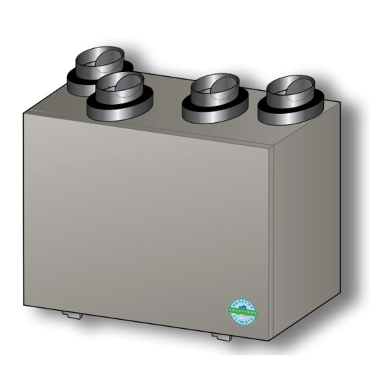
INSTALLATION INSTRUCTIONS AND HOMEOWNER GUIDE FOR HEALTHY CLIMATE
HEAT RECOVERY VENTILATOR (HRV) AND ENERGY RECOVERY VENTILATOR (ERV)
HRV5-150
HRV3-195, -300
Certain models have earned the E
efficiency guidelines set by Natural Resources Canada and the US EPA.
These models meet ENERGY STAR requirements only when used in Canada.
THIS MANUAL MUST BE LEFT WITH THE OWNER
FOR FUTURE REFERENCE
WARNING
Improper installation, adjustment, alteration, ser vice or
maintenance can cause property damage, personal injury
or loss of life.
Installation and service must be performed by a li censed
professional HVAC installer (or equivalent) or a service
agency.
CAUTION
As with any mechanical equipment, contact with sharp
sheet metal edges can result in personal injury. Take
care while handling this equipment and wear gloves and
protective clothing.
INDOOR AIR QUALITY
KIT AND ACCESSORIES
507363-02
1/2017
Supersedes 507363-01
HRV3-150-TPD/TPF, HRV5-200-TPD
HRV3-195, -300
HRV AND ERV VENTILATORS
S
mark by meeting strict energy
®
nErgy
tar
Shipping and Packing List
Package 1 of 1 contains:
1 - Assembled ventilator
1 - Bag assembly containing:
2 - Drain spout assemblies (HRV units only)
1 - Drain tee (HRV units only)
4 - Hanging straps
1 - Installation instruction
1 - Warranty
1 - Wall-mounted remote control
General Information
This instruction is intended as a general guide and does not
supersede local codes in any way. Consult authorities who
have jurisdiction before installation.
HEALTHY CLIMATE
ERV3-150, -200
HRV3-095
®
®
Advertisement
Table of Contents


Need help?
Do you have a question about the HRV Series and is the answer not in the manual?
Questions and answers