Advertisement
Quick Links
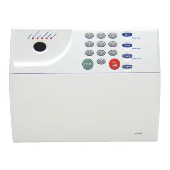
LS5000
Contents
Section 1 – Overview of System
Section 2 – Planning your Installation
Section 3 – Installing your System
Section 4 – Using the System
Section 5 – Programming the System
Section 6 – Engineer Programming
Section 7 – Maintenance
Section 8 – Extending the System
Section 9 – Radio Interference
Section 10 – Troubleshooting Guide
Section 11 – Summary Tables
Section 12 – Specifications
Section 1 – Overview of System
LS5000 high security alarm system is based on
cordless radio technology to give exceptional
levels of protection and reliability. It has the
ability to control up to 32 zones and can use both
cordless and wired detectors.
IMPORTANT – please read through Sections 1
- 4 before commencing installation. You will
find installation easier if you follow the steps in
the sequence shown.
1.1 Kit Contents
The system comprises:
Control Unit
This is the heart of the system. It receives signals
from detectors. Accepts inputs from a user and
activates warning devices such as siren and
strobe lights. The Control Unit must be wired to
a mains supply and to the external siren unit.
Wireless Passive Infra-Red Detector
The Passive Infra-Red Detector (PIR) senses the
body heat of a moving person. One unit can
cover an entire room (wire-free).
Wireless Magnetic Contact
Uses a magnetically operated switch to sense the
opening of the door or window.
Wireless Remote Control Key
Used for full arming, part arming or disarming
the system. In addition it is used for the panic
function.
Two-Wire Passive Infra Red Detector
The Passive Infra-Red Detector (PIR) senses the
body heat of a moving person. One unit can
cover an entire room. This detector only needs 2
non-polarity wires to connect to the two-wire
detector zone [=1 to =4]. Wired detector does not
rely on RF signal and hence cannot be jammed.
To complete your installation, you will also
require: (to be purchased separately)
1m flexible mains cable (3 core)
rechargeable Battery
fused connection unit (fused spur) plus
suitable cable clops and trunking
external Siren/Strobe Unit
6-core cable for connection of the Control
Unit to the external siren
Page 1
Ver:2.0
Advertisement

Related Manuals for Lynteck LS5000

Summary of Contents for Lynteck LS5000
- Page 1 Section 1 – Overview of System LS5000 LS5000 high security alarm system is based on cordless radio technology to give exceptional Contents levels of protection and reliability. It has the ability to control up to 32 zones and can use both cordless and wired detectors.
- Page 2 Pencil & bradawl Wire cutters & wire stripper Ladder or other safe working platform Eye protection 1.3 System Features CONTROL UNIT Detector Learning System – every LS5000 cordless detector contains unique identification code; during installation the Control Unit will learn which detectors...
- Page 3 The Zone Omit (part set) facility allows wired to the Control Unit. you to have certain zones disabled when Reception of radio signals can be affected the system is armed; for example, at night by the presence of metal objects within a the system can be set with any upstairs few feet of the Control Unit, for example detectors omitted but the downstairs...
- Page 4 for the best general coverage in an average positioned to protect the front door. room. The detector has been designed to avoid false alarms, nevertheless, it is best to The example follows the guidelines as stated for avoid sitting the unit where it is looking each individual component, but there are directly at sources of heat such as fires and situations where additional accessories may be...
- Page 5 Section 3 – Installing your System 3.1 Control Unit Illustration 1 a) Connecting to mains power supply WARNING: Isolate the supply before starting work. All connections to the mains should be made in accordance with all the relevant wiring regulations, including correct fusing and isolation. If you are in any doubt, consult a qualified electrician.
- Page 6 WARNING: The Control Unit must never be operated from the mains with the front cover open. The user code is factory set to and is the same for every LS5000 system. If the system sounds during the installation pressing the factory set code of...
- Page 7 3.4 Checking the Location of the Wireless Detector The LS5000 alarm system uses advanced radio technology which under most circumstances will give more than sufficient transmission range. Before fitting the detectors, however, it is recommended that each wireless detector be tested in its final location to ensure that the control unit receives the radio signals transmitted by the detector.
- Page 8 b) Press on the control unit, now you are in walk-test mode. c) If the wireless detector is triggered, a signal will be transmitted and the LED goes on. (For the wireless PIR, during the first 15 minutes (approx.), the PIR detector will not trigger the tamper alarm.) d) Trigger the alarm in the detector, it will sound beep and indicate on the display the zone...
- Page 9 iii. If there is insufficient room to mount the detector on the frame then it can be fixed to the door or window instead, with the magnet fixed to the frame alongside it. For reliable operation, the front face of the magnet should be no more than 10mm below the front face of the detector – in some cases it may be necessary to place packing behind the magnet or detector to achieve this.
- Page 10 iii. If you are fitting the PIR in a corner, use mounting points ”A”, if you are fitting the detector on to a flat surface use mounting points “B” – the mounting points are shown by indentations in the plastic molding. Use a small drill to create two fixing holes at the mounting points (Illustration 11).
- Page 11 d. Open the door or window to which the door/window contact detector is fitted, the LED on the door/window contact should light for two seconds. The Control Unit will give a two-tone beep and the display will change to indicate the door/window contact detector zone number. Close the door. e.
- Page 12 3.11 Siren/Strobe Unit (to be purchased separately) Fit the external siren as detailed in its own installation manual, but wire it as detailed below CONTROL UNIT SIREN UNIT STB TRIGGER───────────── - STB BELL TRIGGER───────────── - TG BELL TAMPER (left) ─────── RETURN + AUX────────────────...
- Page 13 3.14 Installing Two-wired PIR (For extension also available to purchase separately as an accessory) i. Remove and retain the screw from the bottom of the PIR and lift off the cover. ii. Carefully remove the electronic module from its retaining clips, ensuring not to touch the pyroelectric sensor (Illustration 13).
- Page 14 x. In the Control Unit, against each of the two PIR connection terminals (zone =1, =2, =3 or zone =4), there is a 3-position (0,1,2) slide switch. These switches are factory pre-set at position “0” when no PIR is connected. When connecting one piece 2-wire PIR to the zone, you need to set the corresponding switch to position “1”.
- Page 15 If required, select the PIR LED “ON” or “OFF” option and the sensitivity (pulse count) by setting the corresponding jumpers on the electronic module. Note that Pulse 1 option is more sensitive than the pulse 4 option. Pulse 1 option is used when it is necessary to activate an alarm on the first detected pulse, or in high security installations –...
- Page 16 3.16 Installing Wired Door/Window Contact Detector (available separately as an accessory) i. Choose the location for each magnetic contact (remembering the need to wire them back to the Control Unit). Each contact consists of a magnetically operated switch (with screw terminals at the back) and a magnet in an identical housing.
- Page 17 Wiring Diagram 1 – Two-Wire PIR Connection Diagram Two non polarity CABLE flat wires CABLE Page 17...
- Page 18 Wiring Diagram 2 - Wired Movement Detector (PIR) Wiring Diagram Page 18...
- Page 19 Wiring Diagram 3 Connect to 12V Rechargeable battery Connect to the ‘power’ terminal of wired PIR or 14V AC external siren/strobe unit Connect to transformed 14V AC L: Connect to mains power live terminal L brown G green/yellow N blue N: Connect to mains power neutral terminal G: Connect to mains power ground terminal BELL TEMP...
- Page 20 Section 4 – Using the System 4.1 Changing the User Pincode The user code is factory set to and is the same for every LS5000 system. It is recommended that the user code be changed immediately after completing the basic installation.
- Page 21 children. This code can only arm and disarm the system. 4.3 Arming the System Before attempting to arm the system, check that all doors and windows (particularly those fitted with a door/window contact detector) are securely closed and that all PIR detectors have an unobstructed view of the areas they cover.
- Page 22 4.5 Arming the System with zones omitted (part setting) Proceed as follows. Enter: Press User code display changes to flashing. Secondary Code Partial Arm 1 Omit Partial Arm 2 Display changes to Partial Arm 1, Partial Arm P2 or Partial Arm P3 accordingly. Store Partial Arm 3 Display...
- Page 23 4.8 Changing in Cordless Detector Batteries Every LS5000 cordless detector will detect when its batteries are in need of replacement. When this occurs, a “low battery” transmission is sent to the control unit and a low beep will be sounded when the detector is triggered.
- Page 24 4.9 Wireless Detector Transmissions To comply with advance wireless security system standard , the wireless detectors in your LS5000 alarm system must transmit several kinds of signal. In addition to normal Alarm and Tamper transmissions, the detectors also send: Supervisory signals –...
- Page 25 Section 5 – Programming the System Your LS5000 System incorporates many programmable functions which can be used to make your installation more flexible to your needs. Some of the functions can be activated by the user code while others can be activated by engineer code.
- Page 26 Enter new Siren Duration Time, New siren duration in minutes – only values between 01 to 20 are allowed. The time entered will be displayed. (N.B. You must always enter two digits). If an invalid time is entered, the control unit gives an error beep and the display reverts to for you to enter another value.
- Page 27 Press ,display shows and siren sound (internal and external). Press ,Siren stop sounding (or wait for 30 seconds for automatic stop). RESET b) To test the strobe, press keys as follows: Press ,display changes to flashing. Press ,display changes to Program Press ,display shows...
- Page 28 The factory default engineer code is 6.1 Setting new Engineer Code The engineer code is factory set to and is the same for every LS5000 system. It is recommended that the engineer code be changed immediately after completing the basic installation.
- Page 29 6.3 Setting Entry/Exit Zones As mentioned earlier, zones are factory set to be entry/exit zones. But, in addition to these zones, you can program other zones also to be entry/exit zones. To do so, proceed as follows: Press ,display changes to flashing.
- Page 30 Because of this pincode is factory default to 5-6-7-8 in every LS5000 system and it is an option to use. You should notify the system of your will to activate it. If you do this, you should immediately change the secondary pincode (refer section 4.2), this ensures that the system does not contain a “global”...
- Page 31 6.8 Enable/disable supervisory detection When this function is enabled (factory default OFF), a supervisory signal will automatically send every one hour, allowing the Control Unit to monitor the status of a detector (For more information, please read section 4, 4.9). To do so, proceed as follows: Press ,display changes to...
- Page 32 6.10 Reset all Functions Like the reset jumper, this function allows you to delete the control unit memory. While the reset jumper retrieves the control unit to its factory defaults, this function does not delete any detector and/or accessory that was already learned by the system. Press ,display changes to flashing.
- Page 33 Section 8 – Extending the System front cover (after disconnecting the mains) and moving the push on link marked “INTERFERENCE” on the circuit board A number of accessories are available to from ON to OFF. extend your system to suit your exact requirements.
- Page 34 Section 10 – Troubleshooting Guide Symptoms Possible causes and cures 1) Control Unit Display blank, Mains LED off – unit totally No power supply to unit. “dead”. Check connectors to mains and rechargeable battery. Check control unit fuses F-AC & F-AUX. Display blank, Mains LED flashing.
- Page 35 Section 11 – Summary Tables GENERAL USER-PINCODE FUNCTIONS SUMMARY Function Press Procedure Full Set User or Secondary Pincode X-X-X-X Press Full Full Part Set User or Secondary Pincode X-X-X-X Press P1, P2 or P3 P1, P2 or P3 Unset User or Secondary Pincode X-X-X-X Omit zones User Pincode...
- Page 36 Section 12 – Specifications Control Unit Type Microprocessor based wireless/wired hybrid control panel Housing Polycarbonate Zones 24 alarm zones (16 wireless, 8 wired) Entry/Exit Delay 10-60 seconds programmable Siren Duration 1 – 20 minutes programmable Classification System conforms to equipment requirements of BS6799 class 3 Radio System 433MHz transmitter.
Need help?
Do you have a question about the LS5000 and is the answer not in the manual?
Questions and answers