
Related Manuals for Lynteck LS800S

Summary of Contents for Lynteck LS800S
-
Page 1: Table Of Contents
LS800S Intruder Alarm System Engineering Manual Table of Contents Section 1 – Overview of System Kit Contents Tools Required System Features Section 2 – Planning your installation Location of components Planning the location for the system components Section 3 – Installation your system... -
Page 2: Section 1 - Overview Of System
SECTION 1 – OVERVIEW OF SYSTEM The LS800S system is an indoor alarm system based on our patented two-wire technology to give exceptional levels of protection and reliability. It is a fuseless system with special electronic design for short-circuit protection. It is simple to use, easy to install, no special tools or training is required. -
Page 3: Tools Required
1.2 Tools Required The following tools are required for installation: ★ Large & small flat bladed screwdrivers and cross point screwdrivers ★ Hammer ★ Power drill ★ Wire cutters and wire stripper ★ Eye protection (recommended when using a power drill or hammer) 1.3 System Features ★... -
Page 4: Section 2 - Planning Your Installation
SECTION 2 – PLANNING YOUR INSTALLATION 2.1 Location of components Control Unit – Location In choosing a suitable location you should bear in mind: ★ The user needs to reach the Control Unit or Remote Key Reader easily within the allocated time, when entering and leaving the premises. - Page 5 Door/Window Contact Detectors – Location ★ Door / Window Contact Detector is designed to detect a door or window opening, so it is better mounted onto the frame with a magnet mounted next to it on the door or window. ★...
-
Page 6: Planning The Location For The System Components
Dining room Kitchen Bedroom #1 Bedroom #2,#3 DI NI NG RO O M ( ZO NE1) ( ZO NE5) LS800S LS800S CO NTRO L UNI T CONTROL UNIT KI TCHEN LI VI NG RO O M ( ZO NE2) Ground Floor... - Page 7 Hall Spare Kitchen Bedroom#1 Bedroom#2 ( ZO NE1) REM O TE READER ( ZO NE4) HALL LS800S CO NTROL UNI T BEDRO O M BEDRO O M BELLBO X KI TCHEN ( ZO NE2) ( ZO NE8) ( ZO NE7) ( ZO NE6) The Zone 4 PIR has been placed in the Dining/Living room to protect this general area.
- Page 8 SECTION 3 – INSTALLING YOUR SYSTEM 3.1 Control Unit Remove and retain the two holding screws from the bottom of the front cover and carefully hinge off the front cover of the control unit. Mark and drill holes for the three mounting screws. Put in the wall plugs and have a mounting screw on the top (hanging screw) inserted.
- Page 9 Control Unit. DO NOT plug in the power plug to the main supply until all connections are completed and all units properly mounted and front cover of the Control Unit is closed and secured. WARNING: All connection to the mains should be made in accordance with all relevant wiring regulations.
- Page 10 NOTE 1: For connecting magnetic contacts to any of Zone 1-3, (For more information please refer Illustration 10). NOTE 2: Illustration 3 show one piece of 2-wire PIR detector is connected to each of Zone 4 to Zone 7; and therefore the PIR zone slide switches opposite the PIR zone terminals are put in position 1.
-
Page 11: Movement Detector/Pir
3.2 Movement Detector/PIR ★ Remove and retain the screw from the bottom of the PIR and lift off the cover. ★ Carefully remove the electronic module from its retaining clips, ensuring not to touch the pyroelectric sensor (Illustration 4). Illustration 5 Illustration 4 ★... - Page 12 Connect the 2 wires to the PIR, polarity is not important. ★ Run the cable back to the Control Unit, fixing the cable with cable clips and enter the wire ★ into the back of the Control Unit through any convenient cable hole. Connect to one of the two wire PIR zone (zone 4 to zone 8) terminals in the Control Unit as ★...
-
Page 13: Door/Window Detector
3.3 Door/Window Contact Detector Choose the location for each magnetic contact (remembering the need to wire them back to ★ the Control Unit). Each contact consists of a magnetically-operated switch (with screw terminals at the back) and a magnet in an identical housing. The switch (the part with screw terminals and cable) should be mounted on the frame. -
Page 14: Remote Key Reader
3.4 Infra Red Remote Reader Remove the cover retaining screws from the top and the bottom of the Reader cover ★ (Illustration 11). Take off the cover from the reader baseplate. Pow er Par t / Hol d Fixing holes TWO WIRE SYSTEM Illustration 12 Illustration 11... -
Page 15: Testing The System
4. The tests are performed consecutively. Advance to next test automatically after 3 seconds Low volume sounder on LS800S control panel High volume sounder on LS800S control panel and strobe External bell and strobe Set terminal +ve output and strobe On completion of walk test, close the cover of the control unit and an ‘OK’... -
Page 16: Section 4 - Using Your System
N.B. Remote keys provided are factory pre-learnt. Learning procedure is not necessary. 4.2 Learn the first remote keys When all the remote keys are lost or not recognized by the LS800S system, you may need to re-learn all remote keys into the system. The control panel will remove all registered keys previously learned. -
Page 17: Select Entry Timer
4.3 Select Entry Timer The entry timer jumper on the control panel (See Illustration 3) is set to 30 seconds (default setting) which allows user to enter the premises and unset the system within 30 seconds. User may put the entry timer jumper on the control panel to 15 seconds which allows user to enter the premises and unset the system within 15 seconds. -
Page 18: Status Of Led Indications
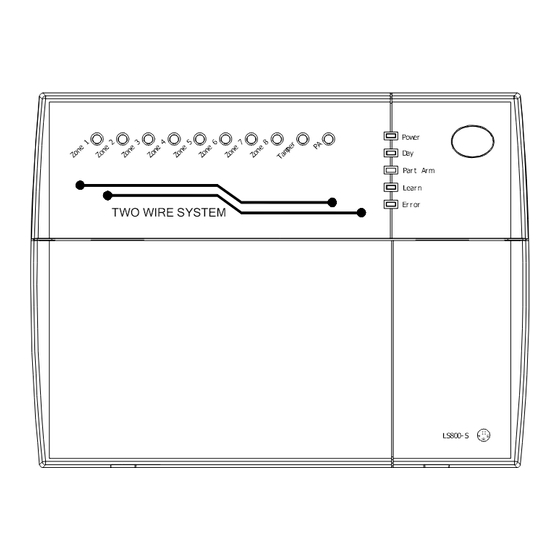
4.6 Status of LED indications: STATUS LED INDICATIONS “Power” LED On A/C power in use “Power” LED flashing Back-up battery in use. “Day” LED illuminated System “disarmed” (unset), ready to accept User commands by remote key. “Day” LED Off System armed (set). With “Part Arm”... -
Page 19: Section 5 - Maintenance
SECTION 5 – MAINTENANCE Once every three months, ★ Test all detectors. ★ Check loudspeaker of control unit. ★ Test sirens and strobes of the bellbox. Additionally, once every year, ★ Replace the batteries of the remote keys Additionally, once every three years, Replace the rechargeable battery in the Control Unit. -
Page 20: Section 7 - Specifications
SECTION 7 – SPECIFICATIONS Control Unit Type Microprocessor based control unit with patented two-wire technology Housing Polycarbonate Zones 8 Alarm Zones (3 Intruder zone; 5 Patented two wire Intruder zone) Exit Delay 30 seconds Entry Delay 15 or 30 seconds selectable Siren Duration 20 minutes Remote keys...
Need help?
Do you have a question about the LS800S and is the answer not in the manual?
Questions and answers