
Related Manuals for G-MORE ORANGERY Series

Summary of Contents for G-MORE ORANGERY Series
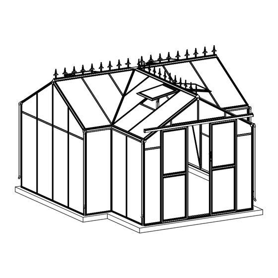
- Page 1 ORANGERY GREENHOUSE Assembly Instructions www.ttshop.se MODEL:GM34606 PRODUCT SIZE(LxWxH):381x377x250cm PLEASE READ CAREFULLY BEFORE ASSEMBLY...
- Page 2 CONTENTS 1. Assembly Advice ..............Page 1 2. Product Features ..............Page 1 - 3 3. Parts List ................Page 4 - 7 4. Overview of Front Wall ............Page 8 Overview of Rear Wall ............Page 9 Overview of Sides and Roof ..........Page 10 - 11 Overview of Roof Vents ............Page 12 Overview of Doors ..............Page 13 5.
- Page 3 Assembly and Maintenance Advice 1. For safety purposes, we strongly recommend that this product is assembled by at least two people. 2. Some components have sharp metal edges. Please be careful when handling metal components. Please wear gloves, shoes and safety goggles during assembly. 3.
- Page 4 3. Base anchor brackets are included as standard with expanding bolts to ensure a secure fixing into concrete or paving. Alternatively, you can use the brackets to fix into a timber base with wood screws (not provided). Expansion bolt Steel pegs in soil in concrete 4.
- Page 5 7. Remove approximately 2 inches of film from all sheet edges before installing and remove all film immediately after the construction is completed. Please ensure that the side with the white film faces outwards. 8. Decorative crestings are available as an optional extra. Each 2’ wide glazing panel in the sides and roof requires one set.
- Page 6 GM34606 (ALU. Box No. 1) Rear Wall Assembly x 2pcs Front Assembly PART PART L01A L01A L01B L01B L01C L01C L01D L01D L02C L03C L03E L03D L03F L03G L04A L04A L05A L05A L05B L11A L08C L11B L11A L11D L11B L11E L11C L12C L12C...
- Page 7 GM34606 (ALU. Box No. 2) 6 x 6 Section Assembly PART PART L06C L22B L06D L22C L06E L07A L07B L07C L07D L07E L08B L08D L08E L08F L08G L02A L02B L02D L02E L02F L02G L03A L03B L04A L05C L05D L05E L05F...
- Page 8 GM34506-T (ALU. Box No. 3) Door Assembly Parts Parts Roof Vents Assembly x 4pcs PART PART PART PART L15A L16A L19A L16B M8X60 L19B M6X20 L18A M6X10 L18B L21A L18C L21B J02R/L M8X30 L18D J03R/L L21C Ø4X14 L21D Ø4X14D Ø4X10 6x6 Section Ø4X40 PART...
- Page 9 GM34606 (PC Box No. 1) PART PART PC/Glass N0.1 阳光板部分 玻璃部分...
- Page 10 PART PART PART L01A L01B L01C J02R/L L01D L02C L03E L03F L04A Front Wall Assembly L05A Overview L11A M8X60 L11B M6X10 L11D L11E Ø4X14 L12C Ø4X14D L12D L12F L12G Main Frames Panels L01C Aluminium Capping L02C L01D L11B L04A L11A J02R L12F L05A...
- Page 11 PART PART PART L01A L01B L01C J02R/L L01D L03C L03D Rear Wall Assembly x2pcs L03G L04A Overview L05A L05B L08C M8X60 L11A M6X10 L11B L11C Ø4X14 L12C Ø4X14D L12D L12E L12G Main Frames Panels L01C Aluminium Capping L01D L11B L03G L11A J02R L04A...
- Page 12 PART PART PART PART L06C L22B L06D L22C L06E L11A L07A L11C L07B L11F L07C L07D L11G L07E L11H L12A L08B L12B L08D L12G L08E M8X60 L12H L08F M6X20 L12I L08G M6X10 L12J L09A L12K L09B Ø4X14 L09C Ø5X25 L09D L09E L02A L02B...
- Page 13 L12Gx4pcs L12Kx2pcs L12Bx5pcs L09A L12Ix2pcs L12Jx2pcs L09A L12Hx2pcs L12Ax5pcs L09C L09D L09B L11Ax4pcs L09E L11Cx6pcs L11Hx4pcs L11Cx2pcs L06E L02E L02B L02G L03A L02F L22x11pcs L22C L02B L02D L05Dx8pcs L06D L22BX2PCS L07Ax2pcs L07C L05E L06C L04Ax4pcs L07D L07B L22B L05C L07E L05C L03A L05F...
- Page 14 PART PART PART L15A L19A Ø4X14 L19B Ø4X14D Roof Vent Assembly Ø4X10 Overview of Roof Vents L21A L21B L15A L19A L19A L21B L21A L21A L19B L21B...
- Page 15 PART PART PART L16A L16B J03R/L M8X30 Door Assembly L18A L18B Ø4X14 Overview L18C Ø4X14D L18D Ø4X40 L21C L21D W03R L18D W03L L18D L16A L16A L16B L16B L18A L18C L18B L16A L16A L21C L16A L21C L16A L21D L21D L18A L16B L16B L16A L16A...
- Page 16 PART PART PART L15A L19A Ø4X14 L19B Ø4X14D Ø4X10 L21A Roof Vent Assembly L21B L15A L19A L19A L21B L21A L21A L19B L21B...
- Page 17 L19A L19A L19B After connector B has been fitted, use the hole in the profile to tighten the connector in place. L19A L19B L19A Push down the button on connector B before inserting it into the end of the frame profile.
- Page 18 L21B L21A L21A L21B L21A/L21B First the polycarbonate glazing panel Y10 should be loosely retained by the bar capping profiles L21A and L21B. Next tap the bar capping gently into position with a rubber mallet, then fix the bar capping securely with Z01 screws.
- Page 19 Install the Z02 screws to prevent the L15A from sliding off the vent. L15A L15A Fix the W06 vent handles using Z03 screws. If required, automatic vent openers can be installed once the greenhouse is complete.
- Page 20 PART PART PART L16A L16B J03R/L M8X30 L18A Door Assembly L18B Ø4X14 L18C Ø4X14D L18D Ø4X40 L21C L21D W03R L18D W03L L18D L16A L16A L16B L16B L18A L18C L18B L16A L16A L21C L16A L21C L16A L21D L21D L18A L16B L16B L16A L16A L21C...
- Page 21 Slide L16A into L17A and L18D and slide L16B into L18A and L18B, then assemble the door frames using connector C, as shown in the sketches below. L18D L16A/L16B L18D/L18A & B L18D/L18A & B Left Door S02x2pcs L16A/L16B L16A L17A L16A L16B...
- Page 22 First the polycarbonate glazing panels should be loosely retained by the bar capping profiles L21C and L21D. Next tap the bar capping gently into position with a rubber mallet, then fix the bar capping securely with Z01 screws. L21C L21D L21C/21D L21D L21C/21D...
- Page 23 Slide 2xS02 into L18D, positioned 100mm away from each edge. Secure S02 using M02 bolts, then rotate the wheels to ensure free movement. L18D * This is the method of adjusting the door height. 100mm 20mm After Assembly 100mm 20mm...
- Page 24 Slide L16A into L17A and L18D and slide L16B into L18A and L18C, then assemble the door frames using connector C, as shown in the sketches below. L18D Right Door L16A/L16B L18D/L18A & C L18D/L18A & C S02x2pcs L16A/L16B L16A L17A L16A L16B...
- Page 25 First the polycarbonate glazing panels should be loosely retained by the bar capping profiles L21C and L21D. Next tap the bar capping gently into position with a rubber mallet, then fix the bar capping securely with Z01 screws. L21C L21D L21C/21D L21D L21C/21D...
- Page 26 Slide 2xS02 into L18D, positioned 100mm away from each edge. Secure S02 using M02 bolts, then rotate the wheels to ensure free movement. L18D * This is the method of adjusting the door height. 100mm 20mm After Assembly 100mm 20mm...
- Page 27 Expansion bolt in concrete It is essential the dimensions a + b are the same to ensure the base is square. Steel pegs in soil Support at the corners only is inadequate.
- Page 28 L08B L08B Assemble L08B x 2 through W02, then tighten them with bolts and nuts. L07A L07A Assemble L07A x 2 through W03 & W04, then tighten them with bolts and nuts.
- Page 29 First lay out the cills, connectors and anchor brackets approximately in place. L08B L08C L08B L08E L08D L08G L08F L08C * It is essential that the L10 door cill is flat and level to ensure the smooth operation of the door L08D/L08E S01x1pcs Assemble L08D &...
- Page 30 Install the corner posts as shown and secure with nuts & bolts. L07C L01B L01A L01A L07B L07E L02A L07D L07D L05F L05E L01B L01B L01A L05E L02A L05F L01A/L01B Outside View Inside View Assemble L07B & C through the W11 bracket, then tighten them with bolts and nuts.
- Page 31 L07A L07A...
- Page 32 Install L02A, ensuring that you insert 2 extra bolts in the channel, which are L02A needed later to fix the bracing. L02A L03A L02A S01x4pcs Install all of the L05C and L22B braces as shown. L05C L05C L22B L22B...
- Page 33 L03G L03D L04AX4PCS L03D L03G L03C L03C L04AX4PCS L05A L05BX2PCS L05A L05A L03G L05A L03C L03D L08C L08C L08C L03C/L03D/L03G L01A/L01B L04A L05B L05A...
- Page 34 L01D L01B L01C L01C L01A L01D L01A L01B Install L01C and L01D using connector A and part W01, then tighten them with the nuts and bolts provided. L01C/L01D L01D L01C L03G L03C/L03D Connect L01B to L01D and L01A to L01C using connector A and part W01, then tighten them with the nuts and bolts provided.
- Page 35 Install the door and frames as shown below. L02C L04A L04A L03E L03F L05A L05A L03E/L03F L05A L03E/L03F L01A/L01B L04A L05A L04A L03E/L03F L02C S01x3pcs...
- Page 36 L01D L01C Install L01C and L01D using connector A and part W01, then tighten them with the nuts and bolts provided. L02C Slide S01x1pc in L02C before installing W01. L01C/L01D L01D L01C L02C L03E/L03F Connect L01B to L01D and L01A to L01C using connector A and part W01, then tighten them with the nuts and bolts provided.
- Page 37 Roof Ridge Assembly L06D 250mm Insert half part of L27 into L06D, leaving 250mm length of L27. Then secure L27 and L06D with Z05. L06D L06E L06D Insert another end of L27 into L06E, and ensure the junction works properly. Then secure them with Z05. L06E...
- Page 38 L06E L06E L06D L06D L06C L06C Connect L06D and L06E to L06C using part W12, then tighten them with the nuts and bolts provided. Put W13 on the middle of Tighten W13 with Z01. junction of L06D,L06E & L06C, then drill the holes on L06D,L06E &...
- Page 39 Slide B01, B02, B03 into each side of L26 in the correct order. Use a rubber mallect if needed L06E L06D L06C...
- Page 40 L02B L03B L02B L02B S01x5pcs L06D Install L02B, ensuring that you insert 3 extra bolts in the channel, which are needed later to fix the bracing. L06C L02B L03B L02D L06E L02E L02D L02E L02B L02B/L02D/L02E S01x3pcs Install L02B/L02D/02E, ensuring that you insert 1 extra bolt in the channel, which are needed later to fix the bracing.
- Page 41 L02D L02E L02D Connect L25 to L02D & L02E with bolts and nuts. Do the same on the other side. L02E L07B L07E L02F L02F/L02G L02G S01x3pcs L02F L02G L02F L02G Install L02G & L02F, ensuring that you insert 1 extra bolt in the channel, which is needed later to fix the bracing.
- Page 42 L05D L05D L04A L05D L06 or L06A L05D L05D L04A L04A S01x2pcs S04/M01 S04x2pcs Ensure 2 bolts are inserted in the bolt channel for the W08 handle. L04A L04A L05D Close the window vents, then adjust W06 and W08 to the correct positions and secure W08. Install the L04A vent frame profile and the W08 handle frame profile.
- Page 43 L06 or L06A L05D L05D L05D L05D L05D L05D L22B L22B L22C L04A S01x2pcs L04A S04x2pcs S04/M01 Ensure 2 bolts are inserted in the bolt channel for the W08 handle. L05D L04A L04A L22A Close the window vents, then adjust W06 and W08 to the correct positions and secure W08.
- Page 44 L11B L12G L11A L12D L12E L12C L11C First the polycarbonate glazing panels should be loosely retained by the bar capping profiles as shown in the detail drawings. Next tap the bar capping gently into position with a rubber mallet. Do the same on the other side.
- Page 45 L12F L11E L11B L11B L12G L12G L11A L11A L12D L12C L11D L11D First the polycarbonate glazing panels should be loosely retained by the bar capping profiles as shown in the detail drawings. Next tap the bar capping gently into position with a rubber mallet.
- Page 46 L11CX6PCS L12A L11A L12AX7PCS L11H Slide all Y6 polycarbonate panels into place. The top of the panels should be pushed up behind the gutter profile, then pushed in against the base profile as shown in the detail drawings. The panels should be loosely retained by the glazing bar capping L11A, L11C, L11H and L12A then tap the bar capping gently into the channels of each frame profile with a rubber mallet.
- Page 47 Install all of the roof panels by inserting the panel into the ridge, then dropping it onto the gutter profile (see Fig. 1 above).
- Page 48 L12G L11B L09A L12B L12G L12B L12B L12B L12B L11B L12K L12I L11G L12J L09A L11F L12H L09C L09B Tap all of the bar capping into the channels of each frame profile with a rubber mallet as shown in the detail drawings.
- Page 50 L11F L12J L11G L12H L12G L12K L12A L12G L11B L12I L09D L12A L11B L09E Tap all of the bar capping into the channels of each frame profile with a rubber mallet as shown in the detail drawings.
- Page 51 Fix every bar capping profile securely in position using Z01 screws as shown in the detail drawings. * Be careful not to over tighten but ensure the screws are securely fixed. Ensure the bar capping profiles are pushed firmly against the panel before installing the screws.
- Page 52 Window Vent x 2pcs Window Vent x 2pcs L19B L04A Manual Opener L06 C/D/E L15A *Ensure the manual vent is closed as shown. L15A Z02x2 L04A L19B Slide L15A along the groove in the L06C, L06D & L06E L04A ridge and fix it in the correct position using Z02 screws. S04/M01 Automatic Opener...
- Page 53 Right Door Left Door Rotate D, the roller wheels, to adjust the height of the door so it does not bind or rub on the bottom track. Door Door...
- Page 54 J02R/L Downpipe Assembly Drill a hole in L01A and L01B, Fill the joining gaps in the If you wish to eliminate leaks approximately 3mm diameter and 700mm aluminum sections with use glue when fixing the up from the bottom. Fix the J08 downpipe Silicone to avoid any leaks.
Need help?
Do you have a question about the ORANGERY Series and is the answer not in the manual?
Questions and answers