
Related Manuals for MAFI Trac T225


Summary of Contents for MAFI Trac T225
- Page 1 MAFI - Trac T225 / T230 Terminal Trac Production no. 3260028 - 3260035 ...get it rolling...
- Page 2 Any use or change made outside the strict limitations of the copyright law without the consent of MAFI-Transport-Systeme GmbH is not permitted and is punishable by law. This particularly applies to reproductions, translations, microfilming, and the storage and processing in electronic systems.
-
Page 3: Table Of Contents
Intended use ..............17 Other dangers ..............19 Qualifications of the operating personnel ......22 Personal safety gear ............23 Warning signs on the MAFI Trac ........24 Your MAFI Trac ............27 Product description ............28 Exterior view ..............29 Interior view ................ - Page 4 Fifth wheel coupling ............123 Start aid ................124 Displays of the combination display instrument ....125 Reading the engine error codes ........127 Emergency operation function in MAFI ECO MODE – optional Towing ................130 Inflating the tyres .............. 132 Technical data ............133 Dimensions (standard model) ..........
-
Page 5: Vehicle Identification
VEHICLE IDENTIFICATION Vehicle identification plate Production number Operating manual T225 / T230... -
Page 6: Vehicle Identification Plate
VEHICLE IDENTIFICATION VEHICLE IDENTIFICATION PLATE Vehicle identification plate Fig. 1: Mounting location The vehicle identification plate is attached behind the driver's seat. 11-C26-003-007A-5 Fig. 2: Vehicle identification plate On the vehicle identification plate you will find information on: vehicle type production number weights 11-C00-017-001A-2... -
Page 7: Production Number
VEHICLE IDENTIFICATION PRODUCTION NUMBER Production number The production number identifies your MAFI Trac. It is stamped on the vehicle identification plate. The production number of your MAFI Trac is: 4 + 3 2 6 0 0 3 5 production number... - Page 8 Operating manual T225 / T230...
-
Page 9: User Instructions
USER INSTRUCTIONS Regarding this operating manual Content overview Warranty/Liability Safety instructions Graphical aids Symbols Operating manual T225 / 230... -
Page 10: Regarding This Operating Manual
REGARDING THIS OPERATING MANUAL Regarding this operating manual General information This operating manual (OM) is a part belonging to the MAFI Trac. In the following the MAFI Trac is abbreviated to MT. It informs you of the correct operation and appropriate use of the MT. -
Page 11: Content Overview
Safety In this chapter you will find information on safety. You will learn about remaining risks. Your MAFI Trac In this chapter, you will find an overview of your MT. Operation In this chapter, you will find information regarding the use of the controls. -
Page 12: Warranty/Liability
WARRANTY/LIABILITY Warranty/Liability The “General sales terms and delivery conditions” of MAFI-Transport-Systeme GmbH always apply. MAFI rules out warranty and liability claims for personal injury and material damage if they result from one or more of the following: Inappropriate use of the MT (see “Intended use”... -
Page 13: Safety Instructions
USER INSTRUCTIONS SAFETY INSTRUCTIONS Safety instructions The warning signs in this operating manual are in a systematic order depending on the severity of the danger and the probability of their occurring. D A N G E R ! L i f e t h r e a t e n i n g ! A s y m b o l t o g e t h e r w i t h t h e wo r d “... -
Page 14: Graphical Aids
USER INSTRUCTIONS GRAPHICAL AIDS Graphical aids You will find the following graphical aids in this operating manual. Instructions/Activities The preceding symbol draws your attention to a task to be performed. Several symbols draw your attention to a sequence of tasks. The preceding symbol marks the result of a task that had been carried out. -
Page 15: Symbols
USER INSTRUCTIONS SYMBOLS Symbols Important and especially useful information is emphasised by symbols so that it can quickly be noted. Warning This symbol marks safety instructions that must definitely be observed. A detailed description of the safety instructions can be found in the section “Safety instructions”... - Page 16 Operating manual T225 / 230...
-
Page 17: Safety
SAFETY General information Intended use Other dangers Qualifications of the operating personnel Personal safety gear Warning signs on the MAFI Trac Operating manual T225 / 230... -
Page 18: General Information
SAFETY GENERAL INFORMATION General information The Chapter “Safety” contains basic safety instructions and worker's protection regulations for handling the MT. Observing all instructions given in this chapter is a basic prerequisite for safe handling and fault-free operation of the In addition, you will find further safety instructions in other chapters of this operating manual that also must be closely observed. -
Page 19: Intended Use
MAFI representative. Refittings, attachments, and retrofittings on the MT may only be done upon consultation with MAFI. Spare parts, ancillary attachments, extra installations, and accessory components have to be authorised by MAFI before use. Operating manual T225 / 230... - Page 20 SAFETY INTENDED USE Inappropriate use Transporting extra persons on the MT or in the driver's cab. Moving or carrying loads that exceed the maximum permissible load. Transporting loads at speeds greater than the permitted maximum. Moving or transporting loads that cannot be safely secured by the available MT couplings.
-
Page 21: Other Dangers
The MT has been constructed according to state-of-the-art technology and acknowledged safety regulations. Nevertheless, when it is used, there may be danger for life and limb of the user or other persons, or damage to the MAFI Trac or other property. Therefore, operate the MT only: when it is in faultless condition, with concern for safety and dangers. - Page 22 SAFETY OTHER DANGERS Shunting D A N G E R ! D a n g e r o f i n j u r y ! Pe o p l e c a n b e s eve r e l y i n j u r e d by b e i n g c r u s h e d d u r i n g s h u n t i n g .
- Page 23 SAFETY OTHER DANGERS Inspection and maintenance work D A N G E R ! C a r b o n m o n o x i d e p o i s o n i n g ! T h e e n g i n e n e e d s t o b e r u n n i n g fo r c e r t a i n i n s p e ct i o n a n d m a i n t e n a n c e wo r k ;...
-
Page 24: Qualifications Of The Operating Personnel
SAFETY QUALIFICATIONS OF THE OPERATING PERSONNEL Qualifications of the operating personnel The owner is responsible for making sure that the employed personnel possess the necessary qualifications for the respective tasks. The MT may be operated only by trained, qualified personnel as authorised by the owner. Personnel undergoing training and instruction may operate the MT only under the supervision of an experienced person. -
Page 25: Personal Safety Gear
SAFETY PERSONAL SAFETY GEAR Personal safety gear Work gloves Wear work gloves when working on the MT. You reduce the risk of cut injuries and crushing of hands and fingers by wearing work gloves. Safety boots Wear safety boots while working on the MT. You reduce the risk of crushing of feet and toes by wearing safety boots. -
Page 26: Warning Signs On The Mafi Trac
SAFETY WARNING SIGNS ON THE MAFI TRAC Warning signs on the MAFI Trac There are warning signs in different locations on the MT. These warning signs are part of the operating manual. Ensure the legibility of the warning signs at all times. - Page 27 SAFETY WARNING SIGNS ON THE MAFI TRAC 11-C26-000-014A-8 Fig. 5: Attachment warning signs, Part 2 1 Warning sign “Hot surfaces” 2 Warning sign “Danger of falling!” 3 Warning sign “Battery” 4 Warning sign “Cabin tilt” 5 Warning sign “Cabin lowering”...
- Page 28 SAFETY WARNING SIGNS ON THE MAFI TRAC Operating manual T225 / 230...
-
Page 29: Your Mafi Trac
YOUR MAFI TRAC Product description Exterior view Interior view Operating manual T225 / T230... -
Page 30: Product Description
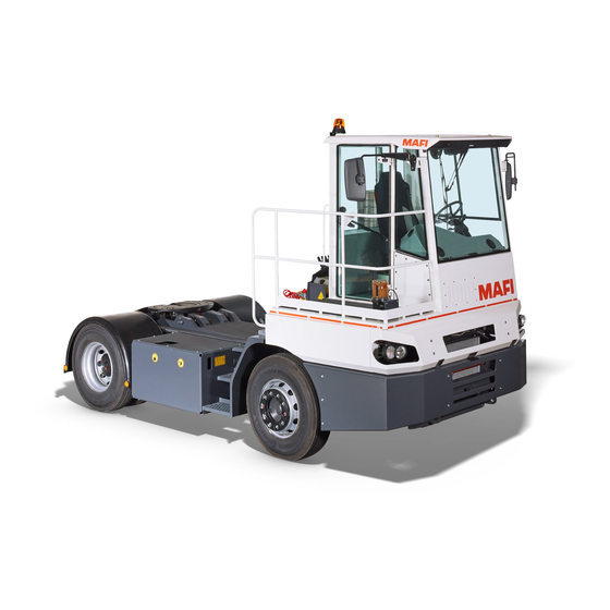
YOUR MAFI TRAC PRODUCT DESCRIPTION Product description The MT is an industrial truck with fifth wheel coupling. It is designed for the special usage requirements in terminal traffic in harbours. Operating manual T225 / T230... -
Page 31: Exterior View
YOUR MAFI TRAC EXTERIOR VIEW Exterior view 11-C26-000-010A-5 Fig. 6: Side view from driver's side 1 Pneumatics compartment 2 Windscreen washer tank 3 Hand pump for lifting/lowering the driver's cab 4 Sling points, front 5 Main battery switch 6 Battery compartment with main fuses... - Page 32 YOUR MAFI TRAC EXTERIOR VIEW 11-C26-000-011A-4 Fig. 7: View right side 1 Exhaust 2 Cabin door 3 Equalising reservoir, engine coolant 4 Sling points, front 5 Ladder 6 Oil viewing window for hydraulic oil 7 Hydraulic tank/Fuel tank 8 Sling point, rear...
-
Page 33: Interior View
YOUR MAFI TRAC INTERIOR VIEW Interior view 11-C26-067-060A-6 Fig. 8: Interior view 1 Steering wheel 2 Operator control panel 3 Operator control panel for heater/ventilation/air conditioner 4 Central electric box 5 Pedals 6 Joystick for fifth wheel 7 Driver seat... - Page 34 Operating manual T225 / T230...
-
Page 35: Operation
OPERATION Opening and closing Seating Steering wheel Mirrors Pedals Heater/Ventilation/Air Conditioner Lighting Instrument panel Operating panel for the automatic transmission Combination display instrument Vehicle electrical system Useful things Operating manual T225 / T230... -
Page 36: Opening And Closing
OPERATION OPENING AND CLOSING Opening and closing The MT comes with two keys for use on all locks on your Trac. Cabin door unlocking/locking Fig. 9: Cabin door 1 Unlock 2 locking Door opener Outside door opener Fig. 10: Outside door opener Opening Unlock the door. - Page 37 OPERATION OPENING AND CLOSING Inside door opener Fig. 11: Inside door opener 1 Door opener 2 Door handle Opening Press the door opener 1 in the direction of the arrow. Push the door open with the door handle 2. The door is open. Close Pull the door by the door handle 2 toward the inside until the door latches in.
- Page 38 OPERATION OPENING AND CLOSING Unlocking Fig. 13: Releasing the retainer 1 Release button Press the release button 1 while pulling the door out of the retainer at the same time. The door is unlocked. Windows Fig. 14: Driver-side window Opening Release the latch.
-
Page 39: Seating
OPERATION SEATING Seating Seat adjustment S e t t i n g t h e s e a t s u s p e n s i o n i s d o n e m a nu a l l y w i t h a n a d j u s t i n g k n o b o n t h e s t a n d a r d m o d e l o r a u t o m a t i c a l l y u s i n g a ir s u s p e n s i o n . - Page 40 OPERATION SEATING Seat tilt adjustment Adjust the seat angle using levers 3 and 4. Use lever 3 to adjust the front of the seat squab and lever 4 for the rear. Lift the lever. The seat is unlatched. Adjust the seat angle. Release the lever.
- Page 41 OPERATION SEATING Seat belt – optional D A N G E R ! D a n g e r o f i n j u r y ! A s e a t b e l t t h a t i s n o t wo r n o r fa s t e n e d p r o p e r l y a n d c a n n o t p r ov i d e s u f fi c i e n t p r o t e c t i o n .
-
Page 42: Steering Wheel
OPERATION STEERING WHEEL Steering wheel Note: Steering The sticker “Steering” is on the central electrical compartment. Fig. 17: Note: Steering W A R N I N G ! A c c i d e n t h a z a r d ! W i t h t h e e n g i n e o f f o r w h e n t h e hy d ra u l i c s a r e d e fe c t i ve, m o r e e f fo r t i s r e q u i r e d t o s t e e r. - Page 43 OPERATION STEERING WHEEL Combination switch The combination switch is located on left side of the steering wheel. You can use the combination switch to operate the indicators, horn, flash, high beams/low beams, and the front windscreen washer and wiper. Direction indicator/high beam Fig.
- Page 44 OPERATION STEERING WHEEL High beam/Low beam Fig. 22: Function indicator for high beam/low beam 1 High beam 2 Low beam Switch on the headlights (see “Headlight” on page 50). °C When the headlights are switched on, the low beam is °F activated.
- Page 45 OPERATION STEERING WHEEL Front windscreen wiper Fig. 23: Operation 1 Windscreen washer 2 J = Intermittent wiping not supported 3 0 = Windscreen wiper off 4 I = Normal speed 5 II = Fast speed The front windscreen wiper is operated with a rotary switch. 11-C26-067-025A-1 Use the rotary switch to operate the front windscreen wiper at two different speeds.
- Page 46 OPERATION STEERING WHEEL Rear windscreen wiper You set the rear windscreen wiper to two different speeds with switch 2. Using the switch 1 you can operate the washer unit. Fig. 24: Control elements °F 1 “Windscreen washer” switch 00000 MODE 2 “Rear windscreen wiper”...
-
Page 47: Mirrors
OPERATION MIRRORS Mirrors Inside rear-view mirror Fig. 25: Inside rear-view mirror C A U T I O N ! P r o p e r t y d a m a g e ! O b j e c t s a n d d i s t a n c e s i n t h e w i d e - a n g l e r e a r - v i ew m i r r o r a p p e a r d if fe r e n t t h a n t h ey a r e. -
Page 48: Pedals
OPERATION PEDALS Pedals The MT is equipped with a pedal unit. Fig. 26: Pedal unit 1 Accelerator 2 Brake pedal D A N G E R ! A c c i d e n t h a z a r d ! 11-C26-067-032A-4 Pe d a l s c a n b e c o m e bl o cke d by l o o s e o b j e c t s i n t h e d r i ve r ' s c a b i n . -
Page 49: Heater/Ventilation/Air Conditioner
OPERATION HEATER/VENTILATION/AIR CONDITIONER Heater/Ventilation/Air Conditioner Controls Fig. 27: Controls 1 Temperature rotary switch 2 “Air conditioner” on/off switch – optional 3 Blower switch (4-stage) The controls for the heater, ventilation and the air conditioner (optional) are installed between the footwell and the central electric box. - Page 50 OPERATION HEATER/VENTILATION/AIR CONDITIONER C A U T I O N ! L e a k s i n t h e a i r c o n d i t i o n e r ! I f t h e a i r c o n d i t i o n e r i s n o t r u n fo r a l o n g e r t i m e, t h e s l i p - r i n g s e a l o f t h e c o m p r e s s o r m ay b e c o m e b r i t t l e.
- Page 51 OPERATION HEATER/VENTILATION/AIR CONDITIONER Air outlet nozzles Fig. 29: Air outlet nozzles 1 Front window 2 Driver seat 3 Side windows There are several air outlet nozzles in the driver's cab. You can use these nozzles to defrost the windows and to ventilate the interior.
-
Page 52: Lighting
OPERATION LIGHTING Lighting Headlight Fig. 31: “Light” switch °F km/h The low beam and parking light can be switched on with a 00000 two-position switch. It is installed in the instrument panel. W A R N I N G ! A c c i d e n t h a z a r d ! A c c i d e n t s m ay o c c u r w h e n o n c o m i n g t ra f f i c i s bli n d e d by t h e g l a r e o f a h i g h - b e a m h e a d l i g h t . - Page 53 OPERATION LIGHTING Warning beacon Fig. 33: Switch for warning beacon °F °C km/h The switch is installed in the instrument panel. 00000 MODE Switching on the warning beacon Press the switch. The LED strip on the button blinks. The warning beacon is switched on. 11-C26-067-009A-5 Interior lighting The roof of the driver's cab is equipped with an interior/reading...
-
Page 54: Instrument Panel
OPERATION INSTRUMENT PANEL Instrument panel Overview 11-C26-067-038A-7 Fig. 35: Instrument panel 1 Combination switch 2 Controls 3 Steering wheel 4 Adjusting the steering wheel 5 Operating panel for the transmission 6 Combination display instrument 7 Radio compartment 8 Ignition 9 Heating/Ventilation/Air conditioner 10 Joystick for fifth wheel 11 Driver seat Operating manual T225 / T230... - Page 55 OPERATION INSTRUMENT PANEL Ignition The ignition lock is for switching the ignition on/off and starting/ stopping the engine. Fig. 36: Ignition Switch positions of the ignition lock: Ignition off (all electrical loads are switched off, ignition key can be withdrawn) MT is ready for operation (ignition is on, electrical loads such as radio, two-way radio are on, warning and control lights active)
- Page 56 OPERATION INSTRUMENT PANEL Bypassing the engine's safety switch-off The engine is automatically shut off after 30 seconds, if on the combination display instrument either the warning light “Motor oil pressure” is on, the coolant-liquid level light is on, or the pointer on the engine-coolant temperature display is at the far right.
- Page 57 OPERATION INSTRUMENT PANEL Parking brake Fig. 39: “Parking brake” switch °F 1 “Parking brake” switch km/h 00000 2 Function indicator for the “Parking Brake” Apply the brakes Press the switch down. The function indicator in the combination display instrument lights up. The parking brake is engaged. Release the brakes 11-C26-067-013A-3 Press the switch up.
- Page 58 OPERATION INSTRUMENT PANEL Rear axle differential lock Fig. 40: Additional function, rear axle differential lock °F 1 “Rear axle differential lock” button km/h 00000 2 Control light The switchable rear axle differential lock increases the traction of the MT. You can also use the switchable rear axle differential lock when starting off on a slippery surface.
- Page 59 OPERATION INSTRUMENT PANEL Manual brake for the semi-trailer – optional The manual brake for the semi-trailer is located to the left of the driver's seat. The manual brake can be used for controlled braking of the semi-trailer, e.g. on downhill slopes or ramps. Fig.
- Page 60 OPERATION INSTRUMENT PANEL Joystick for fifth wheel Fig. 42: Joystick for fifth wheel 1 Joystick 2 Lowering 3 Lifting You can lift and lower the fifth wheel using the joystick. Lowering Press the joystick in the direction of arrow 2. Fifth wheel coupling is lowered.
- Page 61 OPERATION INSTRUMENT PANEL Saddle plate height warning Fig. 44: Saddle plate height warning °F 1 Red control light 00000 2 Warning buzzer If the saddle plate sinks to a height of less than 1,425 mm during the drive and the fifth wheel coupling is engaged, a warning buzzer sounds and, simultaneously, the control light LEVEL comes on.
- Page 62 OPERATION INSTRUMENT PANEL Compressed-air fanfare horn – optional Fig. 46: "Compressed-air fanfare horn" button °F The button is located on the operator control panel. 00000 MODE 11-C26-067-018A-2 Radio – optional Fig. 47: Audio device C o n s u l t t h e m a nu fa c t u r e r ' s o p e ra t i n g m a nu a l fo r i n fo r m a t i o n o n h ow t o o p e ra t e t h e a u d i o d ev i c e.
-
Page 63: Operating Panel For The Automatic Transmission
OPERATION OPERATING PANEL FOR THE AUTOMATIC TRANSMISSION Operating panel for the automatic transmission Overview The setting of the driving direction, the selection of the driving program and the reading of the oil level or the error code can be done with the operating panel. Fig. - Page 64 OPERATION OPERATING PANEL FOR THE AUTOMATIC TRANSMISSION W A R N I N G ! A c c i d e n t h a z a r d ! U n c o n t r o l l e d r o l l i n g M T c a n s e r io u s l y i n j u r e p e r s o n s. D o n o t l e t t h e M T r o l l i n n e u t ra l p o s i t i o n .
- Page 65 OPERATION OPERATING PANEL FOR THE AUTOMATIC TRANSMISSION Driving gear reverse Fig. 50: Reverse driving Select the driving gear “Reverse” by pressing the button R. A l way s s h i f t f r o m t h e n e u t ra l p o s i t i o n ( i d le p o s i t i o n ) a n d w i t h w h e e l s s t a n d i n g s t i l l i n t o t h e d r i v i n g g e a r R .
- Page 66 OPERATION OPERATING PANEL FOR THE AUTOMATIC TRANSMISSION Driving gear Drive Fig. 52: Driving gear Drive (normal operation) To drive forwards, select the driving gear “Drive”. Select the driving gear “Drive” by pressing the button D. In the driving gear D, the transmission shifts automatically from the first to the fourth gear.
- Page 67 OPERATION OPERATING PANEL FOR THE AUTOMATIC TRANSMISSION Selecting higher or lower driving range For unusual driving situations such as steep slopes, a lower driving range can be selected in order to prevent an unwanted shifting up of the transmission On inclines on the other hand, shifting is possible again into a higher driving range from a previously selected lower driving range.
- Page 68 OPERATION OPERATING PANEL FOR THE AUTOMATIC TRANSMISSION MODE key Fig. 54: Additional function 1 MODE key 2 MODE-ON LED indicator The MODE key has two functions: With the MODE key 1, a programmed additional function can be switched on. For control, MODE-ON LED indicator 2, located in the MODE key, lights up.
- Page 69 OPERATION OPERATING PANEL FOR THE AUTOMATIC TRANSMISSION Fo r f u r t h e r i n fo r m a t i o n o n r e a d i n g o u t t h e o il l eve l f r o m t h e “...
- Page 70 OPERATION OPERATING PANEL FOR THE AUTOMATIC TRANSMISSION With the motor running, press arrow keys 1 and 2 simultaneously twice. With the motor off, press arrow keys 1 and 2 simultaneously once. You are now in the diagnostics mode. Display 5 shows the error code in the first storage location, “d1”.
-
Page 71: Combination Display Instrument
OPERATION COMBINATION DISPLAY INSTRUMENT Combination display instrument Overview °C °F km/h 00000 11-C26-067-044A-2 Fig. 57: Combination display instrument The combination display instrument is located on the instrument panel and displays control functions and warning lights. Control function indicators Fig. 58: Control lights 1 Direction indicators MT 2 High beam °C... - Page 72 OPERATION COMBINATION DISPLAY INSTRUMENT Warning lights Fig. 59: Warning lights 1 Yellow engine warning light 2 Red engine warning light °C 3 Motor oil pressure °F 4 Malfunction of air reserve pressure (collective error cycle 1 to 2) km/h 00000 5 Level of engine coolant water 6 Intake air filter soiling (option) 7 Transmission malfunction...
- Page 73 OPERATION COMBINATION DISPLAY INSTRUMENT Engine warning lights The warning lights are on the combination display instrument. The warning lights flash briefly during ignition and then go out again. Fig. 60: Yellow “engine” warning light If the yellow warning light lights up, then °C there is an engine malfunction.
- Page 74 OPERATION COMBINATION DISPLAY INSTRUMENT Motor oil pressure Fig. 62: Warning light “Motor oil pressure” The warning light is on the combination display instrument. °C This warning light lights up during ignition. This warning light °F should go out once the engine has started up. km/h 00000 If the warning light does not go out after the engine has...
- Page 75 OPERATION COMBINATION DISPLAY INSTRUMENT Engine coolant level Fig. 64: Warning light “Engine coolant level” The warning light is on the combination display instrument. °C During ignition, the warning light lights up for several seconds °F and then goes out. km/h 00000 If the warning light remains on after ignition or goes on during operation, then the engine coolant level in the equalising...
- Page 76 OPERATION COMBINATION DISPLAY INSTRUMENT Engine coolant temperature Fig. 65: Engine coolant temperature indicator This indicator is operational when the ignition is on. The engine shuts off automatically if the engine coolant °C overheats and the pointer is at the far right beyond the permitted temperature range.
- Page 77 OPERATION COMBINATION DISPLAY INSTRUMENT Transmission malfunction Fig. 67: Warning light “Transmission malfunction” The warning light is on the combination display instrument. °C During ignition, the warning light is on for several seconds and °F km/h then it should go out. 00000 If the control light does not go out after ignition or remains on during operation, then there is a problem with the...
- Page 78 OPERATION COMBINATION DISPLAY INSTRUMENT Transmission oil temperature Fig. 69: Warning light “Transmission oil temperature” The warning light is on the combination display instrument. °C If this warning light goes on during operation, then the oil °F temperature in the transmission is too high. This can occur if km/h 00000 the transmission oil level is low or when the transmission...
- Page 79 OPERATION COMBINATION DISPLAY INSTRUMENT Speedometer Fig. 71: Speedometer 1 Driving speed 2 Operating hours counter The driving speed is displayed in two units. grey = display in km/h (kilometres per hour) yellow = display in mph (miles per hour) km/h km/h The operating hour counter can be found on the lower part of 00000 00...
-
Page 80: Vehicle Electrical System
OPERATION VEHICLE ELECTRICAL SYSTEM Vehicle electrical system Main battery switch The main battery switch is on the left side of the vehicle on the ladder between the steps. It breaks the electrical connection to the vehicle battery. C A U T I O N ! M a t e r i a l d a m a g e ! Tu r n i n g o f f t h e m a i n b a t t e r y sw i t c h c a n d a m a g e t h e g e n e ra t o r, t h e e l e c t r i c a l e q u i p m e n t a n d t h e c o n t r o l l e r s. - Page 81 OPERATION VEHICLE ELECTRICAL SYSTEM Vehicle fuses Fig. 74: Central electric box The electrical fuses for the vehicle are located on the right side of the operator in a fuse box. Consult the circuit diagram for the exact configuration. 11-C26-019-008A-2 External start socket Fig.
-
Page 82: Useful Things
OPERATION USEFUL THINGS Useful things Compartments Fig. 76: Stowing compartment above the central electric box The compartments for stowing loose objects are located next to the driver's seat and above the central electric box. 11-C26-067-054A-3 Fig. 77: Stowing compartment next to driver's seat 11-C26-067-054A-1 12 volt connections Fig. - Page 83 OPERATION USEFUL THINGS Ashtray The ashtray is located underneath the side window on the driver's side. Fig. 79: Ashtray 11-C26-067-062A-1 Opening Pull the flap in the direction of the arrow 1 Removing Push the ashtray down (arrow direction 2) and open it at the same time.
- Page 84 OPERATION USEFUL THINGS Sun visor The sun visor on the windscreen protects you from being blinded during driving. Fig. 80: Sun visor Lowering the roller blind Pull the roller blind in the direction of arrow 1 until it reaches the desired position. Raising the roller blind Pull the cord briefly in the direction of arrow 2 and then let The roller blind returns to its original position.
-
Page 85: Operation
OPERATION Starting check Starting the engine Gear shifting Driving instructions Turn off engine Working with coupling equipment Operation with container chassis Winter operation Maintenance Operating manual T225 / 230... -
Page 86: Starting Check
OPERATION STARTING CHECK Starting check To retain the value of the MT, keep it operational and safe to work with, it is absolutely necessary that you conduct various inspections. The following is a list of inspections. W A R N I N G ! D a n g e r o f i n j u r y ! N e g l e c t e d o r i n s u f f i c i e n t i n s p e c t i o n s c a n l e a d t o c o n s i d e ra bl e p e r s o n a l i n j u r y a n d p r o p e r t y d a m a g e o n... - Page 87 OPERATION STARTING CHECK Checking the tightening torques of the wheel nuts W A R N I N G ! A c c i d e n t h a z a r d ! B e fo r e i n i t i a l o p e ra t i o n o r a f t e r a w h e e l c h a n g e, t h e w h e e l nu t s c a n l o o s e n d u e t o m a t e r i a l s e t t l i n g a n d l e a d t o s e r i o u s a c c i d e n t s w i t h p e r s o n a l i n j u r i e s.
- Page 88 OPERATION STARTING CHECK Daily checks before starting the engine Carry out the following inspections each day before operating the MT. Check the entire tractor for externally visible damage and irregularities. Tyres/Wheels Check the tyres for the following: Objects stuck in the tyres Correct air pressure (10 bar when the tyres are cold) Deformations, bulges Damaged wheel rims...
- Page 89 OPERATION STARTING CHECK Loss of oil or fluid Look under the MT and check if you see pools of oil and/or water. If this is the case, check more thoroughly and find the cause. Possible sources are: Oil loss – engine, transmission, axle transmission, Loss of coolant –...
- Page 90 OPERATION STARTING CHECK Fig. 85: Equalising reservoir Check the engine coolant level. The coolant level should always lie between the “MIN” and “MAX” markings. Refill with engine coolant if necessary. Use with a mixture of water and anti-freeze/corrosion protection agent. 11-C26-061-005A-2 I f c o o l a n t h a s t o b e r e f i l l e d r e g u l a r l y, h ave q u a l i f i e d t e c h n i c i a n s c h e ck a n d r e p a i r t h e c o o li n g s y s t e m fo r...
- Page 91 OPERATION STARTING CHECK Fig. 87: Oil dip stick and oil filler neck 1 Oil filler nozzle 2 Oil dip stick Pull the oil dip stick 2. Wipe the oil dip stick 2 with a clean, lint-free cloth. Reinsert the oil dip stick 2 completely. Pull the oil dip stick 2 out again.
- Page 92 OPERATION STARTING CHECK Hydraulic oil level The hydraulic oil tank is located on the vehicle's right side. To check the oil level, you need to lower the fifth wheel completely. Fig. 89: Oil viewing window Use the oil viewing window to check the oil level. The oil level should lie between the “MIN”...
- Page 93 OPERATION STARTING CHECK Daily checks after starting the engine Transmission oil level C A U T I O N ! Tr a n s m i s s i o n d a m a g e ! I f t h e o il l eve l i s t o o h i g h o r to o l ow, t h i s c a n r e s u l t i n d a m a g e t o t h e t ra n s m i s s i o n .
- Page 94 OPERATION STARTING CHECK W A R N I N G ! A c c i d e n t h a z a r d ! I f yo u l e ave t h e M T w h i l e t h e e n g i n e i s r u n n i n g , t h e M T c a n s t a r t r o l l i n g u n i n t e n t i o n a l l y a n d s e r i o u s l y i n j u r e p e r s o n s.
- Page 95 OPERATION STARTING CHECK Fig. 92: Read the dip stick 1 Oil filler nozzle 2 Oil dip stick 3 HOT CHECK range If necessary, refill oil into the oil filler nozzle or drain oil. The oil level should lie in the “HOT CHECK” range between the “HOT-ADD”...
- Page 96 OPERATION STARTING CHECK Reading out oil level at “Oil level mode” display The transmission is equipped with an oil level sensor. You can read out the oil level and the oil level sensor errors on the “Oil level mode” display in the operating panel for the transmission. Make sure that the operating temperature between 70 °C and 90 °C has been reached.
- Page 97 OPERATION STARTING CHECK Oil level sensor Cause error oL 0X Settling time too short Setting time is too short oL EL Engine speed Low Motor speed is too low oL EH Engine speed High Motor speed is too high oL SN Select Neutral Not in neutral oL TL...
- Page 98 OPERATION STARTING CHECK Regular inspections Air dryer Fig. 94: Air dryer cartridge The air dryer is located on the left front side of the MT under the cabin. The air dryer – using an air dryer cartridge – dries the compressed air that the compressor supplies. This makes it unnecessary to add anti-freeze agent for the compressed air system.
- Page 99 OPERATION STARTING CHECK Inspecting the air dryer Open the dewatering valve of the compressed air tank by pulling the ring in the direction of the arrow. If water comes out, then all compressed air tanks need to be dewatered. Check a couple days later whether water comes out of the compressed air tanks.
-
Page 100: Starting The Engine
OPERATION STARTING THE ENGINE Starting the engine C A U T I O N ! M a t e r i a l d a m a g e ! Tr y i n g t o s t a r t t h e e n g i n e t o o m a ny t i m e s w i t h i n a s h o r t p e r io d c a n d a m a g e t h e s t a r t e r a n d t h e b a t t e r y. - Page 101 OPERATION STARTING THE ENGINE Starting procedure Fig. 97: Preheater control light Make sure that the transmission is shifted to the “Neutral” position and the gas pedal is not operated. °C °F Turn the ignition key to position I. km/h 00000 Wait until the control light of the preheater control is off.
-
Page 102: Gear Shifting
In the driving gear drive (normal operation) the transmission shifts automatically from the first through to the fourth gear. If the MT is equipped with the MAFI Eco Mode (MEM), then the automatic transmission has five forward gears and one reverse gear. - Page 103 OPERATION GEAR SHIFTING W A R N I N G ! A c c i d e n t h a z a r d ! U n c o n t r o l l e d r o l l i n g M T c a n s e r i o u s l y i n j u r e p e r s o n s. D o n o t l e t t h e M T r o l l i n n e u t ra l p o s i t i o n .
-
Page 104: Driving Instructions
OPERATION DRIVING INSTRUCTIONS Driving instructions Parking Putting the MT in gear does not secure it from rolling away. Always shift into neutral and apply the parking brake before exiting the MT. Always apply the parking brake as soon as the MT has come to a stop, the driver's seat is unoccupied or the MT has been parked. - Page 105 OPERATION DRIVING INSTRUCTIONS Make sure all warning lights have gone out. Make sure the air pressure in the compressed-air tank is sufficient. T h e M T i s r e a d y fo r o p e ra t i o n , o n l y w h e n t h e a i r p r e s s u r e i n t h e c o m p r e s s e d a ir ta n k i n t h e t h i r d c i r c u it i s m o r e t h a n 5 .
- Page 106 OPERATION DRIVING INSTRUCTIONS Make sure there is enough lateral clearance when driving around obstacles. Make sure the maximum total weights that are allowed for the trailer and the coupled load are not exceeded. Make sure that trailers drawn on tow bars are only attached with the appropriate trailer coupling.
- Page 107 OPERATION DRIVING INSTRUCTIONS Driving with rear axle differential lock The rear axle differential lock is used to prevent any single wheel from free-spinning on slippery ground. D A N G E R ! A c c i d e n t h a z a r d ! T h e M T i s le s s r e s p o n s ive t o s t e e r i n g m ove m e n t s w h e n t h e r e a r a xl e d if fe r e n t i a l l o ck i s e n g a g e d .
- Page 108 Refuelling C A U T I O N ! E n g i n e d a m a g e ! U n s u i t a bl e a n d c o n t a m i n a t e d f u e l c a n d a m a g e t h e i n j e c t i o n s y s t e m a n d t h e f u e l p u m p.
-
Page 109: Turn Off Engine
OPERATION TURN OFF ENGINE Turn off engine C A U T I O N ! E n g i n e d a m a g e ! Tu r n i n g o f f t h e e n g i n e t o o e a r l y c a n c a u se h e a t bu i l d - u p a n d d a m a g e t h e e n g i n e. -
Page 110: Working With Coupling Equipment
OPERATION WORKING WITH COUPLING EQUIPMENT Working with coupling equipment Fifth wheel coupling Hitching semi-trailers D A N G E R ! D a n g e r o f i n j u r y ! Pe o p l e c a n b e s eve r e l y i n j u r e d by b e i n g c r u s h e d d u r i n g s h u n t i n g . - Page 111 OPERATION WORKING WITH COUPLING EQUIPMENT C A U T I O N ! M a t e r i a l d a m a g e ! O b s t a c l e s a b ove t h e t ra i l e r c a n c a u s e d a m a g e w h e n l i f t i n g w i t h t h e f i f t h w h e e l c o u p l i n g .
- Page 112 OPERATION WORKING WITH COUPLING EQUIPMENT Unhitching semi-trailers Fig. 102: Controls °F 1 “Fifth wheel coupling” switches km/h 00000 2 “Fifth wheel coupling” control light 3 “Kingpin” control light T h e f i f t h w h e e l c o u p l i n g c a n o n l y b e o p e n e d w h e n t h e M T i s a t a s t a n d s t i l l .
- Page 113 OPERATION WORKING WITH COUPLING EQUIPMENT Gooseneck – optional Fig. 103: Gooseneck For towing roll trailers, the MT has to be equipped with a gooseneck. Only MTs with double-action lift cylinders can perform transport work with the gooseneck. C A U T I O N ! M a t e r i a l d a m a g e ! M a t e r i a l d a m a g e i s p o s s i ble i f t h e p e r s o n n e l d o n o t h ave a ny p ra c t i c a l ex p e r i e n c e i n o p e ra t i n g t h e...
- Page 114 OPERATION WORKING WITH COUPLING EQUIPMENT Towing and shunting coupling With the front or rear tow hitch, the MT may only be towed or perform a tow operation. W A R N I N G ! D a n g e r o f i n j u r y ! T h e r e i s a c o n s i d e ra bl e d a n g e r o f i n j u r y a n d d a m a g e, i f yo u u s e t ow i n g a n d s h u n t i n g c o u p l i n g s t o p u l l t ra i l e r s.
-
Page 115: Operation With Container Chassis
OPERATION OPERATION WITH CONTAINER CHASSIS Operation with container chassis Loading and unloading procedure A container chassis can be hitched to the MT for traffic in a terminal. The container chassis can be saddled and unsaddled like a semi-trailer on the MT, see “Fifth wheel coupling”... -
Page 116: Winter Operation
OPERATION WINTER OPERATION Winter operation If you intend to operate the MT at low temperatures, a few precautionary measures and checks are necessary. Have the concentration of corrosion protection and anti- freeze agents in the engine coolant checked. Add anti-freeze agent to the windscreen washer water. Have the battery checked. -
Page 117: Maintenance
OPERATION MAINTENANCE Maintenance Regular maintenance retains the value of your MT. For cleaning, use commercially available vehicle care products from vehicle supply stores. Exterior vehicle care The best protection for the MT against hazardous environmental influences is washing and conserving the vehicle often. - Page 118 OPERATION MAINTENANCE Operating manual T225 / 230...
-
Page 119: Transport
TRANSPORT Loading onto a flatbed trailer Loading with a crane Operating manual T225 / T230... -
Page 120: Loading Onto A Flatbed Trailer
TRANSPORT LOADING ONTO A FLATBED TRAILER Loading onto a flatbed trailer Flatbed trailers or rail carriages, for example, can be used to transport the MT over longer distances. Make sure that the transport units can carry the weight of the (see “Vehicle identification plate”... -
Page 121: Loading With A Crane
TRANSPORT LOADING WITH A CRANE Loading with a crane The MT has sling points for loading by crane. Two sling eyes are located behind the driver's cabin and a third sling point is the tow hitch in the rear. Fig. 106: Sling points 11-C26-017-010A-6 Lifting Fig. - Page 122 Fig. 109: Crane load/Chain lengths 1 Crane load: 10,000 kg 2 Chain length, front: 2.64 m 3 Chain length, rear: 3.84 m Fasten the lifting gear to the appropriate sling points. The MT can now be carefully lifted and loaded. 11-C26-017-010A-5 T h e M T t i l t s s l i g h t l y fo r wa r d w h e n l i f t e d , s o t h a t t h e h o i s t i n g e q u i p m e n t d o e s n o t d a m a g e t h e d r i ve r ' s c a b in .
-
Page 123: Self-Help
SELF-HELP Electrical system Fifth wheel coupling Start aid Displays of the combination display instrument Reading the engine error codes Emergency operation function in MAFI ECO MODE – optional Towing Inflating the tyres Operating manual T225 / T230... -
Page 124: Electrical System
SELF-HELP ELECTRICAL SYSTEM Electrical system Fuses Fig. 110: Central electric box The electrical fuses for the vehicle are located next to the cabin door under the removable cover. If there are problems with electrical equipment, then: Remove the cover. Check the fuses. Consult the circuit diagram for the exact configuration of the fuses. -
Page 125: Fifth Wheel Coupling
SELF-HELP FIFTH WHEEL COUPLING Fifth wheel coupling Fig. 111: Emergency hitch release In an emergency, the fifth wheel coupling of the MT can be unhitched even without the engine running or without electricity by using the emergency hitch release. The emergency hitch release is located on the left side of the fifth wheel coupling. -
Page 126: Start Aid
SELF-HELP START AID Start aid External start socket Fig. 112: External start socket The external start socket is located in the battery compartment. With the external start socket, a jumper cable can be connected for giving or receiving help with starting up. 11-C26-019-013A-3 Operating manual T225 / T230... -
Page 127: Displays Of The Combination Display Instrument
SELF-HELP DISPLAYS OF THE COMBINATION DISPLAY INSTRUMENT Displays of the combination display instrument Indicator Possible cause Proposed solution Warning light “Motor oil pressure” is on Oil pressure too low Inspect MT for oil loss, if necessary, have cause of oil leak eliminated. Check oil level and refill, if necessary. - Page 128 SELF-HELP DISPLAYS OF THE COMBINATION DISPLAY INSTRUMENT Indicator Possible cause Proposed solution Insufficient air flow through the Have the fan blades cleaned, consult radiator the maintenance manual. Warning light “Transmission” is on Transmission malfunction Have it repaired by customer service. Yellow warning light “Engine malfunction”...
-
Page 129: Reading The Engine Error Codes
SELF-HELP READING THE ENGINE ERROR CODES Reading the engine error codes In case of an engine problem, the engine controller displays error codes in the form of flash sequences. You can read the error codes with the “Diagnostics on/off” and “Diagnostics selection”... - Page 130 SELF-HELP READING THE ENGINE ERROR CODES Press the “Diagnostics on/off” switch 2 to ON. The error reading is activated. Scroll the “Diagnostics selection” rocker switch 1 back and forth. You receive the error codes: No engine malfunction, if the yellow and red warning lights are constantly on. Engine malfunction present, if the yellow and red warning lights are on shortly and then the yellow warning light flashes and the red warning light...
-
Page 131: Emergency Operation Function In Mafi Eco Mode - Optional
Emergency operation function in MAFI ECO MODE – optional If the engine controller and/or CAN bus fails in MAFI ECO MODE (MEM), the engine speed decreases to 750 rpm. This speed corresponds to the idle speed and the MT only moves very slowly or stops moving. -
Page 132: Towing
SELF-HELP TOWING Towing The MT may only be towed in an emergency and for short distances at a maximum speed of 10 km/h out of a danger area. The following needs to be observed thereby: The maximum towing distance of 2 km may not be exceeded if the engine is running. - Page 133 Unscrew the bolts 1 of the emergency release unit on all rear wheels with spring accumulator brake actuator completely. Towing the MAFI Trac W A R N I N G ! A c c i d e n t h a z a r d ! Tow i n g i s m o r e d if f i c u l t d u e t o i n c r e a s e d s t e e r i n g e f fo r t a n d n o b ra ke p ow e r.
-
Page 134: Inflating The Tyres
SELF-HELP INFLATING THE TYRES Inflating the tyres Fig. 115: Tyre-inflating connection The tyre-inflating connection can be used for filling the tyres in an emergency. Start the engine. Remove the protection cap from the tyre-inflating connection 1. Attach the tyre-inflating hose (not part of the scope of 11-C26-020-007A-3 delivery). -
Page 135: Technical Data
TECHNICAL DATA Dimensions (standard model) Weights General information Hydraulic system Brake system Operating manual T225 / T230... -
Page 136: Dimensions (Standard Model)
TECHNICAL DATA DIMENSIONS (STANDARD MODEL) Dimensions (standard model) Fig. 116: Dimensions T225/T230 Dimensions depending on wheel base Wheelbase Standard 3,000 mm 5,270 mm 1,860 mm 2,190 mm Operating manual T225 / T230... - Page 137 TECHNICAL DATA DIMENSIONS (STANDARD MODEL) Fig. 117: Dimensions T225/T230 Dimensions depending on tyres Tyres 10R20& 11R20& 315/60R22.5 11R22.5 12R22.5 925 mm 940 mm 880 mm 1,125 mm 1,135 mm 995 mm 1,585 mm 1,600 mm 1,530 mm 2,060 mm 2,075 mm 2,005 mm 3,295 mm 3,310 mm...
-
Page 138: Weights
TECHNICAL DATA WEIGHTS Weights T225 T230 Empty weight 7,600 kg 7,600 kg Permissible coupled load at 6 km/h (standard tyres) 25,000 kg 32,000 kg System weight (trac + trailer + load) 80,000 kg 90,000 kg Operating manual T225 / T230... -
Page 139: General Information
TECHNICAL DATA GENERAL INFORMATION General information T225 T230 Maximum speed approx. 40 km/h approx. 40 km/h Engine power according to ISO 3046 Cummins QSB 6.7-C173 (standard) at 2,200 rpm 129 kW (173 hp) 129 kW (173 hp) Cummins QSB QSB 6.7-C220 at 2,000 rpm 172 kW (230 hp) 172 kW (230 hp) Starting tractive force in 1st gear (standard motor) -
Page 140: Hydraulic System
TECHNICAL DATA HYDRAULIC SYSTEM Hydraulic system Two double-action hydraulic cylinders for front axle steering. Two single-action hydraulic cylinders (optional double-action) for lifting the fifth wheel coupling. T225 T230 Pump capacity at 2,200 rpm 70 l/min 70 l/min Max. continuous pressure Steering 175 bar 175 bar... -
Page 141: Brake System
TECHNICAL DATA BRAKE SYSTEM Brake system Dual line brake system with dual-line trailer brake connector T225/T230 Front axle pneumatically actuated Rear axle pneumatically actuated Parking brake spring-loading unit acting on the rear axle Operating manual T225 / T230... - Page 142 TECHNICAL DATA BRAKE SYSTEM Operating manual T225 / T230...
- Page 143 Interior lighting Rear axle differential lock Door console Suspended loads Radio console Driving instructions Joystick for fifth wheel Emergency operation function MAFI ECO MODE (MEM) Engine Engine warning lights Parking MAFI ECO MODE (MEM) Reading error codes Emergency operation function Starting...
- Page 144 Steering wheel adjustment Sun visor Oil dip stick Motor oil 92, 93 Transmission oil Technical data Oil filler nozzle Brake system Motor oil Dimensions Oil viewing window General information Operating panel for automatic transmission Hydraulic system Weights Operation with container chassis Tightening torques of the wheel nuts Towing and shunting coupling Parking brake...
Need help?
Do you have a question about the Trac T225 and is the answer not in the manual?
Questions and answers