Table of Contents
Advertisement
Quick Links
Advertisement
Table of Contents

Related Manuals for BEN-RI Hydra II Series

Summary of Contents for BEN-RI Hydra II Series
- Page 3 Hydra II /Piccolo II - Version 5.40 Febrary 2017 www.lt-light.com...
- Page 4 Reproduction and distribution of all or part of this document will require the written approval of Ben-Ri Electrónica SA (www.ben-ri.com www.lt-light.com ) as the owner of the document. This document is made to help the use of concrete equipment, with a specific software version.
-
Page 5: Table Of Contents
MODELS, PRESENTING AND CONNECTIONS 1.1. HYDRA II & PICCOLO II ......................................1-1 1.2. TECHNICAL CHARACTERISTICS .................................. 1-3 1.2.1. GENERAL ........................................... 1-3 1.2.2. ELECTRIC CHARACTERISTICS & AMBIENT ..........................1-4 1.3. TECHNICAL SERVICE ......................................1-5 1.4. INSTALLATION & START UP ..................................1-5 1.4.1. CONFIGURATION OF MONITORS –... - Page 6 EDITOR ................5-1 CHANNELS ............................................. 5-1 5.1.1 CHANNELS SELECTION ....................................5-1 5.1.2 LEVEL EDITION ........................................5-2 5.1.3 QUICK SELECTIONS ....................................... 5-3 5.1.4 REMOVING CHANNELS ....................................5-3 5.1.5 SELECTIONS & LEVELS FROM EXTERNAL DISPLAY ....................5-3 5.1.6 INVERT FUNCTION ......................................5-4 5.1.7 EDITION IN MANUAL MODE - VENTANA SUB ........................
- Page 7 6.6.6 MODIFYING A RANGE OF CUES/GROUPS ..........................6-10 6.6.7 COPYING CUES/GROUPS..................................6-13 6.6.8 EXCHANGING CUES/GROUPS ................................6-13 TIMES ............................................. 6-14 6.7.1 TIMES & TIMING FOR CUES/GROUPS ............................6-14 TIMING ............................................6-15 6.8.1 SET THE DEFAULT TIMING ................................... 6-17 TIME PARTS FOR CUES ....................................6-18 6.9.1 CREATING TIME PARTS FOR A CUE............................
- Page 8 8.5.4 EXAMINING A PAGE ....................................8-12 8.5.5 LOADING PAGES IN SUBMASTERS ............................8-13 8.5.6 LOADING PAGE IN A/B SEQUENCER ............................8-13 8.5.7 LOADING PAGES IN SUBMASTER & SEQUENCER ....................... 8-13 8.5.8 LOADING PAGES FROM BANK KEYS ............................8-13 8.5.9 FUNCTIONS ABOUT THE CURRENT PAGE ..........................8-13 8.5.10 MORE FUNTIONS FOR PAGES .................................
- Page 9 MACROS ................11-1 11.1 EDITING MACROS ........................................11-1 11.2 MODIFYING A MACRO ......................................11-2 11.3 EXAMINING A MACRO ......................................11-3 11.4 DELETING A MACRO ......................................11-3 11.5 COPYING & ECHANGING MACROS ................................. 11-3 11.6 PLAYBACK ............................................ 11-4 11.6.1 FROM EDITOR ........................................11-4 11.6.2 FROM A CUE COMMAND ..................................
- Page 10 MENUS ................14-1 14.1 SHOW MENU ........................................... 14-2 14.1.1 THE DATA OF SHOW ....................................14-2 14.1.2 PRINTING DATA ......................................14-7 14.1.3 AUTOSAVE ........................................... 14-8 14.1.4 SHOW CONVERTER..................................... 14-9 14.2 USER SETUP ........................................... 14-9 14.2.1 EDITOR & TIMES ......................................14-9 14.2.2 PLAYBACKS ........................................14-10 14.2.3 SYSTEM ...........................................
- Page 11 17.2 CLONING FUNCTIONS ....................................17-14 17.2.1 CLONING & REPLACE ....................................17-15 17.2.2 CLONING & INSERT ....................................17-17 17.2.3 CLONING & MOVE ......................................17-19 SERIAL PORT RS232- DEVICES ....18-1 18.1 PORT CONFIGURATION ....................................18-2 18.2 CACHE LIST ..........................................18-2 18.3 DEVICE EDITION ........................................18-2 18.3.1 CREATION OF A NEW DEVICE ................................
- Page 12 23.2 MENU MONITOR – SIMULATOR ................................. 23-3 23.3 FUNCTIONS & EXTERNAL KEYBOARD ............................23-4 23.4 WORKING WITH WOLE ....................................23-6 24. ETHERNET ..............24-1 24.1 CONNECTING… ........................................24-1 24.2 SET THE IP OF HYDRA II ..................................... 24-3 24.3 SET THE IP OF PICCOLO II ..................................24-4 24.4 SET THE IP OF WOLE (SIMULATOR) ..............................
- Page 13 …..& SOME ANNEXES HYDRA II / PICCOLO II ANNEX – LANGUAGUE & KEYBOARD ANNEX – TRANSLATE ANNEX – SOFTWARE UPDATING …..& SOME ANNEXES HYDRA II ANNEX – BIOS ANNEX – PASSWORD ANNEX – SOLVING THE QUESTION OF IPIRP ERROR – LOG FILE ANNEX –...
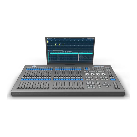
- Page 15 1. MODELS, PRESENTING AND CONNECTIONS 1.1. HYDRA II & PICCOLO II Hydra II: Natural evolution of Hydra family (Space, Sky & Spirit). Same functionality and enhancement of: control power, control channels, Dmx addresses, and an improved graphical and intuitive user interface. There are four different models: 24 Submasters, 3 physical DMX outputs, and a total of 6 Ethernet DMX outputs 1536 directions to control channels and fixture attributes by 3 x DMX XLR5...
- Page 16 MODELS, PRESENTING AND CONNECTIONS Piccolo II: It based in the principles of use of the Hydra II family. Same functionality created to cover needs and budgets mote tighter, but inheriting the philosophy of Hydra II. There are four different models: 24 Submasters, 1 physical DMX outputs, and a total of 2 Ethernet DMX outputs 512 directions to control channels and fixture attributes by 1 x DMX XLR5 Piccolo II...
-
Page 17: Models, Presenting And Connections
MODELS, PRESENTING AND CONNECTIONS 1.2. TECHNICAL CHARACTERISTICS 1.2.1. GENERAL HYDRA II-3000 HYDRA II-6000 CAPACITY & PICCOLO II-1000 S24/S48 S24/S48 S24/S48 INTERFACES Control channels configurable as conventional channels or 1024 3072 6144 moving lights parameters. DMX output on XLR5 (on 1 (2) 3 (6) 6 (12) -
Page 18: Electric Characteristics & Ambient
MODELS, PRESENTING AND CONNECTIONS *special libraries for all *special libraries for all *special libraries for all parameters & channels parameters & channels parameters & channels Free Keys (accesses to any item) Special function for moving FLIP, FAN, FINE, FLIP, FAN, FINE, FLIP, FAN, FINE, HOME, ORTO…... -
Page 19: Technical Service
MODELS, PRESENTING AND CONNECTIONS 1.3. TECHNICAL SERVICE MADRID/Spain: BEN-RI Electrónica S.A. Pol. Ind. Ventorro del Cano C/. Lozoya Nº 8 28925 Alcorcón, Madrid Tel: 91 472 06 66 You can obtain a updated list of technicals service points in www.lt-light.com... - Page 20 MODELS, PRESENTING AND CONNECTIONS Connect external mouse & keyboard to the USB port, or to the Mouse & Keyboard ports, (in accordance with your mouse & keyboard). ALWAYS CONNECT THE MOUSE Piccolo II systems only have USB port OR THE EXTERNAL KEYBOARD to connect mouse &...
-
Page 21: Configuration Of Monitors - Hydra Ii
MODELS, PRESENTING AND CONNECTIONS 1.4.1. CONFIGURATION OF MONITORS – HYDRA II You will need to configure monitors if this is the first time you connect one / two DVI displays and touch screen does not respond properly Always connect the monitors (1 or 2) before turning on the console Turn on the console The access to monitors configuration is in Set the touch panel (Generic Non-PnP Monitor, of 800x480) as Main Display and locate it, dragging with... -
Page 22: Configuration Of Language & Keyboard
MODELS, PRESENTING AND CONNECTIONS 1.4.2. CONFIGURATION OF LANGUAGE & KEYBOARD If you are connecting a external keyboard of other language that the configured, you need to configurate it, also, it’s possible to configure the system idioma. button allows to us accessing to the configuration tool of the keyboard and language. You can access to this tool from: Console will stop with its normal function during the configuration process. - Page 23 MODELS, PRESENTING AND CONNECTIONS Piccolo II – Linux opens keyboard-configuration [Configuración de keyboard] system tool. Inside this tool you must use the external keyboard: Moving the cursor with the arrow keys Pressing Tab to toogle betwen list options: <Accept> y <Cancel> In this first window, select the type of keyboard connected to the console.
-
Page 24: Connections
1-10 MODELS, PRESENTING AND CONNECTIONS 1.5. CONNECTIONS 1.5.1. Main supply: Hydra II Piccolo II IEC base for 90-260V / 50-60 Hz 2.5A. Always, IEC base for 90-260V / 50-60 Hz 1.5A. Always, used normalized cables (confirm the ground plug). used normalized cables (confirm the ground plug). -
Page 25: Smpte Input
MODELS, PRESENTING AND CONNECTIONS 1-11 1.5.3. SMPTE input PICCOLO II-1000 HYDRA II-3000 HYDRA II-6000 S24/S48 S24/S48 S24/S48 SMPTE Stereo jack for 1Vpp SMPTE signals. The SMPTE input responds to the formats: 24, 25, 30 & 30 drop frame without adjusts. Code: 1 –... -
Page 26: Reset Pushbutton (Rst)
1-12 MODELS, PRESENTING AND CONNECTIONS 1.5.7. Reset Pushbutton (RST) This button is placed in the console If by some circumstance your console did not switch off, it must front, close to the LED of PWR & be pushed this button to force a disconnection of the battery. MAINS. -
Page 27: About This User Manual
2. ABOUT THIS USER MANUAL 2.1. CONVENTIONS Concepts and general functions are identified by their names, as A/B, BANKS… Physical keys are identified as your corresponding icon The action of click over a key, is represented in the same way that the key This icon identified the action of to press and hold down pressed the key ... -
Page 28: Function Keys
2-2 ABOUT THIS USER MANUAL 2.2. FUNCTION KEYS Each function has an associated key. In most console models each function has its corresponding physical key. But working with the simulator (wole), a Wing, or a Piccolo II system, not all the function has their corresponding physical key. -
Page 29: Menus
ABOUT THIS USER MANUAL 2-3 Touch panel also shows menus and other screens… If BANK keys aren’t on touch, please, close any other window clicking on 2.4. MENUS To open the list of menus Open the menus list pressing from the external keyboard press Home. -
Page 30: Options Windows
2-4 ABOUT THIS USER MANUAL Important! In the title part of the Menu list you can find the current software version & the versions of the console hardware parts that are used in each console model (i.e. Front & Outs7). 2.5. -
Page 31: Functions With Associated Console Keys
ABOUT THIS USER MANUAL 2-5 For data from an options list, enter a number to activate it Spacebar, also opens the options list for the selections and then, you can: to select the option, and accept it pressing Use mouse: double click activate the edition mode; click to open the list and clik to select the option. -
Page 32: Help
2-6 ABOUT THIS USER MANUAL 2.10. HELP opens the user manual. When user manual is open, check that you have active the option View/Bookmarks (F12) that shows a small index to do easy the navigation for the contents. Press again to close it. -
Page 33: Colors And Control
ABOUT THIS USER MANUAL 2-7 2.12. COLORS AND CONTROL Control source Color Tracking (no control) – Only for attributes Grey Editor (active or selected) Editor (present but not active) Dark Red Submasters Yellow Crossfader or A/B Sequence Cyan for cue on B Dark Cyan for cue on A Inhibited channels &... - Page 34 2-8 ABOUT THIS USER MANUAL HYDRA II & PICCOLO II – LT LIGHT...
-
Page 35: System Configuration
3 . SYSTEM CONFIGURATION 3.1. CONTROL ITEMS Depending of maximum values of each model (see table) you can select the number of Submasters, conventional channels and fixture attributes for each performance. MODELS PICCOLO II-1000 HYDRA II-3000 HYDRA II-6000 Channels 1000 2000 2000 Fixtures... -
Page 36: External Displays (Monitors)
3-2 SYSTEM CONFIGURATION 3.2. EXTERNAL DISPLAYS (MONITORS) External monitors (1 or 2) shows to you: Status Line, sobre fondo azul, donde vemos el estado general del sistema. Command line Configuration buttons for Base windows in the monitor Base windows, that are: Channels window Fixtures window Submasters window... -
Page 37: Configuration Of Base Windows
SYSTEM CONFIGURATION 3-3 3.2.1. CONFIGURATION OF BASE WINDOWS Select the Base windows to show in each external display, using these Configuration buttons: If button is activated (in blue) the monitor shows, respectively: Channels Fixtures Submasters QList Playing (Sequence, QList/Sub or Event List). The selection of the active tab (visualization) is done clicking on it Simulator Bank Keys... - Page 38 3-4 SYSTEM CONFIGURATION Some windows as well Channels, Fixtures and Free Keys can move and change the display area. Select the desired area by pressing located next to the title of the window. Each time you press this key zone change, between Left, Right and Down.
-
Page 39: Scrolling
SYSTEM CONFIGURATION 3-5 3.3. SCROLLING If a Base window cannot show all its content, use the window scrolll to paging the content. If the Base window has no scroll bars, is that alls the contents are visibles. Scroll bars are moved using with the mouse. Set an adecuateed size to each window improvement the console use. -
Page 40: Systems Without Touch (Piccoloii, Wole)
3-6 SYSTEM CONFIGURATION to cancel the text edition and close @User function (changes not stored) to accept the text edition and close @User function (changes stored). When this electronic sheet has “text”, status line shows this flag @ 3.6.1. SYSTEMS WITHOUT TOUCH (PICCOLOII, WOLE) In systems with no touch panel, the menu list and other are showed / simulated in the external monitor. -
Page 41: Fixtures Patch
4. FIXTURES PATCH The Fixtures Patch allows to you configuring the type and number of fixtures to control. This configuration is a needed step to work with moving lights. PICCOLO II-1000 HYDRA II-3000 HYDRA II-6000 Channels S24/S48 S24/S48 S24/S48 Attributes 1024 3072 6144... -
Page 42: Editing The Patch
4-2 FIXTURES PATCH 4.1. EDITING THE PATCH Active Patch to access to the Patch Table & tools. From this screen you can select and configure all fixtures to use in the show. Remember, you can access to this screen directly, pressing: Each Patch line has the configuration about... -
Page 43: Active Table
FIXTURES PATCH 4-3 4.1.1. Active table On active table you can move the cursor using the arrow keys. To activate the desired table, at any time: a) Click, with mouse, on desired table (any zone), and this table is activated. b) For systems with touch panel, you can activate a table pressing its corresponding selection button on touch panel: Activate Patch table pressing... -
Page 44: Edition On Patch Table
4-4 FIXTURES PATCH It’s possible to patch fixtures with no Dmx address that can be edited later, when the details of the rigging are clear. Lapse: It allows to you patching with a space between Dmx addresses, and nor consecutively. This feature is very useful when in a show it’s foreseen that the fixtures will be changing to similar models for reasons of availability or rent (and with that, perhaps of number of channels). - Page 45 FIXTURES PATCH 4-5 Dmx: Set address, or DMX channel of the fixture, entering it with format ddd.l It’s the address, 1 to 512 It’s number of line or DMX output, 1 to 2 for 1000 models 1 to 4 for 2000 models 1 to 6 for 3000 models 1 to 12 for 6000 models Example - Address 252 of DMX OUT-2:...
- Page 46 4-6 FIXTURES PATCH dm: If the fixture has an external dimmer, , here you should edit the DMX address of the dimmer with ddd.l format. To set the next address (in base of the previous fixture) press To delete DMX address, placed in dm cell, press Example: Fixture 11 is a VL5B that is patched to the address 111 of the output DMX-2 (111.2) and it is connected to the dimmer 12 of the output DMX-1 (12.1): *You can observe that Scroller...
- Page 47 FIXTURES PATCH 4-7 Gel. Each number is a gel. There are as gels as defined in parameter 50: Scroller (Steps) Type (model). It indicates to you the fixture type of Scroller. (There is one table by Type) Name, Palette & DarkGEl are data about Type Scroller, the same for all fixtures patched with this Type.
-
Page 48: Delete All Pacth
4-8 FIXTURES PATCH This command returns to the default values for all gels of the Fixture. This command copies all values of all gels of the Fixture from the previous Fixture. 4.1.5. Delete All Pacth This key allows to you deleting the whole Patch. LOADING A NEW TYPE TO THE CACHE If you want use a type that is not in the Cache list, it is possible to load it from the types-library. -
Page 49: File Searching Fixtures
FIXTURES PATCH 4-9 If the types-library has not the desired type, the user can edit it. More information about new types creation in Chapter 17. Note: If the selected type in Cache is been used in the Patch, , this type cannot be substituted. is not active. -
Page 50: The Fixture Definition Information
4-10 FIXTURES PATCH Write in this field a Word, letter, number… and press The search engine will filter any file/fixture that contains the indicated letters/numbers in any of its Fields. As exception, fields as Date or KBytes must fully match the search. It will not search for Time field. -
Page 51: Editor
5. EDITOR 5.1 CHANNELS Channels are used to control conventional lightings. The number of channels is configured from CONSOLE CONFIGURATION menu (Chapter 3). Channels comply with the principle of HTP/No-Tracking (See below, pag.5-22). 5.1.1 CHANNELS SELECTION From the editor, select a channel, a group or a range, {channels}, with the objective to adjust level at the same time: Examples {channels}... -
Page 52: Level Edition
5-2 EDITOR 5.1.2 LEVEL EDITION Before a level will be applied, {level}, it’s needed to have a selection of channels, {channels}, as previous section: Examples {channels} {level} Continuous level Set level for cannel 1 from vertical encoder: Hydra II: {channels} Piccolo II: {channels} Set level for cannel 1 from first horizontal encoder: Channel 1 at 50%:... -
Page 53: Quick Selections
EDITOR 5-3 5.1.3 QUICK SELECTIONS Repeat the last selection of channels Selecta ll channels in editor (red & dark red) Select all channels in editor & scene (scene output) Selecta all channels in scene those are inside a range 5.1.4 REMOVING CHANNELS Selected channels, {channels}, can be removed from the editor Remove channels fading during 2 sec:... -
Page 54: Invert Function
5-4 EDITOR Channel number. Current level (numeric & graphic information) Frame. Color code e information about “current level”: Not-used channel, at 0%. This channel isn’t controlled. Grey Level of selected channel. When a channel is selected, its {level} can be edited using any explained method. - Page 55 EDITOR 5-5 Active the manual edition clicking on , it’s For Piccolo II systems, there are function placed in the header of the SUB window. keys dedicated for this functionality: If activated, in this same header, the buttons for pagination are showed, these buttons allow to you accessing to all the configured channels (maximum 96 channels): (change of bank).
-
Page 56: Fixtures
5-6 EDITOR FIXTURES Fixtures are used to control moving lights, LED lights, color changers, smoke machines, media servers, etc… The console, by default, hasn’t assigned fixtures. First step is to set the fixtures to use or edit the patch of fixtures from (Please, see chapter 4 –... -
Page 57: Parameters
EDITOR 5-7 Each table cell has information about a parameter. In general: This symbol marks a parameter accessible in the horizontal encoders. This symbol marks the last selected/edited parameter. Parameter name Current step name; if the parameter is continuous, this name is ended with %. Parameter value, This color rectangle shows the control source of the parameter (procedence) Use the mouse to adjust the cells size, and to scroll the table contents, or to scroll the fixtures... -
Page 58: Selecting Fixtures
5-8 EDITOR 5.2.2 SELECTING FIXTURES Select, from editor, the fixtures to edit levels & values of their parameters. The commands of fixtures selection, {fixtures}, can be to select a fixture, a group or a range of fixtures: Examples {fixtures} Fixture 5: Fixtures 1, 45 &... -
Page 59: Dimmer Level
EDITOR 5-9 5.2.4 DIMMER LEVEL Only for fixtures that has Dimmer parameter – Select the fixtures, {fixtures}, and edit the dimmer level, {level}, using the same commands that for the channels selection: Examples {fixtures} {level} Continuous level moving the vertical encoder Continuous level for channel 1: In Piccolo II please use the first horizontal encoder... -
Page 60: Editing The Parameters X & Y
5-10 EDITOR Each fixtures table that is showed has 3 new associated functions: you select all fixtures of its table. Pressing you select the odd fixtures of its table. Pressing you select the even fixtures of its table. Pressing These functions are a power selection tool. - Page 61 EDITOR 5-11 Encoders allows to you editing in continuous of the associated parameter. If the parameter is defined in “steps” (RED, MAGNTA, etc), and some of its steps is defined as Stop (s), using the encoder will be not possible to arrive at next step.
-
Page 62: Editing Any Parameter
5-12 EDITOR 5.2.8 EDITING ANY PARAMETER To edit a parameter of one or several fixtures, first, select it pressing: {fixtures} {Choose a Parameter} {Choose its Value (%)*} Over this edition window is possible to edit the parameter, directly, entering its value (or clicking on it) Value (%)* changes the edition window scale from 0-100(%) to 0-255. -
Page 63: Editing With Palettes
EDITOR 5-13 5.2.10 EDITING WITH PALETTES Parameters, by categories, can be edited using palettes and Bank Keys in Auto mode are a great help. Palettes application is affected by the Live.T time (see 5-19) {fixtures} {choose desired palette} Note that parameters also are available on horizontal encoders. -
Page 64: Color Selector
5-14 EDITOR 5.2.11 COLOR SELECTOR Hydra II has a Select Color, from this it’s possible to assign a color to fixtures that are selected. It’s possible to select this color from the Basic colors, the Custom colors, in numerical mode (RGB, HSV or HTML), or directly clicking on the continuous space of color This button (in the header of Fixtures window) - Page 65 EDITOR 5-15 Select all parameters of a category, in example, the color {fixtures} parameters (in scene) into the editor for the selected fixtures Select all parameters of the fixtures {fixtures} Release of the editor all parameters of a category, in example, {fixtures} release all color parameters of the selected fixtures Release of the editor the selected fixtures...
-
Page 66: The Invert Function
5-16 EDITOR 5.2.13 THE INVERT FUNCTION Active selection (in red) is created by the channels & fixtures ready to be edited. When beginning a new selection, the previous selection passes to present (in dark red). Present channels & fixture parameters are in the editor, but they are not ready to edit them. -
Page 67: Trackball
EDITOR 5-17 TRACKBALL The functions those are associated to the TrackBall are: Only Hydra II consoles have a physical TrackBall in frontal panel. sets the sensibility of TrackBall and horizontal encoders. Press as many times as necessary to set the sensibility: Sensibility FINE LED Comments Normal High... -
Page 68: Bank Keys
5-18 EDITOR allows to edition in relative mode of parameters X/Y in a selection of several fixtures. Press many times as needed to set the mode: Mode/Comments FAN LED Normal. Desactive Fan. X/Y values are not affected by the fan. Example - Increase of Y of the fixtures 1 to 8 Lineal Fan. -
Page 69: Live.t, Fadding From Editor
EDITOR 5-19 : In this mode, user can configure the keys, one by one, as access to any item (See Chapter 12). Rest of the options, from , are fixed configurations. In these cases, Bank keys are always an access to the selected item (always macros, always channels, etc…) Some examples of use, in relation to channels &... - Page 70 5-20 EDITOR Each time that you press , a red window is opened, in this window you can find the next options: Enabled/Disabled: Press to toggle the status of this function. When disabled, Live.T is showed in a red field: Use values of Live.T recently used, i.e.
-
Page 71: Control For Live.t From The Special Faders
EDITOR 5-21 LT recommend, always that possible, to use the direct access of the screen to apply libraries* & palettes… this is the way more direct, that coupled to the Live.T functionality and its control, it improves the change in the scene, in live, from editor. -
Page 72: Htp Mode & No-Tracking
5-22 EDITOR HTP MODE & NO-TRACKING HTP mode: The channel takes the higher level among the playbacks that are controlling it. In other words, the playback that has the higher level is the playback that controls the channel. As exception: Always that a channel (or dimmer parameter) is controlled from the Stage editor, this editor has the control about it. -
Page 73: Editor Configurations
EDITOR 5-23 EDITOR CONFIGURATIONS … Each item is selected with its item key and its number, in example The command line shows us the item of the last selection. These item can be channel>, fixture>, group> or cue>. In example, if the command line shows fixture>, for select the fixture 58, you can press instead of , instead of The command line collects the keys pressed (the command), and it starts with each new command. -
Page 74: Modes For Channels Window (Monitor)
5-24 EDITOR 5.11 MODES FOR CHANNELS WINDOW (monitor) There are three visualization options, placed in the window title, and that the user can select using the mouse: If actives, shows all channels, that are configured in the system, in ascendant order. -
Page 75: Move Channles In User View
EDITOR 5-25 5.11.1 MOVE CHANNLES IN USER VIEW Active , and active Now, you can see the Channels window in a dark green background: The selection of channels is done using mouse, click-left on desired channels to select/deselect and/or you draw a rectangle, pressing the left-button, to select/deselect the channels inside the rectangle. -
Page 76: Fixtures Window (Monitor)
5-26 EDITOR And also in geographical mode, imiting the phisical location. FIXTURES WINDOW (monitor) this switcher placed in the header of the Fixtures Window, , it allows us to show/hide all information about the parameters encoders. Next to these 4 encoders, as additional help, we also can find a group of functions keys directly associated with the editing of fixtures in these encoders. -
Page 77: Modes For Fixture Windows
EDITOR 5-27 Adjustings in these tables are also showed in the exam screen of cues, fixtures, etc. 5.12.1 MODES FOR FIXTURE WINDOWS To improve the operability with fixtures, especially fixtures of mixing, LEDs, etc, there is a second visualization mode. This mode only shows short information about color & dimmer, y it’s a mode where the fixtures can be placed in anywhere. - Page 78 5-28 EDITOR Fixtures placement (topo): Activate to be able to move the fixtures to the desired zone of the window. This process is done as in the channel UserView: Selecting/Deselecting the fixture/fixtures with the mouse. Drag the selected fixtures while pressing right-click, to place them.
-
Page 79: Cues & Groups
6. CUES & GROUPS Hydra II & Piccolo II record in cues & groups only the items that are in the editor. The channels & fixture parameters that are in editor are showed in red or dark red. Cues are numbered from 1 to 2000, and they admit decimal numbers, in example, 55.5, 1.9, etc. Groups are numbered from 1 to 2000. -
Page 80: Recording Groups
6-2 CUES & GROUPS RECORDING GROUPS First step to create a group is to select channels and fixtures that will be inside it, {channels, fixtures}. The edition the selected channels & fixtures is optionally. Channels & fixtures didn’t edit are recorded at 100% of intensity. -
Page 81: Group Options
CUES & GROUPS 6-3 6.2.3 GROUP OPTIONS After group recording, using any of the previous methods, OPTIONS window Remember for this group is presented. If you don’t touch the OPTIONS window, Then, you can open to this window, at any time, pressing the next pressed key will close it. -
Page 82: Recording Cues
6-4 CUES & GROUPS Here, you can see an example of the status of these keys when recording of a group from this editor content. These keys are showing that we have recorded data about dimmer, position and shapes, and we haven’t data about color, beam and extra. - Page 83 CUES & GROUPS 6-5 With OPTIONS opened, it’s possible: Press and return to editor. Press and load this cue in the Submaster Press and load it in A/B Edit the times & text that are associated to this new cue, entered their values in the table.
-
Page 84: Cues & Groups List
6-6 CUES & GROUPS CUES & GROUPS LIST To access to the list of attributes (times, text, etc) of all cues/groups recorded in the console, press: Cues options: (2 options): Groups options: (2 optiones): and/or and/or These commands open the cue/group list. Use the arrow keys* to select the attribute to edit and enter el value from the numeric pad or from the external keyboard, . -
Page 85: Select Part Of A Cue/Group In The Editor
CUES & GROUPS 6-7 Also it’s possible to select & call to these groups and cues using Bank keys. Make sure that these keys are in Auto mode: Select in the editor the channels & fixtures inside Cue. Only items, no level or values. Cue fades to editor. -
Page 86: Including The Scene Or Part Of The Scene
6-8 CUES & GROUPS 6.6.2 INCLUDING THE SCENE OR PART OF THE SCENE 6.6.2.1 Capturing channels & fixtures from scene Include the full scene to the editor (call): Call the scene output of one or several Submasters to the editor: …... -
Page 87: Deleting Cues/Groups
CUES & GROUPS 6-9 If you need modify a default value of an option of the user setup, you can access to this menu clicking to scroll the list or use the external mouse. The lists have information about times, text, etc. In cues/groups lists also there is information about the contents of these. -
Page 88: Modifying A Range Of Cues/Groups
6-10 CUES & GROUPS The cue/group is called to the editor with a fade. The status line shows the flag of the modification: Edit the modifications {modifications} adding, editing, and/or releasing items, and after modifications you can: Record the modification pressing . - Page 89 CUES & GROUPS 6-11 6.6.6.1 HTP/LTP MODE OPTIONS (All Examples with Normal Attribute) It’s the mode to apply the absolute values of the modifications over the first cue. Example: {Channel 1 @ 60, Fixture 1 col “red”} Inside source cues Inside modified cues Channel 1@50 2@30, Fixture 1 “blue”...
- Page 90 6-12 CUES & GROUPS 6.6.6.2 ATRIBUTTES OPTIONS (All Examples in Absolute/Absolute mode) It’s the attribute to apply the modifications only if the item (channel or parameter) was already in the cue. Example: {Channel 1 @ 60, Channel 2 @ 50} Inside source cues Inside modified cues Channel 1@ 50, Channel 2 @ 30...
-
Page 91: Copying Cues/Groups
CUES & GROUPS 6-13 6.6.7 COPYING CUES/GROUPS When a group/cue is copied, all contents and attributes are copied (text, times…) Copy the Cue Nº in the Cue Nº Copy the Group Nº in the Group Nº Copy a Cues range in other one: Copy a Groups range in other one: Examples –... -
Page 92: Times
6-14 CUES & GROUPS TIMES Input time. It’s the time that the cue/group uses to fade from 0% to 100%. T(In) T(Out) Output time. It’s the time that the cue/group uses to fade from 100% to 0%. **When cues are played in lists (Sequence), the output times are applied to the scene cue. T(Auto) Auto time (also named delay time). -
Page 93: Timing
CUES & GROUPS 6-15 Use the arrow keys (or mouse) to move the selected cell. If you need modify a default value of an New values are entered from the numeric pad (or external option of the user setup, keyboard) and the edited values are validated with To close this window, press ** Check that the functions related to the arrow keys... - Page 94 6-16 CUES & GROUPS There are 6 timings in For all these timings: HPTs (channels & dimmers) fade in, from 00 to FF. This will be equivalent to the notation HTP 00-FF. Shapes fade in, from 00 to FF, for their parameters of Size & Rate. This will be equivalent to the notation Shape 00-FF All the contents of the cue/group start a fade at the beginning (00) and end it the end (FF) of the input process.
-
Page 95: Set The Default Timing
CUES & GROUPS 6-17 Channles, dimmers, and the parameters of X, Y, COL and BEAM, start a fade at the beginning (00) and end it the end (FF) of the input process. The rest of LTP parameters start and end at the same time (Begin=End=FF) at the end of the process, in mode that changes as color, gobo, etc, will be done suddenly but at the end of the process. -
Page 96: Time Parts For Cues
6-18 CUES & GROUPS TIME PARTS FOR CUES One cue can have 9 parts in addition to the base cue. Each part can have its contents and its times, T(In) and T(Wait In) that are the times that define the input process. Program parts to a cue to obtain that the item of a cue can have different input process, like a timing but absolutely free of contents for each part. -
Page 97: Returning A Item Of A Part To The Base Cue
CUES & GROUPS 6-19 6.9.2 RETURNING A ITEM OF A PART TO THE BASE CUE Return an item of a part to the base cue is the same that move the item to the part 0: {item selection} Example- Modify the cue 10 to move the channel 12 to the part 0 (base cue): 6.9.3 EDITING TIMES FOR THE PARTS Each part can have its T(In) and its T(Wait In), and this times are edited at the same way that the other times... -
Page 98: Live.t For Cues & Groups
6-20 CUES & GROUPS 6.10 LIVE.T FOR CUES & GROUPS (live-time) function allows to you applying of a time in “live” for the editor selections. Live.T is the time used from editor in live editions. Its value is showed in the status line, and is controlled using C3 special fader. -
Page 99: Control For Live.t
CUES & GROUPS 6-21 6.10.3 Control for Live.T As default, and always after a cold reset, a special fader is set as control for Live.T (C1..C3) of C3 allows to you Value of the resulting time or C3 fader, with scale from 0 to 200%, helps activating/deactivating applied time in live fades. - Page 100 6-22 CUES & GROUPS HYDRA II & PICCOLO II– LT LIGHT...
-
Page 101: Libraries
7. LIBRARIES The libraries are a powerful edition tool. A library has data to creation of scenes (cues & groups). Libraries are very used for “positions” because they provide to you great facilities and a fast process to modifications. Hydra II & Piccolo II have 6 categories of libraries: Dimmer, Position, Color, Gobo, Beam, and Xtra. Each category has a maximum of 200 libraries. -
Page 102: Position Libraries (Positions)
7-2 LIBRARIES Also, it’s possible to set if all parameters of a category will be recorded inside library (ALL), or if only the active parameters (at the moment of the recording) will be recorded inside library (SELECTED): Examples of use - For a Gobo library about a fixture with a gobo wheel and control of gobo rotation: It’s possible to record libraries selecting gobos, selecting rotations and then combined. -
Page 103: Libraries Of Dim - "Scenes
LIBRARIES 7-3 To record the color library number Nº To record the next color library To record the color of fixture 5 as color library number nº LIBRARIES OF DIM - “SCENES” DIM libraries or scenes admit any channel or parameter inside. Scenes allow to you recording a scene as a whole, including one, several or all channels/parameters. -
Page 104: Libraries List
7-4 LIBRARIES LIBRARIES LIST Each library can have an associated text that also can be edited from the library list (there is a list per category). Example for positions: {Text} MODIFYING A LIBRARY (VALUES INSIDE) When a library is modified, this modification is reflected in all the cues/groups where is used. It’s possible to modify a library using any of these methods: Selecting the library in modification mode (in this example, a position): {modifications}... - Page 105 LIBRARIES 7-5 Bank Keys are placed in the touch panel and/or in the external monitor, in window. Configure AUTO mode for Bank Keys: For touch panel For external monitor (Bank Keys window) About these keys: Set it as access to libraries, LIB About these keys: Page using the scroll bar You can see palettes &...
-
Page 106: Fade-Time For Palettes & Libraries: Live.t
7-6 LIBRARIES 7.8.1 FADE-TIME FOR PALETTES & LIBRARIES: LIVE.T (live-time) function allows to you applying libraries & palettes with an input time, very used for shows in live. The value of Live.T is showed in the status line, and is controlled using C3 Piccolo II hasn’t the special fader. -
Page 107: Other Commands
LIBRARIES 7-7 OTHER COMMANDS 7.9.1 EXAMINING LIBRARIES To exam the list of all libraries of a category (in example, positions), press: To exam the contents of a concrete library (in example, one position), press: 7.9.2 DELETING LIBRARIES To delete a library (in example, a position) press: To delete a range of libraries (in example, positions range), press: To delete all libraries of a category (in example, all positions), press: HYDRA II &... -
Page 108: Appendix - Libraries, Palettes
7-8 LIBRARIES 7.10 Appendix - LIBRARIES, PALETTES… Category About Library These libraries are recorded by fixture. Only admit parameters defined as Lib = Pos These libraries are recorded by item (channel and fixture parameter) and they can to include the whole scene. - Page 109 LIBRARIES 7-9 Category About Palette Only is applied to the parameters of type 0:X and 1:Y Only is applied to the parameters of type 20:DIMMER, 21:SHUTTER & 22:STROBO Only is applied to the parameters of type 40:Cyan-41:Magenta-42:Yellow, 43:Red-44:Green,-45:Blue and 47: Color. The rest of colors parameters, if exits, are forced to Home.
- Page 110 7-10 LIBRARIES HYDRA II & PICCOLO II– LT LIGHT...
-
Page 111: Submasters
8. SUBMASTERS 8.1 SUBMASTERS Hydra II & Piccolo II systems have 24 or 48 Submasters, depending of the model S24/S48. A Submaster is a playback that can have and play: A Groups • A Cue • A Cues list (Chapter 10) •... -
Page 112: Cue Submaster
SUBMASTERS When a Submaster is loaded, the LED of its selection key is lit, indicating that the Submaster is in use. Submaster Selection Key (LED) empty Empty a Submaster used pressing 8.1.2 CUE SUBMASTER To load a cue in a Submaster, press Example- Load the cue 5 in a Submaster: To load a cues range in consecutive Submasters, one cue per Submaster, it’s needed to change the loading mode to... -
Page 113: Channel Submaster
SUBMASTERS Submaster Selection Key (LED) Empty a Submaster empty used pressing 8.1.3 CHANNEL SUBMASTER The Submasters admit individual channels, as channels, no as groups. To load a channel in a Submaster, press: To load a range or collection of channels in consecutive Submasters: 8.1.4 ABOUT RANGES…... -
Page 114: Modes For Cues & Groups
SUBMASTERS Record an item. Edit parameters - optional End the command load the item on a Submaster ó return to editor {OPCIONAL: Edition of the available Any other action closes this {edit} options: text, times…} window In example, record the group 1 and load it in the Submaster 23: 8.1.6 MODES FOR CUES &... -
Page 115: Control Submaster
SUBMASTERS For cues range, default option is , to load in other modes, use this command: 8.1.7 CONTROL SUBMASTER It’s possible to configure a Submaster as RATE control or LEVEL control for the Sequence A/B and/or a Submasters range. Load a RATE in a Submaster: Load a LEVEL in a Submaster: It’s possible to configure a Submaster as Rate Shape control or Size Shape control for the Shapes in the Sequence A/B and/or a Submasters range. -
Page 116: Visualization
SUBMASTERS To edit it, enter the numbers of first and last Submaster of the range. In this way: • To edit a Submaster range as S01-S12, enter 0112 • To edit a range for only a Submasters (S01-S01), enter 01 •... -
Page 117: Emptying Submasters
SUBMASTERS About times: The time showed is the time computed in this moment. If the Submaster is inactive, it shows the time that will be computed at the first, when the Submaster will be active. These times can be: Input time & output time, respectively: &... -
Page 118: Playing
SUBMASTERS PLAYING A Submaster loaded with a channel, group or cue, it can play back its content in one of these modes: • Manual • Automatic • Flash 8.2.1 MANUAL CONTROL Manual control of a Submaster is done moving its fader to manage the output level to scene. The fader position is proportional to the output level (0-100%). - Page 119 SUBMASTERS Inactive BLINKING PAUSE BLINKING BACK **A cue with T(Wait In) waits this time before beginning its fade-in. **A cue/group with T(Auto), after its input fade, waits this T(Auto) and starts automatically, its fade-out. **A cue with T(Wait Out), waits this time before beginning its fade-out. Wait-In, In, Auto, Wait-Out, Out 8.2.2.1 LTP PARAMETERS...
-
Page 120: Flash Mode
8-10 SUBMASTERS In example: Sub1 has loaded the fixture 1 in “red”; Sub2 has loaded the same fixture 1 in “blue”. When Sub1 is executed in scene fixture 1 is in “red”, then, Sub2 is executed and fixture 1 is set in “blue”. To return to the “red”... -
Page 121: Modifying Submasters
SUBMASTERS 8-11 MODIFYING SUBMASTERS The modification of a cue or group loaded in a Submaster can be done directly over the Submaster: {Modification in editor} You can use this method independently of the output level of the Submaster (including at its 0%). If the Submaster is at 100% or 0% the modifications will be done with the absolute values, but if the Submaster is not at 100% or 0% the modifications will be done relatively. -
Page 122: Pages
8-12 SUBMASTERS PAGES Each one the 2000 pages can store the content of all the Submasters & the Sequence A/B. All content stored in a page are recovered at the same time, as block. Pages are an efficient tool to organize the information for the playback process. -
Page 123: Loading Pages In Submasters
SUBMASTERS 8-13 8.5.5 LOADING PAGES IN SUBMASTERS There are 2 modes to recover a page only in the Subamasters: Comment Mode Command Only the Submasters that have contents inside page are loaded with the no-forced new content. (normal) All the Submasters are updates. Also the Submasters that haven’t content forced in the page are updates, they are emptied. -
Page 124: More Funtions For
8-14 SUBMASTERS 8.5.10 MORE FUNTIONS FOR PAGES 8.5.10.1 MODIFICATION To edit contents of a Page, press: {Modifications} 8.5.10.2 COPY & EXCHANGE To copy a page or range: Example – Copy pages 1 to 5, in pages 10 to 15: Example – To exchange pages or ranges: Exchange pages 1 with page 10 8.5.10.3... -
Page 125: Effects
9. EFFECTS Hydra II & Piccolo II have 2000 Effects (Chases) and can MODELS playback, at the same time a maximum of 48 or 24 (depending of the Maximum of 48 model). effects in playback An effect is created inserting cues, groups or channels. MODELS The effects are executed in Submasters. -
Page 126: Parameters Definition
EFFECTS 9.1.1 PARAMETERS DEFINITION It’s the number of the effect that you are editing. This number identify to the effect. It defines the effect type. It indicates the content of its steps, in other words; if the step has a cue, a channel, or a group. All the steps in an effect are the same type. After type is selected, the items list shows all the possible items to insert as steps. - Page 127 EFFECTS It’s the effect direction, the order of secession of the steps in scene: UP - Ascendant (1, 2, 3...8, 9) DOWN - Descendant (9, 8, 7... 2, 1) CYCLIC - Cyclic (1, 2, 3... 8, 9, 9, 8, 7..., 2, 1) It’s the step attribute, the mode that the steps use to out to scene: HARD Each step is activated and deactivated without fade.
- Page 128 EFFECTS Direction DOWN Direction CYCLIC It’s the base cue that is activated or deactivated at the same time that the effect and it is used as static part of the effect. These data are only informative data. The first one is the number of the total steps of the effect (on STEPS LIST).
-
Page 129: Steps Edition, The Lists Of Steps & Items (2, 3)
EFFECTS 9.1.2 STEPS EDITION, THE LISTS OF STEPS & ITEMS (2, 3) When the contents of the effect (CHANNELS; GROUPS or CUES) are configured, you can edit the STEPS LIST. The list of available items (about the selected contents), now, it’s showed on ITEMS Steps are inserted starting from the cursor position. -
Page 130: Effect Options
EFFECTS 9.1.3 EFFECT OPTIONS When the effect is programmed, you can close the previous screen, pressing . At this moment, its OPTIONS window is opened. If desired, you can edit the associated options. If you don’t activate the OPTIONS window, the next pressed key will close it, following in normal mode. With OPTIONS opened, also it’s possible: Press and return to editor. -
Page 131: Modifying An Effect
EFFECTS MODIFYING AN EFFECT To modify an effect, open its edition table with one of these commands: {Effect modification} Effect data can be modified {Effect modification} also when the effect is active. If the effect is loaded in a Submaster, you can use also this: {Effect modification} Open the effect list to modify any effect parameter (text, Step Time, etc): {Parameters modification}... -
Page 132: Deleting Effects
EFFECTS DELETING EFFECTS An effect: A range: All effects: THE EFFECTS PLAYBACK The effects are played back in the Submasters, and it uses 1 Submaster by effect. An effect Submaster has: • Its selection key (grey) • Its playback key (blue) •... -
Page 133: Loading Effects From Bank Keys
EFFECTS If you load in a Submaster in use, you need to confirm this action, pressing again or An effect is loaded as inactive, with its rate control (Rate) or level control (Level) set at 100%, ready to be played back without the need to move its fader. Note that the rate control faders are in blue and they have the 100% point in the middle of its travel (available to accelerate or decelerate). -
Page 134: Emptying
9-10 EFFECTS 9.7.3 EMPTYING Commands to empty the Submasters: Empty one Submaster Empty several Submasters Empty all Submasters 9.7.4 PLAYING BACK An effect is played back in a Submaster. The effect is loaded as inactive and with its rate control (RATE) or level control (LEVEL) set its 100%. -
Page 135: Others Functions
EFFECTS 9-11 The effect fader that is loaded as controls the output level of the effect (for dimmers and EFFECT Level channels). When an effect is loaded this master is locked at 100% (Full); to take control it’s needed to move it up to the upper extreme. -
Page 136: Learn Time Function
9-12 EFFECTS LEARN TIME FUNCTION Access to the learn time functions pressing (Learn Time) Learning the StepTime for an effect: It is possible to learn the StepTime of an effect, its rhythm, from a playback in manual mode. This function is very used to synchronize an effect rhythm with a song, etc. For this, load the effect to synchronize in a Submaster and: •... -
Page 137: Sequences
SEQUENCES Hydra II & Piccolo II execute lists of cues on any of its Submasters and the S24 models A/B Sequence Up to 25 simultaneous A list of cues plays back its cues, one by one, in order, by crossfades. A crossfade is sequences a double fading between 2 cues, one of them fade-out of scene (cue in stage /A) and the other fade-in scene, (next cue /B). -
Page 138: Loading In A Submaster
10-2 SEQUENCES 10.1.2 LOADING IN A SUBMASTER Load a range of cues as a list of cues closed: About range of cues: Each range is defined with 2 numbers (first cue & last cue). If the first cue is omitted, console will take the first console cue. -
Page 139: Playing Back A Qlist
SEQUENCES 10-3 10.2 PLAYING BACK A QLIST A QList can be executed (by crossfades) in the modes manual & automatic (temporizing with the program times). A QList can be played back from the Sequencer or any Submaster. 10.2.1 MANUAL PLAYBACK 10.2.1.1 A/B SEQUENCER In a manual playback, the movement of the faders controls the crossfade of the cues in A... - Page 140 10-4 SEQUENCES GO again to start a new crossfade of the QList. Times of the cue in B (next cue) are the times that control the current crossfade. Its output times are applied to the fade-out of the cue in A, and its input times are applied to the fade-in of the cue in B. QList is played back in numerical order, to break this order there is a Jump command.
- Page 141 SEQUENCES 10-5 • To access to the functions PAUSE & BACK, press (LED at ON): With this function activated (LED at ON), press: For a crossfade in progress, it pauses the crossfade. For a crossfade in pause, it ends the crossfade in back mode. For a crossfade ended , it starts a crossfade to the previous cue, in back mode.
-
Page 142: Priority Control
10-6 SEQUENCES 10.2.3 PRIORITY CONTROL The last activated Submaster is the Submaster that has control over the LTPs in scene. A Submaster with QList takes priority with each new crossfade. At any other time, to recover the priority control, press (or select it in the red priority list) For Piccolo II access to from monitor, with... -
Page 143: Crossfade Dipless
SEQUENCES 10-7 10.3.1 Crossfade Dipless A Dipless crossfade is a crossfade where, the channels/dimmers shared by A and B never reach a level smaller than the level of the cue in B (next cue). About dipless crossfade, for all console crossfades, the console can use one of these two methods: T-IN: Channels/Dimmers, of the cue in B, fade from its level in A (scene) to its level in B (target) in T(In) seconds. -
Page 144: Manual Displacement
10-8 SEQUENCES 10.4.1.1 JUMP CONTROL FOR A/B SEQUENCER allows to you controlling of the programmed Jumps that have a Loop. When one of these Jumps is been played back, the LED is on and it’s possible: Press To avoid that the Jump will be executed more times, its Loop value is forced to 0. Press To force a displacement to the next cue out of the Jump. -
Page 145: Rate Control
SEQUENCES 10-9 10.5 RATE CONTROL 10.5.1 FOR A/B SEQUENCER 10.5.1.1 RATE FUNCTION Crossfade times can be controlled pressing . When is active (its LED lits), you can: Control the crossfade times moving the encoder 4, Rate A/B Rate value is showed in percent (%) in the status line of the Sequence window. This value appears in red when is different to 100% (programmed times), and with an icon of encoder 4 when is active. -
Page 146: Cue Commands
10-10 SEQUENCES 10.7 CUE COMMANDS Cue commands allow to you executing simultaneous of several playbacks, synchronized loaded in playbacks, controlling of external devices (slide machines, DVDs…), etc. In brief, show automation. Only Cue commands allow executing of RS232 stream and Macros when its cue is Hydra II - 6000 played in a Submasters or A/B Sequencer. -
Page 147: Can I Disable The Mib Function Of A Particular Cue
SEQUENCES 10-11 System analyzes the cues list and detects that cues (1*) are available for MIB function of the cue parameters, and system associates a previous cue (*2), Q, from which the parameters movement can be executed. (*1) – There are cues that have fixtures parameter(s) where the dimmer level is different to cero in this cue, and at cero, @FF, on previous cue(s) (*2) –... -
Page 148: Mdfy Mdfy Function -A/B Sequencer
10-12 SEQUENCES All parameters, except dimmer, are involved in this function. If the result is not the desired, always it’s possible make a cue to control the change in dark as you want. In the A/B Sequence, whenever a MIB is executed, flag (on the status line of the A/B Sequence) is showed in red: and stays there while MIB is fading. -
Page 149: Crossfade Output
SEQUENCES 10-13 10.10 CROSSFADE OUTPUT The commands to capture the crossfade output (items and values) or to select the items (only items, no values) of the crossfade output are: Select the items of the crossfade output of the A/B Sequencer pressing Select the items of the crossfade output of a Submaster pressing Capture the output of the crossfade output of the A/B Sequencer pressing Capture the output of the crossfade output of a Submaster pressing... - Page 150 10-14 SEQUENCES 10.11.1.1 EDITING TIMES & LEARN TIME FUNCTION function allows to you modifying of fade times of cues with auto time, T(Auto), without to move the instant the beginning of the new crossfade. Calculating the T(Auto) for that the new crossfade is done in the same point.
-
Page 151: Macros
11. MACROS Hydra II & Piccolo II has 2000 macros. A macro has several keys programmed by the user that can execute at any moment: 1. Accepts any pressed physical key and some soft key*. 2. Doesn’t accept movements of faders, wheels, joystick or trackball. 3. -
Page 152: Modifying A Macro
11-2 MACROS Example: Record the macro 1 that selects the channels from 1 to 5, from 10 to 17 and 68. {text} 11.2 MODIFYING A MACRO To modify the keystrokes inside a macro, press: (You can select the macro directly in the touch list, or entering its number) This command opens the modification table of the macro Nº: Select the key to modify with the cursor, and execute the desired option. -
Page 153: Examining A Macro
MACROS 11-3 11.3 EXAMINING A MACRO It’s possible to exam a concrete macro or the macros list. (You can select the macro directly in the touch list, or entering its number) & keys allow paging to the previous & next macro. key that allows changing between EXAM &... -
Page 154: Playback
11-4 MACROS 11.6 PLAYBACK A macro can be executed using one of these methods: From the editor As command of a cue, when the cue is executed in A/B sequencer or a QList. From the events list 11.6.1 FROM EDITOR To play the macro Nº... -
Page 155: From The Event List
MACROS 11-5 In this way is very easy to synchronize any playback action with the Sequence: Load a page, play an effect, etc. 11.6.3 FROM THE EVENT LIST A macro also can be executed as an event, from the event list. Event list is programmed inside Multimedia/Time Code menu Selecting the Event Play as And then;... -
Page 156: Macros & Soft Keys
11-6 MACROS 11.8 MACROS & SOFT KEYS Soft Keys (graphical keys that appear in screens) that we can stored in macros, for now, they are: Executing of A/B Seq from monitor Executing of QList on Submasters from monitor Control of Event List in INTERNAL mode and control about activating of the TC, TC type &... -
Page 157: Bank Keys & General Functions
12. BANK KEYS & GENERAL FUNCTIONS 12.1 BANK KEYS Bank keys allow to you accessing to macros, groups, positions, colors, etc. They are an important support for edition Bank keys are accessible in external monitors & touch panel. And, in accordance with the system we can have a touch panel and 1 or 2 external monitors: System/Characteristic PICCOLO II... -
Page 158: Fixed Modes
12-2 BANK KEYS & GENERAL FUNCTIONS Please, press to open the configuration screen of the Bank Keys: Inside this screen, you can select the desired mode for these keys: : In this mode BANK keys change in interactive mode with the commands line. In this way, if you press, in example, , these keys are accesses to the system fixtures. - Page 159 BANK KEYS & GENERAL FUNCTIONS 12-3 BANK keys are EFFECT Nº SUB Corresponding effect is loaded in the Submaster that the always effects. user selects at the moment of the load. DIM @ Nº OK // DIM DIM Nº OK Corresponding palette (or library) is applied, with a fade, to the selected channels &...
-
Page 160: Auto Mode
12-4 BANK KEYS & GENERAL FUNCTIONS Touch Panel In color palettes, , in the second page, there are the references of LEE, ROSCO… Click on one of the references to access to its colors, in example, LEE: Now you can select one color, or return to the previous base list (LT palettes) pressing 12.1.2... -
Page 161: Free Mode
BANK KEYS & GENERAL FUNCTIONS 12-5 12.1.3 FREE MODE In this mode, BANK keys are configured by the user. Console has 300 keys to program them with the desired direct accesses. This mode is more used in playback process, when the show is finished, and it helps us to manual selections and playbacks. - Page 162 12-6 BANK KEYS & GENERAL FUNCTIONS GENERAL OPTION (ALL ITEMS) BEHAVIOR Programmed keys can show the item text or, if configured, this special text. Don’t forget to check the box. You can use a special icon to identify the key. In case of color palettes, you can use their color icons or this special icon.
- Page 163 BANK KEYS & GENERAL FUNCTIONS 12-7 In the programming process you always have (in any window): In the first square you can see the number of the key that you are programming. In the next square, you can see the current programming of this key. Associated arrow keys allow to you the selection of other key to program: Here you have functions to delete the programmed key (Delete), or to pass to the programming of the next empty key (Next Empty)
-
Page 164: Bank Keys On External Monitor
12-8 BANK KEYS & GENERAL FUNCTIONS 12.2 BANK KEYS ON EXTERNAL MONITOR Bank keys window allows, in Free mode, placing any Free Key in any Remember! place of the window. Each external monitor can have a mode for this You can open/close this keys window. - Page 165 BANK KEYS & GENERAL FUNCTIONS 12-9 You can return to the default list pressing At the end of process, please, deactivate . Now you can use the Free Keys as normal. As for the window itself you can move it to the desired position of the external monitor, selecting a zone pressing , or moving it in the selected zone dragging from its title,...
- Page 166 12-10 BANK KEYS & GENERAL FUNCTIONS You can move it to the same position that other window (i.e. channels). Selection tabs appears: Drag and Drop is a precision movement and may require some practice. If a window is seen badly, it will be enough deactivate it & activated again This window can be adjusted by dragging the size control (or controls) with mouse: Dragging this bar up/down.
-
Page 167: Selecting Ranges
BANK KEYS & GENERAL FUNCTIONS 12-11 12.3 SELECTING RANGES - A range of items is defined with , where: Nº is the number of first item of the range is the number of the last item of the range It’s possible to select ranges of: Channels, fixtures, groups, cues, effects, pages, macros, positions, dimmers, colors, gobos, etc. -
Page 168: Release
12-12 BANK KEYS & GENERAL FUNCTIONS Exchange the groups Nº & N Exchange the cues Nº & N Pages: Copy the page Nº in the page N Exchange the pages Nº & N Effects: Copy the effect Nº in the effect N Exchange the effects Nº... -
Page 169: Ok & Call
BANK KEYS & GENERAL FUNCTIONS 12-13 All parameters of a category (i.e. all color parameters): Contents of a cue or cues range: The channels & fixtures dimmers fade out editor in 2 sec., but they are released suddenly if the command ends with Contents of a group or groups range: The LTP parameters pass to tracking mode suddenly. -
Page 170: Mdfy & Exam
12-14 BANK KEYS & GENERAL FUNCTIONS Submasters whit groups & cues: The contents of the Submaster are pre-selected in the editor The contents of the Submasters are pre-selected in the editor … The Submaster output is entered in the editor The Submaster outputs are entered in the editor …... - Page 171 BANK KEYS & GENERAL FUNCTIONS 12-15 Exam of contents of a cue/group/library: Inside these screens, it’s possible to go to the modification of item in exam, pressing Modification of contents, in editor, of a cue/group/library: {Modify} {Modify} {Modify} Modification of contents, in editor, of a range of cues/groups: {Modify} {Modify} *** This command loads the first cue/group in the editor.
-
Page 172: Exam Screen For Channle & Fixture
12-16 BANK KEYS & GENERAL FUNCTIONS Exam of the show data: Special function: For modifications of the cue in A of the A/B Sequencer (See chapter 10). {Editor} 12.8 EXAM SCREEN FOR CHANNLE & FIXTURE Exam of a channel or fixture showing its values in libraries/cues/groups/effects, and list about channels & fixtures not used in the show: The screens of exam of a channel or fixture you can edit simple values from this table…... -
Page 173: Exam Of A Fixture - [Fxt] [1] [Exam]
BANK KEYS & GENERAL FUNCTIONS 12-17 12.8.2 Exam of a Fixture - [FXT] [1] [EXAM] Fixture tab- All items with any parameter of this fixture appears listed here. You can modify data for DIM and POS libraries, for Cues & Groups. A parameter from library looks like that: Part Shape... -
Page 174: Next Item
12-18 BANK KEYS & GENERAL FUNCTIONS 12.9 NEXT ITEM allows to you searching the next channel, fixture, group, cue... For channels and fixtures, there are two modes for this function: normal or restricted a) Normal mode. It increments the number of the last used channel, fixture, group or cue. In the command line…... -
Page 175: Previous Item
BANK KEYS & GENERAL FUNCTIONS 12-19 12.10 PREVIOUS ITEM allows to you searching the previous channel, fixture, group, cue...: Selection In the command line… Example – Select the channels 123, 121 & 119. Previous channel … {optional: level} … Previous fixtures … {optional: edition} …... -
Page 176: Live-Time Function
12-20 BANK KEYS & GENERAL FUNCTIONS Test of cue nº; test of next … … Test of any selection of channels & fixtures, also it’s possible to test any range of cues/groups. {selection} 12.12 LIVE-TIME FUNCTION (live-time) function has changes its use, improvement the agility in its application as tool for live use, starting from this version, this time will be more dynamic and accessible. -
Page 177: Applying Live.t
BANK KEYS & GENERAL FUNCTIONS 12-21 When fader is in its middle point, time is at 100% Live.T value is When fader is in its downer extreme, time is at 0% changed, as many times When fader is in its upper extreme, time is at 200% as you need, pressing: *Previous examples are based in a Live.T of 4.5s, ó... - Page 178 12-22 BANK KEYS & GENERAL FUNCTIONS APPLYING PALETTES & LIBRARIES IN THE EDITOR Using these commands, values of libraries & palettes (in the examples of Color) are applied in the editor with a fade of the resulting time of Live.T In this way you can apply colors, positions, etc, in live, using fades with a time that now you can change in a simple way: Este tiempo Live.T también se aplica cuando aplicamos paletas y librerías desde las teclas...
-
Page 179: Rescue Function
BANK KEYS & GENERAL FUNCTIONS 12-23 12.13 RESCUE FUNCTION This function allows to you recovering of editor selections, editor previous contents and also cues before last modifications. To this function you access pressing: When Rescue is activated, a red window appears showing the rescue options. In this red window the first line has editor selections, in the second line it has the editor contents (stored before RESET function) and in the last line it has the contents of the modified cues…... - Page 180 12-24 BANK KEYS & GENERAL FUNCTIONS HYDRA II & PICCOLO II – LT LIGHT...
-
Page 181: Shapes
13. SHAPES Shape functions allows to you establish dynamic values for channels and fixture parameters; they can be applied parameter by parameter or using some combinations as Shapes are Pan&Tilt (position parameters), or Cyan, Magenta & Yellow (or color mix parameter). recorded in cues &... - Page 182 13-2 SHAPES 2. SHAPE LIST Here you select the Shape. **If the desired shape isn’t in the list, press , it returns to the filter window and you can try it with other filter. The Shape is applied immediately. Except filter that the system goes to the FREE next window:...
-
Page 183: Adding A Shape To The Selection
SHAPES 13-3 When you apply a Shape to a selection of fixtures/channels, This window is closed OPTIONS windows of this Shape, appears; from here you can edit automatically if you don’t edit on this shape (optionally). it, or pressing In example: {Selection of fixtures/channels} In OPTIONS window you can edit the desired parameters, editing the cells or moving encoders:... -
Page 184: Store A Shape In Cues/Groups
13-4 SHAPES 13.3 STORE A SHAPE IN CUES/GROUPS Shape or Shapes, that are been edited, are stored in groups or cues using Shapes are stored in the the conventional way. When the editor has the desired scene… group/cue and they will be played when the group/cue is played. - Page 185 SHAPES 13-5 A symbol marks each selection (channels, fixtures) on which one or more palettes have been applied. When the same selection has multiple palettes, the symbol is only displayed in the first one. The contents of the selection of the selected palette (in yellow) can be viewed and edited in the Items list. More about it in 13.5.3 Selections (Items).
-
Page 186: Effect/Nm
13-6 SHAPES Games are advanced characteristics. There are up to 4 possible Games, (all of them optional) that allow to you deforming a shape, modifying sizes, etc. For more information, see 13.5.2 Advanced adjustments: Games Value of the selected Game can be adjusted using the encoder 4 13.5.1 Effect/Nm The different effects mark the start points of each shape in... - Page 187 SHAPES 13-7 Effect3 - Total offset among all items is of ¾ of cycle Free4 - Total offset among all items is of 1 cycle Free5 - Total offset among all items is of 1 cycle & 1/2 Free6 - Total offset among all items is of 2 cycles Free7 –...
-
Page 188: Advanced Adjustments: Games
13-8 SHAPES Nm is used to define the items number to apply the selected effect. Nm can have values from 0 to 32. If Nm=0 (default value) the effect will be applied to all the items of the selection, but it’s possible to change this value: Examples -7 fixtures executing a circle with Effect1 for Nm=0, Nm=3 and Nm=5;... - Page 189 SHAPES 13-9 It’s used to change the shape size in each cycle. In example, increasing the shape size in each SizeCy new cycle during several cycles, and then to return to the start size and repeat the process. RateCy It’s used to change the shape rate in each cycle. In example, decreasing the shape rate in each new cycle during several cycles, and then to return to the start rate and repeat the process.
-
Page 190: Selections (Items)
13-10 SHAPES Random *For the Game=Form, the Form allows to you select the parameter to deform the shape, and this deformation is always in lineal mode. & are the direction and deformation size 13.5.3 Selections (Items) Each selection has a items on which we apply the Shape. These Items can be examined in Items list. -
Page 191: User Shapes
SHAPES 13-11 13.5.4 USER SHAPES User can store his owns shapes from the Shape Editor. User Shape is stored with all the Palettes applied to the To create a user Shape, the first step is to edit the Shape: Selecting the channels/fixtures where to apply the Shape same selection Selecting the Shape (Shapes) to apply over selections... -
Page 192: Shapes & Playbacks
13-12 SHAPES 13.6 SHAPES & PLAYBACKS Shapes be stored in groups & cues, and they are executed when the group or cue that has them is executed (Submaster, effect, sequence…) To obtain information about shapes loaded in playbacks and control them, access to It shows Shapes loaded in the Submasters &... -
Page 193: Playback Selection - Shape Selection
SHAPES 13-13 13.6.1 Playback selection - Shape selection If you want to select one Playback or one Shape (independently), first, you need select it. To select a Playback … it’s enough click on it. Also it’s possible to select it pressing on touch, and using arrow keys to select it. -
Page 194: Loading Shapes From Others Shows
13-14 SHAPES And, only for user Shapes (100-999) there are the next functions: For pre- programmed It allows to you changing the name of the user Shape Shapes these functions are It deletes the selected user Shape deactivated. It allows to you change the Shape identification nº (100-999) 13.7.1 LOADING SHAPES FROM OTHERS SHOWS The console allows to you load the desired shapes from any show. -
Page 195: Size & Rate In Playbacks (Control)
SHAPES 13-15 13.9 SIZE & RATE IN PLAYBACKS (CONTROL) The Shapes in Playbacks are activated & deactivated with a In A/B Sequence, shapes fade-out, fading of size and rate or, if applicable, they answer to the timing avoiding sudden changes in scene. the cue or group (SzShp, RtShp &Shape ) In Submasters, if the option of RETURN TRACK SubM is active,... - Page 196 13-16 SHAPES If any other combination is required, in example, if you need a control Shapes for several Submasters and/or for the A/B Sequence or you need control of size & rate for a Submaster, etc. You can edit this form this table: This table has the 24/48 Submasters.
- Page 197 MENUS In the simulator (wole) to open the menus list, press Home on PC keyboard. List of menus that you have when you press In systems with touch panel you can use Menu Submenu Nº Information about it in… Chapter 15 – Channel Patch PATCH TOOLS Chapter 15 –...
-
Page 198: Menus
14-2 MENUS 14.4.1 MULTIMEDIA PANEL MUTIMEDIA PANEL STATUS & 14.4.2 STATUS & PLAYBACKS ZERO PLAYBACKS ZERO SPECIAL DELETE CONSOLE 14.4.3 DELETE CONSOLE SHOW COMMANDS SHOW 14.4.4 GAME GAME TOOLS, SOFTWARE 14.4.5 TOOL, SOFTWARE UPDATES… UPDATES... DIMMER DIAGNOSTIC DMX INPUT DMX OUTPUT 14.5 SYSTEM TEST TESTS Hard.NameHard1... - Page 199 MENUS 14-3 To select a show use the mouse or use the arrow keys. The selected Show is The functions for this viewed in yellow. menu are on the right of screen, You can find general info about the selected show in the Exam Selected applicable, also in the touch panel.
- Page 200 14-4 MENUS When you try load a show with a configuration of channels/attributes different to the console configuration, this warning window is showed the differences of the number of channels/attributes in console & show: In this window you can select one of these options about the configuration: 1.
- Page 201 MENUS 14-5 When items are checked, press to load them. Or, leave of this function with To load several items, it’s recommended in this order (others items can be loaded at any order): 1. Patch of Fixtures & Libraries. 2. Cue/Groups/Macro 3.
- Page 202 14-6 MENUS ASCII format is a format auxiliary & normalize. ASCII format is used to exchange shows between consoles of different manufacturers. ASCII format ensures a successful recovery of cues & groups (for conventional channels), Patch of channels & assigned curves. ASCII format is the format accepted by USITT for this purpose.
-
Page 203: Printing Data
MENUS 14-7 This folder structure also is required for external USB disk. Shows must be placed into a SHOWS folder, fixtures into a FIXTURES folder, etc… If you have a show file in other location, it will be necessary to move it to SHOWS of HHDD or USB external disk, using a computer or from operative system of the console. -
Page 204: Autosave
14-8 MENUS To select/unselect all item to print Select to select all items & tables to print Select to unselect all items & tables to print To print to a txt file the selected data Press • • And select the disk/folder where the txt file will be stored. Print to an USB disk if you need to use these files from an external computer. -
Page 205: Show Converter
MENUS 14-9 14.1.4 SHOW CONVERTER The shows converter is an app named ltShows, you can open this app from this menu and it allows converting shows of LT consoles. You can load shows (File/Load Show), and to convert them (File/Save Show to…) in other format for any of these consoles: •... -
Page 206: Playbacks
14-10 MENUS Load Group Nm Groups created directly over the Submasters, pressing , are numbered from this number. Library Rec mode can be ALL (library includes all category parameters); and Library Rec Mode SELECTED (Library only includes the edited parameters of its category) It allows activating or deactivating the functionality of the Stops assigned in Stops in Params the Steps of the Params of Fixtures. -
Page 207: System
MENUS 14-11 And other playbacks parameters as: Flash is done to this level. By default 100% Flash Level About behavior of Flash: Flash SOLO Flash Solo A/B. If active, Flash Solo affects to the output of Sequence A/B. The number of channles that they are output of the general master control (GM ), by Channels default, 0. -
Page 208: Dmx Output Updates
14-12 MENUS Beep it’s the acoustic signal, you can adjust the beep frequencies (from 500Hz to Beep 20000Hz, with intervals of 100Hz), and it can be active , or not. Numeric Pad is the format of the numeric pad integrated in the console. Numeric Pad This option affects to location of 3 keys: Date &... -
Page 209: Security
MENUS 14-13 Mab Time: Length of mark after Break. According to standard FAST: 10 us. is minimum value of MEDIUM: 25 us. Default value. SLOW: 40 us. 14.2.5 SECURITY If Security option is active, the console Works in protected mode, where &... -
Page 210: Montior
14-14 MENUS Enter a macro number (1-2000) yet stored. To delete the power- up macro, click 14.3 MONTIOR From this menu you can adjust all options about displays. Options are in accordance with the system (Hydra II or Piccolo II) and also in accordance with if it’s a console or a Wole Hydra II Console Display Settings (System) allows to you accessing to the System Display Settings: Default configuration is the configuration... -
Page 211: Special Commands
MENUS 14-15 Hydra II Wole Monitors to use allows to you selecting of the computer displays to use for Wole (always that you have several monitors connected to the computer) Monitor to simulate Touch Panel – When you have 2 external monitors or more, this option allows selecting of one of them to simulate the console touch screen. -
Page 212: Status & Playbacks Zero
14-16 MENUS 14.4.2 STATUS & PLAYBACKS ZERO Next commands are executed clicking on its associated , and they are: STATUS, initializes any temporal function and other special status: Set as active editor: Stage Exit of any exam or edition window. Deactivate all the blackout keys (de GM, SX, C1, C2 and/or C3). -
Page 213: Game
MENUS 14-17 14.4.4 GAME The game is not a problem for the console; clock console & its temporizations will continue to operate. Please, play responsibly. We will need external mouse to play. The game opens in a window easy close, but any mouse click outside this window brings us back to the console. - Page 214 14-18 MENUS On operative system, use external keyboard & mouse Preserve the folders structure Hydra II – Operative System Piccolo II – Operative System You can access to the HHDD of console, clicking on If you are not Linux user is recommended don’t exit to the operative system.
-
Page 215: System Test
MENUS 14-19 This option allows to you updating completelly the Fixtures (moving lights profiles) & graphic library (bitmaps to define colors & gobos) of the console. This option allows to you updating of console software (in a very simple way). And these options allow to you updating the remote controls system (remote &/or RF receiver). - Page 216 14-20 MENUS Check the status of supervisor & modules. Check/Edit Patch, curves… Check the control signals and working mode. Record scenes. Save/Load configuration of the dimmers cabinets, etc Consult the user manual of these dimmers systems for complete information about SupervisorApp. From the console, a flag in the command line appears only when there is a fault in the dimmers system (only for dimmers supported by the DIMMER DIAGNOSTIC tool).
- Page 217 MENUS 14-21 In case of DMX input on Ethernet (IN ), the user have to select the universe to test, editing the appropriated cells of protocol, net (if it’s needed) & universe. .- This is the buffer of the selected port (input or output). Here you can see the channels and its levels. .- These buttons allow to you selecting the level scale, 0-100% or 0-255.
- Page 218 14-22 MENUS Test Allows to you… It appears when you have a Master Wing connected to the simulator (wole) and it Hard.Wing allows to you testing: • INPUTS (keys, faders & wheels) • OUTPUTS (LEDs, beep and working lights) • DMX outputs It appears in any model of Hydra II consoles, and it allows to you testing the frontal Hard.Front panel:...
-
Page 219: Turn Off Wole (Simulator)
MENUS 14-23 If in some cases it’s necessary to update the software version of the hardware of your system, you can access these commands (in start hidden) by clicking on the icon 14.6 TURN OFF WOLE (SIMULATOR) Simulators (wole) are closed from , it accesses to SHOWS menu. - Page 220 14-24 MENUS HYDRA II & PICCOLO II – LT LIGHT...
-
Page 221: Patch Of Channels
15. PATCH OF CHANNELS SYSTEM PICCOLO II 1000 HYDRA II 3000 HYDRA II 6000 Control channels configurable as 1024 3072 6144 conventional channels or moving lights parameters. DMX output on XLR5 1 (2) 3 (6) 6 (12) (on Ethernet) Channels (conventional). 1000 maximum 2000 maximum 2000 maximum... -
Page 222: Channels Patch
15-2 PATCH OF CHANNELS 15.1 CHANNELS PATCH Channels Patch: It has all channels that are configured in console in ascendant order. Each channel shows its associated dimmer or dimmers. About Channel #: It has the Dimmer or Dimmers that are associated to the channels selected in the previous table. -
Page 223: Dimmers Patch
PATCH OF CHANNELS 15-3 All Dimmers associated to a channel are showed in one line of Channels Patch, but only can be edited from About Channel # table. *If you edit here a dimmer number, the list is replaced for this dimmer. 15.2 DIMMERS PATCH This table has all the dimmers (Dmx addresses) in ascendant order. -
Page 224: Curves
15-4 PATCH OF CHANNELS Patch Functions: There are 2 direct functions; one for return to the Default Patch, , and other to delete it completely, These keys allow to you starting the Patch edition from a empty Patch or from a default Patch (according with your necessities), and, of course, it’s possible to return to the default patch at any moment. -
Page 225: Pre-Programmed Curves
PATCH OF CHANNELS 15-5 15.4.1 PRE-PROGRAMMED CURVES Graphic presentation of the 5 pre-programmed curves, where the vertical axis is the output channel (in power) and the horizontal axis is the control level: It’s the curve of lineal response in power. At the 50% of control level, the output is the 50% of the total power. - Page 226 15-6 PATCH OF CHANNELS This screen presents the current definition of the user curves (one curve per tab); the definition is in graphic mode and numeric mode (using 2 scales 0-255 y 0-100) Select the desired curve clicking on corresponding tab, Editing on table: First, select the table pressing on (touch panel) or clicking over the table with the mouse.
- Page 227 PATCH OF CHANNELS 15-7 15.5 PATCH TOOLS There are commands to copy, exchange, delete or set as default a dimmer, a range or a universe. Access to: Select to set a dimmer or range as default: , edit the range the dimmers to set as default, To confirm.
- Page 228 15-8 PATCH OF CHANNELS , edit the first dimmer as destination of this copy , To confirm Examples: Copy dimmer 1.1 as 1.2 Copy the first 125 dimmers in the next 125 Copy the output DMX-1 in the output DMX-2 Select to exchange of some dimmers with others.
-
Page 229: Dmx Input
DMX INPUT SYSTEM PICCOLO II 1000 HYDRA II 3000 HYDRA II 6000 DMX inputs on_XLR-5 0 (1) 1(1) 2(2) (on_Ethernet) You can use DMX input signal to edit channels or fixtures, to executing console macros, or to merger the DMX input with some of the DMX outputs of the console. To configure it, access to: 16.1 STATUS This is the status control about the inpur dmx signal. -
Page 230: Mode - Operating Modes
16-2 DMX IN In this case, the input DMX is read from the physical port (DMX-IN). This signal doesn’t need configuration. Remember that Piccolo II system has no DMX-IN port. If ArtNet is selected; the input DMX is read from the Ethernet port, from the universe configured. -
Page 231: Dmx Master
DMX IN 16-3 In this mode Dmx signal is read and included into scene controlling fixtures. Due to the configuration of fixtures, make sure that the input signal corresponds to the fixtures patch of console. This mode allows to you using, in example, of a software or Dmx controller to manage our fixtures The Dmx input is displayed on the fixtures window, where its levels are represented in blue violet: To store these data in groups and cues, first, you need to... -
Page 232: Conversion Table
16-4 DMX IN Note: Bear in mind that this configuration can also be performed in menu: USER SETUP / PLAYBACKS About C1, C2 & C3: Its grey key accesses to the configuration of these special masters. Its blue key, if applicable, is the blackout function: B.O. (this blackout can be deactivated) Its fader, if applicable, controls the level of the associated functionality. -
Page 233: Fixtures Definition & Cloning
17. FIXTURES DEFINITION & CLONING This chapter has all the details about the fixture definitions, the modification & edition process, as well as all about the library of fixture definitions, and also the special functions of cloning. These processes are done from: Remember, the Patch of Fixtures also is opened pressing Option to edit fixtures... -
Page 234: Parameters Table
17-2 FIXTURES DEFINITION & CLONING It’s the channels number used to control the fixture. It’s calculated by system (only as information). It’s the moving characteristic of the fixture: MIRROR, HEAD or NONE. They are the grades of Pan&Tilt movements It’s the name of the file (MS-DOS format). -
Page 235: Steps Table
FIXTURES DEFINITION & CLONING 17-3 For the Dimmer parameters, it’s possible to edit the characteristic EXTERNAL that permits us to use an external dimmer (conventional dimmer) to regulate this fixture. The External Dimmer of these fixtures is configured in the Fixture Patch. Note that a help line (in red) appears when there is a special edition as this external dimmer. - Page 236 17-4 FIXTURES DEFINITION & CLONING A general parameter can have a maximum of 256 steps, the Scroller parameters a maximum of 64, and a control parameter can have a maximum of 26 commands (steps). For a general parameter: It’s the step name. A step with no name there is not.
-
Page 237: Mixer Color Systems
FIXTURES DEFINITION & CLONING 17-5 Steps can have an associated graphic icon. These icons are very You can delete the icon used to define color wheels & gobo wheels. A click on an icon cell opens a with window that allows to you selecting a graphic file as icon. About graphic library: Main folder, Library, has 2 sub-folders: LT color &... -
Page 238: Order
17-6 FIXTURES DEFINITION & CLONING 17.1.3.2 ORDER This feature is not yet enabled art he usage level, but it’s already active in the fixtures library. It will allow to us identifying sets of parameters with a same functionality (inside the same fixture) to be able to access them easily. -
Page 239: Conditional Parameters
FIXTURES DEFINITION & CLONING 17-7 17.1.3.4 CONDITIONAL PARAMETERS What are the conditional parameters? When the value of a parameter depends on the value of one or two parameters, we say that this is a conditional parameter. In the example, depending on the value of Brand (Rosco or Lee), the behavior of Category changes adopting the next values: If Brand = Rosco, Categories will be:... -
Page 240: Control (Parameter & Steps)
17-8 FIXTURES DEFINITION & CLONING Tables is the number of tables that we are going to define for the parameter, in our case, 9 tables. Condition 1 is the parameter on which our tables depend (required) and Condition 2 is a second parameter on which the tables can depend (optional). -
Page 241: Exam & Edition
FIXTURES DEFINITION & CLONING 17-9 17.1.5 EXAM & EDITION It’s possible to exam and to edit any fixture loaded in Cache, from the menu Patch/Fixtures: Access to the Cache clicking on it or pressing Select the fixture to exam or edit Select Now, it’s possible to edit any element of the definition on tables General, Params &... -
Page 242: Save To Disk
17-10 FIXTURES DEFINITION & CLONING *Remember, fixtures used on Patch are marked on Cache with the icon To create a new fixture, please, sure to have connected a external keyboard & mouse You can request new fixtures www.lt-light.com/forums/ 17.1.7 SAVE TO DISK Any Fixture in Cache can be stored on Disk. -
Page 243: Fixture Files
FIXTURES DEFINITION & CLONING 17-11 Remember: The fixture files are stored into a folder named with the manufacturer identification number (ID=a name of 2 digits from 00 to 99), and this folder inside other named Fixtures and placed in the main directory (root). In case of manipulation of fixtures files in USB disks, don’t forget to create these folders, Fixture\ID, and insert inside the fixture file, in other case, the console will be able not to access to these files Follow always this structure to store/load fixtures files. - Page 244 17-12 FIXTURES DEFINITION & CLONING ANNEX – PARAMETERS FUNCTIONALITIES Catg. 0: X Movement control for Pan (X axis) 1: Y Movement control for Tilt (Y axis) 2: Z Movement control for Depth (Z axis) 3: XY-Func Control of special functions for positions, as pre-programmed shapes, … 19: S-Pos Control of any other position parameter not-defined previously.
- Page 245 FIXTURES DEFINITION & CLONING 17-13 53: Lightness Color Systems HSL . Lightness 54: Value Color Systems HSV . Value 59: S-Col Control of any other color parameter not-defined previously 60: Gobo Control of a gobo wheel. It admits palettes. Control of rotation of the selected gobo 61: Gobo->...
-
Page 246: Cloning Functions
17-14 FIXTURES DEFINITION & CLONING 17.2 CLONING FUNCTIONS The submenu, , has special functions that allows to you: Replace fixtures– It allows to you change a patched fixture (or several) by other of a new type. In this proccess, System tries to clone the stored values in cues & groups from the original fixture to use them with the new fixture. -
Page 247: Cloning & Replace
FIXTURES DEFINITION & CLONING 17-15 17.2.1 CLONING & REPLACE The procedure of the menu is simple, you just have to mark the fixtures you need to replace of the current Patch, and introduce the new type by which you want to replace them, and press In the next table, an example to replace 4 fixtures M200 by 4 fixtures AURAe: Selector of the function Current Patch... - Page 248 17-16 FIXTURES DEFINITION & CLONING CYM<>RGB: For mixing fixtures, if you change a CYM fixture by other RGB (or vice versus) values are converted properly. *Color (wheel): They are converted using the palettes: white with white, red with red, etc… *Dimmer, Shutter and Strobo: If they are continues parameters (1 step), they are converted directly.
-
Page 249: Cloning & Insert
FIXTURES DEFINITION & CLONING 17-17 CLONING & INSERT The procedure of the menu is simple, you just have to mark the fixture (or fixtures) where you need insert of the current Patch, enter the number of fixtures to insert and press In the next table, an example to insert 2 unit of M2000 just on fixture 4: (These 2 inserted fixtures will be the fixtures 4 &... - Page 250 17-18 FIXTURES DEFINITION & CLONING If you want to add a great number of fixtures, in example, add 4 fixtures more to the original group of 4 fixtures; we recommend you insert in distributed mode these new fixtures, because each new fixture will be cloned from the fixture where it’s inserted.
-
Page 251: Cloning & Move
FIXTURES DEFINITION & CLONING 17-19 17.2.3 CLONING & MOVE The procedure of the menu is simple; you just have to mark the fixtures that you need mover, and enter the new number for these fixtures, and press In the next table, an example to move fixtures 1 – 4 to fixtures 31-34: Selector of the function Current Patch Editing data for moving... - Page 252 17-20 FIXTURES DEFINITION & CLONING HYDRA II & PICCOLO II – LT LIGHT...
-
Page 253: Serial Port Rs232- Devices
SERIAL PORT RS232- DEVICES The serial port, RS232, (only models Hydra II-6000) allows to S24-6000 you controlling of some external devices with 232 control (slide S48-6000 machine, audio players, etc) from console. These external devices are ONLY MODELS OF defined as Devices, and they have custom commands. Hydra II HYDRA II 6000! has a small library for some Devices, but you can edit them and also Rs232 Port: 1... -
Page 254: Port Configuration
18-2 SERIAL PORT RS232- DEVICES 18.1 PORT CONFIGURATION From here you can activate (ON) or deactivate (OFF) the RS-232 port. This switcher also is accessible from Menu/ Special Commands/ Multimedia Panel. On Assigned Device from Cache, we can select one of the Cache Devices as active Device for the RS232 port. - Page 255 SERIAL PORT RS232- DEVICES 18-3 Commands table of the Device Definition window: Name: It’s a name to identify it. This name appears in the commands selection list, and if correct, in the events list and the cue list. Data: They are the data that are transmitted by the serial port when the command is executed. The data must be in accordance with the manufacturer specifications, and can be edited using ASCII or HEX characters.
-
Page 256: Creation Of A New Device
18-4 SERIAL PORT RS232- DEVICES 18.3.1 CREATION OF A NEW DEVICE Each new device is done over other, the selected in the Cache Press New to start a new device. Now it’s possible to edit the new Device, following the same instructions and explanations that in the previous section. -
Page 257: Device Files & Notes
SERIAL PORT RS232- DEVICES 18-5 18.4.2 DEVICE FILES & NOTES These buttons allow to you updating the directory of the device files in the hard disk or USB disks… and, also delete any selected file of the directory. Notes: To copy a Device from the Hard Disk to a USB Disk, see 14.2.9 –... -
Page 258: Play Back Rs232 Commands
18-6 SERIAL PORT RS232- DEVICES 18.5 PLAY BACK RS232 COMMANDS When a port has a Device associated, and this port is active (ON) it’s possible to execute any Device command using any of these methods: From Inside table, associating the device command to a cue. When the cue A/B Sequence begins its crossfade the command is transmitted. -
Page 259: Midi & Osc
MIDI & OSC 19.1 MIDI MIDI (Musical Instruments Digital Interfaces) is a serial digital protocol, originally developed for the music instruments, and nowadays used for the most of the computers and multimedia equipments. MSC (MIDI Show Control) is a significant Real Time System Exclusive extension of the international MIDI. MSC enables all types of entertainment to easily communicate with each other through the process of show control. -
Page 260: Msc Configuration
19-2 MIDI & OSC 19.1.2 MSC CONFIGURATION MSC protocol can be used as input (MIDI-IN), output (MIDI-OUT), or both types at the same time: Input MSC (MIDI-IN) is used to control the console from an external device, as multimedia software, i.e. QLab, SFX, etc…... - Page 261 MIDI & OSC 19-3 There are: 112 DEVICES (1-112) and/or 15 GROUPS (1-15) Console is defined as lighting equipment. Following normative, the console accepts MSC commands of lighting & generals: LIGHTING ALL-CALL MSC input commands of our console are explains in this table: MSC COMMANDS (INPUT-RECEIVE) HEX COMMAND VARIABLE...
- Page 262 19-4 MIDI & OSC Last step is to define the input mode for the MSC commands. MODE can be: : Receiving commands MSC disabled. : Receiving commands MSC enabled on MIDI-IN port. Or any MIDI options detected by the System; in example, any MIDI on Ethernet from other Apps that you can have installed and actives.
- Page 263 MIDI & OSC 19-5 Last step it’s to configure the MODE for the MSC commands of output. MODE can be: : Transmitting commands MSC disabled. : Transmitting commands MSC enabled in MIDI-OUT port. Or any MIDI options detected by the System; in example, any MIDI on Ethernet from other Apps that you can have installed and actives.
-
Page 264: Midi Configuration
19-6 MIDI & OSC 19.1.3 MIDI CONFIGURATION Standar MIDI can be configured as input (MIDI-IN), output (MIDI OUT) or both at the same time. MIDI input & output are configured in MIDI IN & MIDI OUT, in both you can set: : Transmitting MIDI disabled. - Page 265 MIDI & OSC 19-7 MIDI IN it’s used when you want to control the console form external MIDI equipment: MIDI sequencers (Master Track Pro, Cubase, etc), MIDI keyboard, other console… Sequencer / Control Console: MIDI IN > MIDI > MIDI OUT it’s used when you want to record a “lighting track”...
- Page 266 19-8 MIDI & OSC Loading of pages in the console. MIDI Program Change (PC) MIDI has 128 Program Changes (0-127) In this table you set the first page number (of the block of 128 pages) to load in the console. In example, the fist PC loads the page 1000, the second one the page 1001, etc 2 Control Change specially codified in...
- Page 267 MIDI & OSC 19-9 MIDI Notes can be encoded in different scales, in example: Decimal Music C#-2 D#-2 F#-2 G#-2 A#-2 C#-1 D#-1 F#-1 G#-1 A#-1 … … … … *More about in Annex MIDI notes / octaves Relation between a musical keyboard, notes and musical notations, including information about octaves (in the example the octave 3) is: SOL# HYDRA II &...
-
Page 268: Midi On Ethernet
19-10 MIDI & OSC 19.1.4 MIDI on ETHERNET Both, console and simulator (Wole) are able to detect and work with MIDI Ethernet ports configured on your system. The console has not installed a MIDI driver for Ethernet, if you want to work with this type of signal you need to install the appropriate driver supplied by its provider. -
Page 269: Osc
MIDI & OSC 19-11 19.2 Open Sound Control (OSC) is a protocol for communication among computers, sound synthesizers, and other multimedia devices that is optimized for modern networking technology. OSC's advantages include interoperability, accuracy, flexibility, and enhanced organization and documentation. This simple yet powerful protocol is remaining flexible and easy to implement. - Page 270 19-12 MIDI & OSC About the configuration of OSC there are 2 groups: OSC Input & OSC Output OSC Input In this part you can set the communication of Keys, Faders & Encoders to use it with OSC programs of any platform (Android, iOS…). There are a lot of apps in the market, i.e.
- Page 271 MIDI & OSC 19-13 OSC Output From this menu you can know the LEDs and Labels that are part of the feedback from the console to the Apps possible connected by OSC. These items are designed only to be displayed. OSC message has also this format: Address Patters (item) + Type tag + Arguments (data) You cannot edit the “Address Pattern”, but you can know them in the tables that are in the next tabs: LEDs...
- Page 272 19-14 MIDI & OSC HYDRA II & PICCOLO II – LT LIGHT...
-
Page 273: Sound And External Triggers
SOUND AND EXTERNAL TRIGGERS 20.1 CONNECTIONS HARDWARE PICCOLO II HYDRA II-3000 HYDRA II-6000 Optional 1 Jack 3.5mm 1 Jack 3.5mm Audio USB Sound Adapter Externals 20.1.1 Externals You have an input to connect up to 3 independent external triggers (Ext) EXT-1-2-3 Piccolo II 1 –... -
Page 274: Configuration
20-2 SOUND AND EXTERNAL TRIGGERS 20.2 CONFIGURATION The behavior of these signals is configured in menu: Piccolo II has no external triggers. Each external trigger, Ext1, Ext2 and Ext3, can be associated with a key, and when the external trigger is activated, the system “press”... -
Page 275: Sound Tab
SOUND AND EXTERNAL TRIGGERS 20-3 20.2.2 SOUND TAB From this tab you can configure each one of the 3 sound filters. Each filter can be controlling a key or a potentiometer: Key: This is pressed each time that its sound filter has level. - Page 276 20-4 SOUND AND EXTERNAL TRIGGERS A configuration window is opened. From here you can install the USB Sound adapter that you are using, and you can set the audio input level (Capture). This configuration window only answers to the external keyboard, and you need follow the instructions of configuration of the system...
- Page 277 SOUND AND EXTERNAL TRIGGERS 20-5 To access to settings of minimum & maximum levels about a concrete filter (i.e. Out- 1 of Filter-1), please, touch on one of its graphic bards (In-1, Out-1). Now, in the left-down corner of touch panel you can adjust the minimum & maximum levels for this filter.
- Page 278 20-6 SOUND AND EXTERNAL TRIGGERS Example: If you have the Filter-2 associated to the execution key of a Submasters, i.e., Key E24, and the Submasters are in FLASH mode, whenever that the audio exceeds the Min, and while this value is above the Min, Key E24 is pressed, i.e.
-
Page 279: Time Code & Event List
21. TIME CODE & EVENT LIST SYSTEM PICCOLO II HYDRA II SMPTE 1 Jack MIDI IN –OUT (Din5) IN –OUT (Din5) REAL CLOCK INTERNET SYNCHRONIZED AUTONOMOUS 21.1 SMPTE, MTC, CLOCK & INTERNAL It’s possible to synchronize an events list with a Time Code that can be: Piccolo II has no A Time Code external as... -
Page 280: Configuration
21-2 TIME CODE & EVENT LIST 21.2 CONFIGURATION The functions & options of configuration are: It activates (ON) or deactivates (OFF) the events list. If this option is at OFF, no events are executed. This option also is placed in menu Special Commands/Multimedia Panel. Selection of the time source from which we want to control the event list;... -
Page 281: Event List
TIME CODE & EVENT LIST 21-3 Last value of TC, by default 23:59:59:29 To Time: The events with TC higher than To are not executed. This value can be edited here; or in the Event list (Control column) For TC of MTC, you have the next configuration option: MIDI Source Presenta una lista donde elegir el puerto MIDI, de entre todos os detectados, por donde queremos recibir el MTC. -
Page 282: Editing The Event List
21-4 TIME CODE & EVENT LIST Edition tools for the event list: It’s allows capturing of the current value, , as TC for the event in edition (selected). It deletes the event in edition (selected). In event in edition (selected) it inserts the next Cue to the Cue of the previous event. Both events have to be the same type, A/B Seq 21.3.1 EDITING THE EVENT LIST... -
Page 283: Event List Playback
TIME CODE & EVENT LIST 21-5 21.4 EVENT LIST PLAYBACK To execute the events list, this must be activated (ON). When the events list is active, in the general status line a flag that is a musical note is presented in a red field, When the current TC arrives to an event TC, the event is executed automatically. - Page 284 21-6 TIME CODE & EVENT LIST In the Qlist Playing Window, in A/B Sequence tab: Cues programmed in events present us its TC flag as HYDRA II & PICCOLO II – LT LIGHT...
-
Page 285: Reset & Updating
RESET & UPDATING 22.1 Cold Reset and the RST button Record the show to disk before to do a Cold Reset. Cold Reset deletes all the show data. To turn on the console, a message appears to allow to you doing a Cold Reset Do a Cold Reset answering Start in normal mode, with the previous show answering... -
Page 286: Software Updates
22-2 RESET & UPDATING 22.2 Software Updates It is recommended to always have updated the console with the latest published software. The new versions are available in both, your LT distributor and webpage: www.lt-light.com Update process is in accordance with the current version of the console that will be updated 22.3 Hydra II Console... - Page 287 RESET & UPDATING 22-3 3º Press the power switch (turn on) The system performs a self-test and asks us if we want to perform a cold reset. Start the console as desired. 4º From console, please, select: MENU SPECIAL COMMANDS TOOLS, SOFTWARE UPDATES…...
-
Page 288: Updating Of The Libraries Graphic & Fixtures
22-4 RESET & UPDATING 22.3.1 Updating of the libraries graphic & fixtures From a computer, download the last available library in our web (www.lt‐light.com/products/hydra‐2/ It’s possible to download & update the next libraries: Graphic (gobos, colors, etc) from LibrarySysII.rar file Fixtures from FixturesSysII.rar file Copy one of two of these files to an USB (root directory). -
Page 289: Piccolo Ii Console
RESET & UPDATING 22-5 22.4 Piccolo II Console 1º Place console on a flat surface, suitable for working. Connect external mouse & keyboard to an USB Port Connect the external monitor to its HDMI Port Connect power cable 2º From a computer, download the last software version for Piccolo II consoles, (www.lt‐light.com/products/piccolo‐2/ It obtains a file PiccoloIInnn, where nnn is a software version number, i.e. -
Page 290: Updating Of The Remote Control
22-6 RESET & UPDATING Plug the USB memory to any USB port of the console. From console, please, select: MENU SPECIAL COMMANDS TOOLS, SOFTWARE UPDATES… UPDATE LIBRARY, FIXTURES…BY USB-STICK The updating processs start in automatic way… Console will search if these rar files are in the USB, and will update the corresponding data… It’s possible to update only Libraries, only Fixtures or both data at the same time. -
Page 291: Simulator (Wole)
SIMULATOR (WOLE) Editor on PC, for Windows, allows to you creating shows in a PC. Each software version of Hydra II/Piccolo II has its editor on PC, Wole (Windows Off Line Editor) Wole. 23.1 COMPUTER Windows computer (XP, VISTA, WIN7, WIN8) 23.1.1 INSTALLATION The software of the wole (Editor for Windows PC) can be downloaded from... -
Page 292: Using The Wole (Pc Editor)
23-2 EDITOR ON PC 23.1.2 USING THE WOLE (PC EDITOR) The simulator is integrated in the same software of the physical console, where you can find a zone of simulation of the function keys and touch panel. control button allows to you the visualization or not of the console simulator part. This part offers to you the console function keys simulation: When you execute the Wole of Hydra II/Piccolo II on PC, this simulation window is essential to use the function keys. -
Page 293: Menu Monitor - Simulator
EDITOR ON PC 23-3 Special Submasters: C1, C2 & C3 are not simulated. GM, A/B and other special masters are not completely simulated, but, their values can be controlled from the different flags on the status lines, also moving the mouse scroll over them: A/B sequence is executed using its control keys that they are simulated, or from the function keys inside window,... -
Page 294: Functions & External Keyboard
23-4 EDITOR ON PC 23.3 FUNCTIONS & EXTERNAL KEYBOARD Each function has associated a key (or combination) of the external keyboard. This capacity is very interesting working from a PC. Function Name External Function Name External Keyboard keyboard EFFECT END JUMP EXAM EXCEPT... - Page 295 EDITOR ON PC 23-5 Function Name External Function Name External Keyboard Keyboard SEQUENCE SHAPE OPTION PAGE STEP PARAM Executing Keys: PART 001..048 Submasters 01..48 Selection Keys: PAUSE.BACK 101..148 Submasters 01..48 Numeric Keypad TEST PREVIEW TrackBall PRIORITY THRU QList TRACKBALL RATE WHEEL RELEASE...
-
Page 296: Working With Wole
23-6 EDITOR ON PC 23.4 WORKING WITH WOLE Wole is in demo mode always that it’s not connected with a console, console, a HydraII Piccolo II or an converter. Master Wing eBOX The wole application in demo mode: 1.- It sends configured Ethernet universes only during the first 20 minutes! The objective is to allow a show test, never to play the show. -
Page 297: Ethernet
ETHERNET The Ethernet connection allows to you: Master/Slave connection for Hydra II systems or Piccolo II systems (consoles and/or PC simulators). You cannot mix Systems of Hydra II & Piccolo II. Connections for: o Converters DMX <> Ethernet (eBOX, etc) o Remote Control by Ethernet (rBOX) o Graphics tools as Capture, Wysiwyg... - Page 298 24-2 Ethernet Multi connection: Several system using a Ethernet Switch Example: Console, Computer (for Wole, Capture, etc), eBox… Use no-cross cable of Ethernet – RJ45 (Type A, B…) EDITOR IP ADDRESSES OF THE CONNECTED SYSTEMS All systems that are connected to the same net need an IP address inside the same range of IP addresses: The first 3 numeric groups with the same value and the last numeric group with...
-
Page 299: Set The Ip Of Hydra Ii
Ethernet 24-3 24.2 SET THE IP OF HYDRA II Base configuration about the network card is done in “Network Connections” of the operative system. In the console, to access to this part of the system, and change the IP: 192.168.0.200, please, press: Inside Network Connections, select the connections that you want to use. -
Page 300: Set The Ip Of Piccolo Ii
24-4 Ethernet Many times, and especially when we changed the IP address, you will need to switch off & on the console. (Cold Reset it’s not needed) 24.3 SET THE IP OF PICCOLO II In this console, to access to change the IP: 192.168.0.43, please, press: When done, don’t forget APPLY press... -
Page 301: Ethernet Configuration - Menu
Ethernet 24-5 Access to the properties of the local area connection (right-click on the connection): WinXP Win7 Select the Internet Protocol TCP/IP, press Select the Internet Protocol Version 4 Properties (TCP/IPv4), press Properties Configure its IP address as you need Configure its IP address as you need Press Accept Press OK... -
Page 302: General Parameters
24-6 Ethernet Active tab Inactive tab And a shared part, available in all the tabs: Net analysis - At any moment you can see that units are within reach (others consoles, Captures…) from the Systems on Net Others (Capture,…) &... -
Page 303: Net Analysis
Ethernet 24-7 24.5.2 NET ANALYSIS Table: Systems on Net shows all the HydraII/Piccolo II systems connected to the current net: For Hydra II, in this table, only Hydra II systems (consoles, woles…) are showed For Piccolo II, in this table, only Piccolo II systems (console, woles…) are showed. Hydra II &... -
Page 304: Send Dmx On Ethernet
24-8 Ethernet It’s the IP number of It’s the console name. It’s It’s the function It ‘s the current console/wole in session. possible to edit the name of programmed for each function of the In the selection list only any console/wole on session, console/wole of the console/wole (at... - Page 305 Ethernet 24-9 ARTNET PROTOCOL To configure these outputs in ArtNet protocol, click on ArtNet tab, and edit the table: An example of how these universes are identified in other software… For each DMX output (i.e. Out1) you have: Hydra II ArtNet: In touch panel you can find a , its DMX output is sent on Ethernet, with ArtNet...
-
Page 306: A Master/Slave System
24-10 Ethernet For each DMX output (i.e. Out1) you have: Hydra II In touch panel you can find a If activated , its DMX output is sent on Ethernet, with sACN button to toggle the sACN status protocol. (On/Off) of the selected port , this DMX output is not sent it. -
Page 307: Master/Slave System (Behaviour)
Ethernet 24-11 Insert Slave console (FullSlv) in the session: Click on the second Index cell and select the Slave console. Press to update the table. Console is inserted as FullSlave. Slave console already only serves to Master console. Repeat this process as many times as slave consoles you need in the session in slave mode (FullSlv). - Page 308 24-12 Ethernet When, from the slave console you take the Unit Priority l.c. control manually (seen form slave) the system Master Master is in the next status: Slave FullSlv Master++ M * Master can display more than one state (don’t forget, probably is in fault). When master console is restored…...
-
Page 309: Ebox Converters
Ethernet 24-13 24.6 eBOX CONVERTERS eBOX by LT converters Ethernet<>DMX, allow to convert 2 or 4 DMX outputs from Ethernet to DMX or vice versus. To configure the eBOX (Ethernet <-> Dmx) from console, access to and select its tap If Ethernet is at On, the connected eBOX appear in list, each eBOX shows its current configuration and the configuration of its ports. - Page 310 24-14 Ethernet Please, always that possible use static IP and don’t check DHCP carelessly... eBOX can loss the static IP and, in we can have problem to identify it later. The static IP (DHCP ) is edited by user in this cell. IP numbers have format xxx.xxx.xxx.xxx where Xxx it’s a number between 0 and 255 Close the IP number each eBOX shows to us the current communication status (console/box): Communication console/eBox is OK...
-
Page 311: Ebox + Hydra Ii/Piccoloii
Ethernet 24-15 Break Lenght Break time configuration of the DMX, Slow, Medium or Fast MAB Lenght MAB time configuration of the DMX, Slow, Medium or Fast Console/wole also detects the old eBOX model LT-Box. These LT-Boxes can be detected and programmed (excluding the parameters Speed, Break &... - Page 312 24-16 Ethernet Obtain DMX lines at any point of the Ethernet System If the lighting control is composed with Ethernet consoles, 3D simulators, Media Servers, and even DMX Ethernet dimmers and moving lights, this eBOX allows to you to obtain DMX physical universes to integrate in this installation other DMX conventional receivers…...
-
Page 313: Rbox - Remote Control
Ethernet 24-17 24.7 rBOX – REMOTE CONTROL rBOX is a new receiver for the Remote Control. This receiver is connected on Ethernet, in the net installation (switcher, etc.) or in local mode, to the Ethernet port of the console. Remote Control can be connected via cable or radio to rBOX. - Page 314 24-18 Ethernet From this menu you can configure the rBOX (name, Remote ID, IP, etc). To configure any option of an eBOX it’s needed that the communication will be OK Use of the Remote Control doesn’t change, following been the same, and it’s configured in MENU USER SETUP/ REMOTE CONTROL.
-
Page 315: Capture & Citp
Ethernet 24-19 24.8 CAPTURE & CITP What does the CITP protocol allow in Capture? 1. To simulate the answer of the Dmx universes in the virtual scene 2. To select items (channels and fixtures) in the console and to see these selections in Capture 3. - Page 316 24-20 Ethernet 5. Connect Hydra II/Piccolo II, using CITP, with Capture, selecting in CITP/CAPTURE one of the detected Captures. At this moment, you can see the CITP universes of Hydra II/Piccolo II in the Capture list of external universes. At the end, in Capture: Check, if needed set manually, the assignation done amongst Project Universes and External Universes.
-
Page 317: Coolux Media Server
Ethernet 24-21 24.9 COOLUX MEDIA SERVER Coolux is a Media System. Coolux has several products, of several capacities, but all of them based in layers, cameras and sequences. Each layer, camera, sequence can be controlled from Hydra II/Piccolo II as a fixture. - Page 318 24-22 Ethernet Edit with the same Dmx channels data that in Pandoras Box product to control: To transmit Dmx data in ArtNet protocol, you also need configure the Ethernet Configuration menu as: - Ethernet communication at ON - Set a session with the DMX outputs in Artnet, configured in accordance with media system HYDRA II &...
- Page 319 Ethernet 24-23 To select files and folders for Media and Mesh contents in layers and for Mesh in cameras, you need configure the media contents inside the project: HYDRA II & PICCOLO II – LT LIGHT...
-
Page 320: Touch Screen Options - Hydra Ii
24-24 Ethernet In Pandoras Box product, configure the program selecting Run ArtNet button, the program will detect the DMX input and from this moment, you can control its layers and cameras from Hydra II/Piccolo II For more information about connection modes, see the Pandoras Box product documentation suministrated by Coolux. -
Page 321: Master Wing & Fader Wing
MASTER WING & FADER WING Master Wing & FADER WING are USB peripherals, that connected to the off line editor of Hydra II / Piccolo II, wole; they help with the processes of edition & playback of the show. 25.1 CONNECTIONS &... -
Page 322: Puertos Usb
25-2 MASTER WING & FADER WING 25.1.3 PUERTOS USB 2 x USB type A (Host), used to connect USB memory (USB-Stick): Pin 1 – VBUS (+5VDC) Pin 2 – DATA - Pin 3 – DATA + Pin 4 – GROUND (0 VDC) 1 x USB type B (Device), used to connect a PC and also for software updates: Pin 1 –... -
Page 323: Wings Startup
MASTER WING & FADER WING 25-3 25.2 WINGS STARTUP Master Wing / Fader Wing is connected to an USB port of a Windows computer (WIN/XP, VISTA, WIN7, WIN8), and it’s used with a simulator of Hydra II or Piccolo II (wole) 25.2.1 INSTALLATION Please, access to our website, www.lt-light.com, access to Products/ Hydra II (or Piccolo II) and... - Page 324 25-4 MASTER WING & FADER WING WOLE INSTALLATION Inside unzipped folder WoleHydraII or WolePiccoloII, search motor.exe, this executable file is ready to execute it and no-installation process is required. To start the wole, please, execute motor.exe (You can change the name of the executable file: motor.exe) If your computer has more than 1 display, DON’T FORGET to configure that displays you want to use on menu MONITOR.
-
Page 325: Wole & Wings
MASTER WING & FADER WING 25-5 25.3 WOLE & WINGS Connect your to a USB port of your Win computer Master Wing/Fader Wing To start the , please, execute motor.exe wole The wole is has a zone of simulation of the function keys and touch panel, that you will need when working with the Wing. - Page 326 25-6 MASTER WING & FADER WING • To “simulate the movement of the fader” of a Submaster, specially used when you are operating with a Wing: Make sure the editor is empty. Press and hold down pressed the Submaster selection key (one or several) and while pressed, move the vertical level encoder, it’s as if you move the potenciometer of the Submaster.
- Page 327 ANNEX – LANGUAGE & KEYBOARD Hydra II & Piccolo II (ver. 5.30) If you are connecting a external keyboard of other language that the configured, you need to configurate it, also, it’s possible to configure the system idioma. You can access to the configuration tools of the language, keyboard and location from: Console will stop with its normal function during the configuration process.
- Page 328 ANNEX - LANGUAGE & KEYBOARD Hydra II - Win7 & open the Region and Language [Configuración system tool in tab: regional y de idioma] Language & keyboard [teclado e Idiomas]. Inside this tool, using the external mouse, please, configure: Language & keyboard [teclado e Idiomas] Here, you can select the languague for the external keyboard and the language for the operative system...
- Page 329 ANNEX - LANGUAGE & KEYBOARD Piccolo II – Linux Inside these tools you must use the external keyboard: Moving the cursor with the arrow keys Pressing Tab to toogle betwen list and options: <Accept> y <Cancel> opens keyboard-configuration [Configuración de system tool.
- Page 331 ANNEX - TRANSLATE Hydra II & Piccolo II (ver. 5.10) button allows to us accessing to a special tool for translate text messages and/or commands of the console/simulator. You can access to this tool from: Messages and command that are translated can be sent them to the LT development team (soporte@lt-light.com), with the aim to be included in the future software versions and shared with other console user if considered.
- Page 332 2 ANNEX - TRANSLATE This tool is opened ready to translate the language that is configured in the console, and, with the English language as reference language. We go to explain the behavior about the more important windows: To configure which windows are presents in the program, access the View/Views Context Here you can select the group of messages for translation.
- Page 333 ANNEX - TRANSLATE 3 Phrases and guesses & Warnings These windows serve as a guide and help in the translation process: In window Warnings we find the explanation of the possible error of the message. In example, the translated sentence ends with a point, the source sentence not. In window Phrases and guesses, shows some suggestions that come from other messages with similar words / formats (only as suggestion).
- Page 334 4 ANNEX - TRANSLATE In the simulators, you are informed of the name of the file to send by mail, simply, you must look for this file in the translations folder associated with the simulator, and, if it’s desired, send it by mail. Translate other language (not console language) It’s possible to open/close others languages from File menu of the translation program.
- Page 335 ANNEX – SOFTWARE UPDATING Hydra II & Piccolo II (ver. 5.10) It is recommended to always have updated the console with the latest published software. The new versions are available in both, your LT distributor and webpage: www.lt-light.com Update process is in accordance with the current version of the console that will be updated Index ANNEX –...
-
Page 336: Annex - Software Updating
2 ANNEX - SOFTWARE UPDATING 2º From a computer, download the last software version for Hydra II consoles, (www.lt‐light.com/products/hydra‐2/ It obtains a file HydraIInnn, where nnn is a software version number, i.e. HydraII510.rar Option A (Consoles with version 3.60 or later) – From computer, unzip the file HydraIInnn Copy the obtained folder, HYDRAII.XXX to an USB stick (root directory). - Page 337 ANNEX - SOFTWARE UPDATING 3 To consider: For consoles with previous version to 3.50, please, follow this process for the step 4º: MENU SPECIAL COMMANDS TOOLS, SOFTWARE UPDATES… FILE TOOLS* Now, you are in the operative system, where: Click Start/Computer and open (E:) disk in other window (this is the external USB memory!) Execute E:\HYDRAII.XXX\updater.exe *Depending of the console version, to exit to the operative system using File Tools command, it’s possible that your console requires a password of you.
-
Page 338: Updating Of The Libraries Graphic & Fixtures
4 ANNEX - SOFTWARE UPDATING Updating of the libraries graphic & fixtures From a computer, download the last available library in our web (www.lt‐light.com/products/hydra‐2/ It’s possible to download & update the next libraries: Graphic (gobos, colors, etc) from LibrarySysII.rar file Fixtures from FixturesSysII.rar file Copy one of two of these files to an USB (root directory). -
Page 339: Piccolo Ii Console
ANNEX - SOFTWARE UPDATING 5 Piccolo II Console 1º Place console on a flat surface, suitable for working. Connect external mouse & keyboard to an USB Port Connect the external monitor to its HDMI Port Connect power cable 2º From a computer, download the last software version for Piccolo II consoles, (www.lt‐light.com/products/piccolo‐2/ It obtains a file PiccoloIInnn, where nnn is a software version number, i.e. -
Page 340: Updating Of The Remote Control
6 ANNEX - SOFTWARE UPDATING From console, please, select: MENU SPECIAL COMMANDS TOOLS, SOFTWARE UPDATES… UPDATE LIBRARY, FIXTURES…BY USB-STICK The updating processs start in automatic way… Console will search if these rar files are in the USB, and will update the corresponding data… It’s possible to update only Libraries, only Fixtures or both data at the same time. - Page 341 ANNEX – BIOS (HYDRA II) – SYSTEM SETUP Hydra II This annex contains the information necessary to change the battery of the BIOS (CMOS battery) and to recover its configuration. In the process of starting the console, the system warns about the necessity of change this battery, with the following message: --------------CMOS Message------------- It is warning us that the BIOS does not have...
- Page 342 ANNEX - BIOS Battery: CR2032 This battery has only a position (polarity) • Move the front panel down again, leaving the console in the closed position • Reconnect, at least: 1. Power cable 2. An external monitor 3. The external alphanumeric keyboard Turn the console on from the rear swotch and access the BIOS In the boot proccess, the system warns of the need to configure the BIOS with the same message: --------------CMOS Message-------------...
- Page 343 ANNEX - BIOS Restore BIOS settings Inside the BIOS you can only handle a few keys on the external keyboard, specifically: Access to Save&Exit screen pressing [ ] as times as necessary. Select Restore User Defaults option, pressing [ ] as times as necessary. -Restore User Defaults- Restore User Defaults? Accept pressing [ENTER] on the external keyboard.
- Page 344 ANNEX - BIOS Turn off the console and turn it on again, so make sure that after the first power off the system starts as expected, however well configured. If this is not the case or if the user values restoration file has been lost, the values of these parameters are shown at the end of this annex.
- Page 345 ANNEX - BIOS CONFIGURATION OF THE BIOS CPU IM-QM67 MAIN SYSTEM DATE MODE (MONTH-DAY-YEAR) SYSTEM TIME (HH:MM:SS) 24H FORMAT SATA1 ( USED HDD ) SATA MODE SELECTION ADVANCED QUIET BOOT ENABLED BOOTUP NUMLOCK STATE OPTION ROM MESSAGES FORCE BIOS PCI/PCIE DEVICE CONFIGURATION 2.4.1 PCI LATENCY TIMER 32 PCI BUS CLOCKS...
- Page 346 ANNEX - BIOS 2.9.2 GP02 DATA 2.9.3 GP03 DATA 2.9.4 GP04 DATA BOOT BOOT OPTION #1 SATA ( SYSTEM DISK ) HARD DRIVE BBS PRIORITIES EMPTY SECURITY ADMINISTRATOR PASSWORD EMPTY USER PASSWORD EMPTY CHASSIS INTRUSION DISABLED TRUSTED COMPUTING 4.4.1 TPM SUPPORT DISABLED INTEL TXT( LT ) CONFIGURATION DO NOT CHANGE...
- Page 347 ANNEX - BIOS SAVE CHANGES AND EXIT DISCARD CHANGES AND EXIT SAVE CHANGES AND RESET DISCARD CHANGES LOAD OPTIMAL DEFAULTS SAVE AS USER DEFAULTS RESTORE USER DEFAULTS CHANGING SOME OF THESE PARAMETERS MAY CAUSE MALFUNCTIONING OF THE CONSOLE REMEMBER THAT THERE IS AN OFFICIAL TECHNICAL SERVICE FOR THE CORRECT MAINTENANCE OF YOUR CONSOLE HYDRA II–...
- Page 348 HYDRA II – SOLVING THE PASSWORD QUESTION www.lt‐light.com If your console wonders for a “password” in the start up process… please, read carefully these instructions. These instructions explain to you how the system password can be eliminated in permanent way. Place console on a flat surface, suitable for working.
- Page 349 HYDRA II – SOLVING THE QUESTION OF IPRIP ERROR – LOG FILE www.lt‐light.com If your Log file is too large, be desirable to delete y deactivate the IPRIP Service of your console (Windows Service). This service is not advantage and includes a large number of register lines (errors) inside the Log File.
- Page 350 HYDRA II– TOUCH PANEL www.lt‐light.com Place console on a flat surface, suitable for working. Connect external mouse & keyboard to Mouse Port & Keyboard Port, or to the USB Port (in accordance with the mouse & keyboard type) Connect 1 or 2 external monitors to DVI‐D Port (the lower one is DVI 1) Minimal resolution of external monitors: 1280x720 Connect power cable.
- Page 351 HYDRA II SYSTEM – EXTERNAL TOUCH MONITOR v4.53 www.lt‐light.com If it’s connected an external touch monitor, and the touch doesn’t work prpperly, i.e. the pointer appears in another monitor than the correct, you follow this instructions to setup the external tocuh monitor.
- Page 352 HYDRA II– SEE ICONS OF THE GRAPHICS LIBRARY www.lt‐light.com Place console on a flat surface, suitable for working. Connect external mouse & keyboard to Mouse Port & Keyboard Port, or to the USB Port (in accordance with the mouse & keyboard type) Connect 1 or 2 external monitors to DVI‐D Port (the lower one is DVI 1) Minimal resolution of external monitors: 1280x720 Connect power cable.
- Page 353 HYDRA II - Page 1 Hydra II – FIRST START Place the console on a flat surface suitable for work Connect at least the following elements: Mouse & external keyboard via USB or on the specifics ports of Mouse & Keyboard. DVI monitor (1 or 2), with minimum resolution of 1280x720, on the DVI-D ports.
- Page 354 HYDRA II - Page 2 2 – IN THE STARTING PROCESS, KEY (ON TOUCH PANEL) NOT RESPOND, THE CONFIRMATION RED WINDOW DOESN’T APPEAR. Start system confirming with external mouse or pressing key. Access to and execute the command of the option Display Setting (System) Default configuration is the configuration viewed in the figure (i.e.
- Page 355 HYDRA II - Page 3 TOUCH, OF THE EXTERNAL MONITORS, NOT RESPONDE IN THE APPROPIATE WAY. Must adjust touch property (of the external monitors). Start the console. *The pointer of touch, of an external monitor, can appear over other monitor/display that is not correct Access to and execute the command of...
- Page 356 HYDRA II - Page 4 Optionaly, you can adjust: Location [Ubicación]: you can select the location of your console. Click on Apply [Aplicar] If the system requires it, force the closure of all programms to continue Click on Log Off [Cerrar Sesion] Click on Benri to init session again Session starts and console start automatically.
- Page 357 PICCOLO II - Page 1 Piccolo II – FIRST START Place the console on a flat surface suitable for work Connect at least the following elements: Mouse & external keyboard via USB. HDMI monitor, with minimum resolution of 1280x720, on the HDMI port. Optional: touch capacity of external monitor can be connected to an USB port.
- Page 358 PICCOLO II - Page 2 CONSOLE STARTS BUT THE STARTING WINDOW IS IN ANOTHER LANGUAGE You must configure another language. Start the console. Hydra * The selected language affects the operating system and software of the console. If the selected language Piccolo II has not available translation in , messages and warnings appear in English.
- Page 360 Because your successes are ours www.lt-light.com Specifications can be changed without previous notice.
Need help?
Do you have a question about the Hydra II Series and is the answer not in the manual?
Questions and answers