Table of Contents
Advertisement
Quick Links
Advertisement
Table of Contents

Related Manuals for BEN-RI Hydra II Series

Summary of Contents for BEN-RI Hydra II Series
- Page 3 Hydra II ‐ Version 4.6 December 2015 www.lt‐light.com...
-
Page 5: Table Of Contents
HYDRA II AND CONNECTIONS ....1-1 1.1. HYDRA II FAMILY ............................... 1-1 1.2. TECHNICAL CHARACTERISTICS..........................1-2 1.2.1. GENERAL ................................. 1-2 1.2.2. ELECTRIC CHARACTERISTICS ..........................1-3 1.2.3. AMBIENT .................................. 1-3 1.3. TECHNICAL SERVICE ..............................1-3 1.4. INSTALLATION & START UP ............................. 1-3 1.4.1. - Page 6 5.2.10 EDITING WITH PALETTES ..........................5-12 5.2.11 HOME, OK & RELEASE ............................5-12 5.2.12 THE INVERT FUNCTION ............................. 5-14 5.2.13 RELEASING FIXTURES OF THE EDITOR ......................5-14 TRACKBALL ................................5-15 BANK KEYS ON TOUCH PANEL ..........................5-16 LIVE.T, FADDING FROM EDITOR ........................... 5-17 Live.T configuration ................................
- Page 7 MODIFYING A LIBRARY ............................7-4 EDITING WITH LIBRARIES ............................7-4 7.8.1 APPLYING LIBRARIES ............................7-4 7.8.2 FADE-TIME FOR PALETTES & LIBRARIES: LIVE.T ..................7-5 Live.T, value & status ................................7-5 Control for Live.T (C3) ................................7-5 Applying Live.T ..................................7-6 OTHER COMMANDS ..............................
- Page 8 9.8.3 EMPTYING ................................9-11 9.8.4 PLAYING BACK ..............................9-11 9.8.5 OTHERS FUNCTIONS ............................9-12 LEARN TIME FUNCTION ............................9-13 9.10 EFECTOS Y FIXTURES .............................. 9-13 SEQUENCES ........... 10-1 10.1 LOADING A LIST OF CUES ............................10-1 10.1.1 LOADING IN A/B SEQUENCE ..........................10-1 10.1.2 LOADING IN A SUBMASTER ..........................
- Page 9 12.6 MDFY & EXAM ................................. 12-12 12.7 NEXT ITEM ................................12-14 12.8 PREVIOUS ITEM ..............................12-15 12.9 TEST FUNCTION ............................... 12-16 12.10 LIVE-TIME FUNCTION ............................12-16 Live.T configuration ................................12-16 Control for Live.T (C3) ............................... 12-17 Applying Live.T ................................... 12-17 12.11 RESCUE FUNCTION ..............................
- Page 10 14.10 TURN OFF WOLE_HYDRAII (SIMULATOR) ......................14-20 PATCH OF CHANNELS ......... 15-1 15.1 CHANNELS PATCH ..............................15-2 15.1.1 To assign one dimmer to a channel .......................... 15-2 15.1.2 To assign more than one dimmer to a channel ......................15-2 15.2 DIMMERS PATCH ...............................
- Page 11 21.3.1 EDITING THE EVENT LIST ..........................21-4 21.3.2 EDITING OR CAPTURING A TC .......................... 21-4 21.3.3 TC-NOTES ................................21-4 21.4 EVENT LIST PLAYBACK ............................21-5 RESET & UPDATING ........22-1 22.1 Cold Reset and the RST inner button..........................22-1 22.2 Software Updates ................................
- Page 12 …..& SOME ANNEXES ANNEX – DISPLAY ANNEX – LANGUAGE ANNEX – PASSWORD ANNEX – UPDATING FROM 3.60 AND HIGHER ANNEX – UPDATING FROM 3.50 ANNEX – UPDATING FROM 3.40 ANNEX – UPDATING REMOTE ANNEX – UPDATING LIBRARY & FIXTURES ANNEX – SOLVING THE QUESTION OF IPIRP ERROR – LOG FILE ANNEX –...
-
Page 13: Hydra Ii And Connections
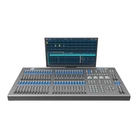
1. HYDRA II AND CONNECTIONS 1.1. HYDRA II FAMILY Hydra II: Natural evolution of Hydra family (Space, Sky & Spirit). Same functionality and enhancement of: control power, control channels, Dmx addresses, and an improved graphical and intuitive user interface. There are four different models: Hydra II S24-3000 24 Submasters, 3 physical DMX outputs, with a total of 6 Ethernet DMX outputs: 1536 directions to control channels and fixture attributes by DMX XLR5 (3 universes). - Page 14 HYDRA II AND CONNECTIONS 1.2. TECHNICAL CHARACTERISTICS 1.2.1. GENERAL CAPACITY & INTERFACES Control channels (maximum) 3000 Models 3072 Configurable as conventional channels or moving 6000 Models 6144 lights parameters. 3000 Models 3 (6) DMX output on XLR5 (on Ethernet) 6000 Models 6 (12) DMX inputs on XLR-5 3000 Models...
-
Page 15: Electric Characteristics
Temperature: -15ºC to 45ºC Humidity: 80% without condensation. 1.3. TECHNICAL SERVICE MADRID/Spain: BEN-RI Electrónica S.A. Pol. Ind. Ventorro del Cano C/. Lozoya Nº 8 28925 Alcorcón, Madrid Tel: 91 472 06 66 You can obtain a updated list of technicals service points in www.lt-light.com... - Page 16 HYDRA II AND CONNECTIONS • Place the console in a plane surface. • Connect the external displays (1 or 2) to the console video outputs (DVI-D Ports, where the lower port is the number 1 and the upper port is the number 2) Console has two DVI-D ports to connect external displays.
-
Page 17: Configuration Of Monitors
HYDRA II AND CONNECTIONS • Set the General Master, GM , at 100% and its key disable (LED off). • Read this user manual. Turn off console switching off console (in the IEC base switch in the rear panel). Note: The shout down process maintains the power supply some seconds before total disconnection. -
Page 18: Configuration Of Language & Keyboard
HYDRA II AND CONNECTIONS Set the touch panel (Generic Non-PnP Monitor, of 800x480) as Main Display and locate it, dragging with the mouse, in the first position and up (front of monitor 1). Apply and close. When displays are configured, start the system from the buttons of the start window: You can start the console with Cold Reset , or not... - Page 19 HYDRA II AND CONNECTIONS Select “Teclados e Idiomas” tab to configure the external keyboard and, if desired, also the system language. Click on to configure keyboard. Select the desired language in: “Apply” the changes. And follow the system instructions to Session Log Off and then, click on Benri to init the session again.
-
Page 20: Connections
HYDRA II AND CONNECTIONS 1.5. CONNECTIONS Main supply: IEC base for 90-260V∼ / 50-60 Hz 2.5A. Always, used normalized cables (confirm the ground plug). The main supply is protected by 2 fuses of 4A, type F. DMX: Dmx-512 outputs with optical isolation. Connectors: Standard XLR-5 female. Dmx-512 input with optical isolation. - Page 21 HYDRA II AND CONNECTIONS External triggers. XLR-4 (female) for 3 external triggers. Code: 1 – Ext-1 2 – Ext-2 3 – Ext-3 4 – 0 V ref. Note: * Ext: Only is necessary to connect the Ext signal with the 0 V ref. signal. Working Lights.
- Page 22 1-10 HYDRA II AND CONNECTIONS IMPORTANT ABOUT ETHERNET Console has 2 Ethernet ports (LAN) of local connection, connect allways the port 2. You can access to these ports configuration from MENU – ETHERNET CONFIGURATION (See Chapter 24). NOTE: ALWAYS CONNECT THE MOUSE OR THE EXTERNAL KEYBOARD WITH CONSOLE TURNNED OFF.
-
Page 23: About This User Manual
2. ABOUT THIS USER MANUAL 2.1. CONVENTIONS Concepts and general functions are identified by their names, as A/B, BANKS… Physical keys are identified as your corresponding icon The action of click over a key, is represented in the same way that the key This icon identified the action of to press and hold down pressed the key This icon identified the action of to release the pressed key This is a key pressed 2 times... -
Page 24: Bank Keys (Touch Panel)
ABOUT THIS USER MANUAL 2.2. BANK KEYS (TOUCH PANEL) Touch panel has 30 soft keys, BANK keys that allow to you to access to macros, groups, positions, colors, etc. This key shows the current configuration. Click here to change the configuration of BANK keys. - Page 25 ABOUT THIS USER MANUAL Example: Select the Patch of Fixtures a) With touch keys *This is the format used in this user manual (more clear) b) With physical keys About a window on touch: Close window Return to the previous window About a window on external display: Close window A lot of menus appear in both, external monitor &...
-
Page 26: Options Windows
ABOUT THIS USER MANUAL 2.4. OPTIONS WINDOWS During the edition process, options windows can be opened (always in a red field on the thouch panel) to help you to complete the edition or command. To select one of these options, you can: •... -
Page 27: Mouse
ABOUT THIS USER MANUAL The fist table column has the main item of the table. This column has cells no editable and indexed. You can use these cells, of the first column, to search. As example in this Cues table, on a cell of first column (cue number), you can enter other cue number, and press to access to this cue. -
Page 28: Colors And Control
ABOUT THIS USER MANUAL 2.9. COLORS AND CONTROL Control source Color Tracking (no control) – Only for attributes Grey Editor (active or selected) Editor (present but not active) Dark Red Submasters Yellow Crossfader or A/B Sequence Cyan for cue on B Dark Cyan for cue on A Inhibited channels &... -
Page 29: System Configuration
3 . SYSTEM CONFIGURATION Hydra II is a configurable system. You can select the number of 3000 Models Submasters, conventional channels and fixture parameters. Addresses 3072 DMX + Ethernet Independently to the number of physical faders, the system can be configured with 24 or 48 masters. -
Page 30: External Displays (Monitors)
SYSTEM CONFIGURATION 3.1. EXTERNAL DISPLAYS (MONITORS) External monitors (1 or 2) shows to you: Status Line, sobre fondo azul, donde vemos el estado general del sistema. • Command line • Configuration buttons for Base Windows. • Base Windows, that are: •... -
Page 31: Configuration Of Base Windows
SYSTEM CONFIGURATION 3.1.1. CONFIGURATION OF BASE WINDOWS Select the Base Windows to show in each external display, using these Configuration buttons: If button is activated (in blue) the monitor shows, respectively: Channels • Fixtures • Submasters • QList Playing (Sequence, Event List or QList/Sub). The selection of the active tab (visualization) •... - Page 32 SYSTEM CONFIGURATION Some windows as well Channels, Fixtures and Free Keys can move and change the display area. Select the desired area by pressing located next to the title of the window. Each time you press this key zone change, between Left, Right and Down. Then to move the window to another position in the same zone, we do dragging from the title, i.e.
-
Page 33: Scrolling
SYSTEM CONFIGURATION 3.2. SCROLLING If a Base Window cannot show all its content, use the window scrolll to paging the content. If the Base Window has no scroll bars, is that alls the contents are visibles. Scroll bars are moved using with the mouse. Set an adecuateed size to each window improvement the console use. -
Page 34: User
SYSTEM CONFIGURATION 3.5. @USER Console has an electronic sheet to write notes (notes for the next shift, reminders, etc). Access to this function clicking: From the external keyboard you have all text editing facilities, including selections with the mouse and the commands to cut (Ctrl + X), paste (Ctrl + V), copy (Ctrl + C) ... -
Page 35: Fixtures Patch
4. FIXTURES PATCH The Fixtures Patch allows to you configuring the type and number of fixtures to control. This configuration is a needed step to work with moving lights. You can control a maximum of 3072/6144 attributes for fixtures (according with model). Remember, you can see/set the number of channels &... -
Page 36: Active Table
FIXTURES PATCH Each Patch line has the configuration about physical moving light (fixture). Each connected fixture must be defined here. Scrollers. It shows if the fixture has a Scroller parameter (color based on gels) External Dimmer. If the fixture has an external dimmer, this is its DMX address. -
Page 37: Quick Edition Of Patch Table (3 Steps)
FIXTURES PATCH 4.1.2. Quick edition of Patch table (3 steps) On Cache table, select the type to insert on patch, in example the 1 MC500(16). Cache list has up to 24 types. Each Cache type shows: Index number - Name – Used Dmx channels Types used on Patch remains marked on Cache with the icon Edit the number of units that you need insert of this type: , and the first DMX address to... -
Page 38: Edition On Patch Table
FIXTURES PATCH 4.1.3. Edition on Patch table Patch table can be edited cell by cell. For this, active the Patch table and move the cursor to the cell for edition (with mouse, arrow keys, etc…) Type: Edit the fixture type entering the index number of desired type as it appears on Cache list. Example: To patch a MC600, enter To patch the same type that the previous fixture, press To delete the complete fixture, press... - Page 39 FIXTURES PATCH Example: In the next example, you can see as a same edition using a group of mc 500 has different outputs on Stage… outputs that depends only of the X/Y Patch of these mac500: Patch Scene output dm: If the fixture has an external dimmer, , here you should edit the DMX address of the dimmer with ddd.l format.
-
Page 40: Scrollers
FIXTURES PATCH sc: If fixture has scroller (color change system based in gels), this cell shows this symbol: This cell editable. edit scroller parameters type, select . More about in the next section. 4.1.4. Scrollers To control Scrollers in a more efficient way, parameters 50: Scroller, these are defined just like a color wheel with its color palettes and steps, but with the particularity of a manual adjustment of steps for each fixture patched in the show. -
Page 41: Loading A New Type To The Cache
FIXTURES PATCH About Types: Name: it allows to you editing a color name for each gel. Palette: it allows to you assigning of a color palette for each color. In this way, Scrollers can have a behaviour similar to other fixtures with Color Wheel (for commands as FIX 1 COL “rojo”) DarkGel: it allows to you indicating that this gel and the next gel are the same “dark”... -
Page 42: The Fixture Definition Information
FIXTURES PATCH Access to the Cache clicking on it or pressing Select the type to be replaced. Access to the Disk table, clicking on it or pressing Search in the directory the type to load Select Disck Select Manufacturer Select fixture model And press If the types-library has not the desired type, the user can edit it. -
Page 43: Editor
5. EDITOR 5.1 CHANNELS Channels are used to control conventional lightings. The number of channels is configured from CONSOLE CONFIGURATION menu (Chapter 3). Channels comply with the principle of HTP/No-Tracking (See below, pag.5-16). 5.1.1 CHANNELS SELECTION From the editor, select a channel, a group or a range, {channels}, with the objective to adjust level at the same time: {channels} Examples... -
Page 44: Level Edition
EDITOR 5.1.2 LEVEL EDITION Before a level will be applied, {level}, it’s needed to have a selection of channels, {channels}, where this level will be applied: Examples {channels} {level} Continuous level, from vertical encoder Set level for cannel 1 from vertical encoder: {channels} Channel 1 at 50%: Channel 1 at 5%:... -
Page 45: Quick Selections
EDITOR 5.1.3 QUICK SELECTIONS Repeat the last selection of channels Selecta ll channels in editor (red & dark red) Select all channels in editor & scene (scene output) Selecta all channels in scene those are inside a range 5.1.4 REMOVING CHANNELS Selected channels, {channels}, can be removed from the editor Remove channels fading during 2 sec: Example –... -
Page 46: Invert Function
EDITOR • Channel number. • Current level (numeric & graphic information) • Frame. Color code e information about “current level”: Not-used channel, at 0%. This channel isn’t controlled. Grey Level of selected channel. When a channel is selected, its {level} can be edited using any explained method. -
Page 47: Fixtures
EDITOR 5.2 FIXTURES Fixtures are used to control moving lights, LED lights, color changers, smoke machines, media servers, etc… The console, by default, hasn’t assigned fixtures. First step is to set the fixtures to use or edit the patch of fixtures from (Please, see chapter 4 –... -
Page 48: Parameters
EDITOR A selected parameter can be edited at any moment! A present parameter is in editor, but can be edited; it proceeds from previous selections and also is included in cues & groups. Each table cell has information about a parameter. In general: Color 1 is the parameter name The color rectangle, %, close the value, shows the control source of the parameter... -
Page 49: Quick Selections
EDITOR Examples {fixtures} Fixture 5: Fixtures 1, 45 & 58: Fixtures 1, 54 & 58: Trick - Use as “plus” key Fixtures from 5 to 15: Fixtures from 5 to 15 & from 54 to 58: Trick – From the entered fixture number to the last fixture: Fixtures 1 to 15 except the 5: Fixtures 1 to 15 except the5 &... -
Page 50: Selections From External Display
EDITOR Examples {fixtures} {level} Continuous level moving the vertical encoder Continuous level for channel 1: {fixtures} Fixture 1 at 50%: Level from 00% to 99% Fixture 1 at 5%: {fixtures} Trick - Use to repeat the last level assigned by numeric pad. (2 digits, from 00 to 99) Fixture 1 at 25% &... -
Page 51: Editing The Parameters X & Y
EDITOR 5.2.6 EDITING THE PARAMETERS X & Y Only for fixtures with position parameters X & Y- Select the fixtures {fixtures}, and edit the position: {fixtures} Edit position (X/Y) for fixture 1: More about trackball in TRACKBALL page- 5-15 The parameters X/Y have a Home value associated of 50%, obtained a zenithal position for the fixture. 5.2.7 EDITING FROM THE HORIZONTAL ENCODERS , its associated parameter is edited. - Page 52 5-10 EDITOR 5.2.7.1 SPECIAL CONTROL ABOUT HORIZONTAL ENCODERS - When WHEEL mode is active, it’s possible to use the arrow keys to edit parameters and channels in small increments. Active (LED on). In this mode: Increment/decrement a %, or a parameter step. Only with fixtures selection, select previous/next parameter.
-
Page 53: Editing Any Parameter
EDITOR 5-11 5.2.8 EDITING ANY PARAMETER To edit a parameter of one or several fixtures, first, select it pressing: {fixtures} {Choose a Parameter} {Choose its Value (%)*} Over this edition window is possible to edit the parameter, directly, entering its value (or clicking on it) Value (%)* toggles the edition window scale between 0-100(%) &... -
Page 54: Editing With Palettes
5-12 EDITOR 5.2.10 EDITING WITH PALETTES Some parameters can be edited using palettes in accordance with their category. Palettes are accessible from touch panel. To this title, please, configure BANKS in AUTO mode (default mode), pressing: Remember, console has a key per each category. The next commands can be executed for any category, even thought the next examples are done for color category: {fixtures} {choose palette clicking on touch}... - Page 55 EDITOR 5-13 Select all parameters of a category, in example, the color {fixtures} parameters (in scene) into the editor for the selected fixtures Select all parameters of the fixtures {fixtures} Release of the editor all parameters of a category, in example, {fixtures} release all color parameters of the selected fixtures Release of the editor the selected fixtures...
-
Page 56: The Invert Function
5-14 EDITOR 5.2.12 THE INVERT FUNCTION Active selection (in red) is created by the channels & fixtures ready to be edited. When beginning a new selection, the previous selection passes to present (in dark red). Present channels & fixture parameters are in the editor, but they are not ready to edit them. -
Page 57: Trackball
EDITOR 5-15 5.3 TRACKBALL The functions that are associated to the TrackBall: sets the sensibility of TrackBall and encoders. Press as many times as necessary to set the sensibility: Sensibility FINE LED Comments Normal High For change a value will be needed a large displacement of the TrackBall, or the control wheels, obtaining a better precision. -
Page 58: Bank Keys On Touch Panel
5-16 EDITOR allows to edition in relative mode of parameters X/Y in a selection of several fixtures. Press many times as needed to set the mode: FAN LED Mode/Comments Normal. Desactive Fan. X/Y values are not affected by the fan. Example - Increase of Y of the fixtures 1 to 8 Lineal Fan. -
Page 59: Live.t, Fadding From Editor
EDITOR 5-17 Some examples of use, in relation to channels & fixtures, using Bank keys in mode Select channels 1, 12 & 27 and edit them at 100% of level. Select fixtures 1 & 13, edit them at 100% of level & at Pink+ color Call channels 1, 12 &... -
Page 60: Control For Live.t (C3)
5-18 EDITOR Control for Live.T (C3) As default, and always after a cold reset, C3 special fader is set as control for Live.T of C3 allows to you C3 fader, with scale from 0 to 200%, helps Value of the resulting time or activating/deactivating applied time in live fades. - Page 61 EDITOR 5-19 APPLYING PALETTES IN THE EDITOR Using these commands, values of palettes (in the examples of Color) are applied in the editor with a fade of the resulting time of Live.T In this way you can apply colors, positions, etc, in live, using fades with a time that now you can change in a simple way: LT recommend, always that possible, to use the direct access of the screen to apply libraries* &...
-
Page 62: Htp Mode & No-Tracking
5-20 EDITOR 5.6 HTP MODE & NO-TRACKING HTP mode: The channel takes the higher level among the playbacks that are controlling it. In other words, the playback that has the higher level is the playback that controls the channel. As exception: Always that a channel (or dimmer parameter) is controlled from the Stage editor, this editor has the control about it. -
Page 63: Editor Configurations
EDITOR 5-21 5.9 EDITOR CONFIGURATIONS … Each item is selected with its item key and its number, in example The command line shows us the item of the last selection. These item can be channel>, fixture>, group> or cue>. In example, if the command line shows fixture>, for select the fixture 58, you can press instead of , instead of The command line collects the keys pressed (the command), and it starts with each new command. -
Page 64: Modes For Channels Window (Monitor)
5-22 EDITOR 5.11 MODES FOR CHANNELS WINDOW (monitor) There are three visualization options, placed in the window title, and that the user can select using the mouse: If actives, shows all channels, that are configured in the system, in ascendant order. - Page 65 EDITOR 5-23 Active It’s possible to move the channels to place them in any location into the channels window. This ability is very used to locate the channels in conceptual groups (colors, functions, etc) … And also in geographical mode, imiting the phisical location. Selection and movement of channles is done using the mouse, clicking to select/unselect and draging to move them.
- Page 66 5-24 EDITOR HYDRA II – LT LIGHT...
-
Page 67: Cues & Groups
6. CUES & GROUPS Hydra II records in cues & groups only the items that are in the editor at the moment of recording. The channels & fixture parameters that are in editor are showed in red or dark red. Cues are numbered from 1 to 2000, and they admit decimal numbers, in example, 55.5, 1.9, etc. -
Page 68: Recording Groups
CUES & GROUPS 6.2 RECORDING GROUPS First step to create a group is to select channels and fixtures that will be inside it, {channels, fixtures}. The edition the selected channels & fixtures is optionally. Channels & fixtures didn’t edit are recorded at 100% of intensity. -
Page 69: Group Opction
CUES & GROUPS 6.2.3 GROUP OPCTION After group recording, using any of the previous methods, OPTIONS window for this group is presented, temporally, in the touch panel. From this window, if desired, you can edit the times & text that are associated to this new group. -
Page 70: Options For All Cues & Groups
CUES & GROUPS With OPTIONS opened, it’s possible: • Press and return to editor. • Press and load this cue in the Submaster • Press and load it in A/B You can return to this window, at any time, pressing 6.4 OPTIONS FOR ALL CUES &... -
Page 71: Selecting Cues/Grupos In The Editor
CUES & GROUPS 6.5 SELECTING CUES/GRUPOS IN THE EDITOR Any recorded cue/group can be used in the editor for new editions. Examples with Cue 10: Select in the editor the channels & fixtures inside Cue 10. Only items, no level or values. -
Page 72: The Scene
CUES & GROUPS Select the color parameters of the fixture 8, as they are inside the cue 1: Select the Iris parameter of the fixture 8, as it is inside the cue 1: {Select parameter} Selecta all fixtures as they are inside cue 1: 6.6 THE SCENE The scene, {scene}, is composed for the contents of the editor, and for the outputs of Submasters... -
Page 73: Exam Of Cues & Groups
CUES & GROUPS Preselect the items of the scene output of one or several Submasters to the editor: … ... (as many Submaster selection keys as desired) this symbol indicates that the key is pressed and held down pressed, and this, that the key is released Preselect the items of the scene output of the Sequence A/B to the editor: 6.6.3 EXAM OF CUES &... -
Page 74: Deleting Cues/Groups
CUES & GROUPS 6.6.4 DELETING CUES/GROUPS to delete a cue to delete a group to delete a cues range to delete a groups range **Console requires to you confirmation to delete all console cues!!!! to delete all console groups!!!! 6.6.5 MODIFYING A CUE/GROUP Press to set the desired editor to do the modification:... - Page 75 CUES & GROUPS The status line shows the flag of the modification: The first cue/group of the range is called to the editor with a fade. The modifications, {modifications}, are done over this first cue/group, adding, editing, and/or releasing items. After modifications, to record them, .
- Page 76 6-10 CUES & GROUPS 6.6.6.2 ATRIBUTTES OPTIONS (All Examples in Absolute/Absolute mode) It’s the attribute to apply the modifications only if the item (channel or parameter) was already in the cue. Example: {Channel 1 @ 60, Channel 2 @ 50} Inside source cues Inside modified cues Channel 1@ 50, Channel 2 @ 30...
-
Page 77: Copying Cues/Groups
CUES & GROUPS 6-11 6.6.7 COPYING CUES/GROUPS When a group/cue is copied, all contents and attributes are copied (text, times…) Copy the Cue Nº in the Cue Nº Copy the Group Nº in the Group Nº Copy a Cues range in other one: Copy a Groups range in other one: Examples –... -
Page 78: Times
6-12 CUES & GROUPS 6.7 TIMES T(In) Input time. It’s the time that the cue/group uses to fade from 0% to 100%. T(Out) Output time. It’s the time that the cue/group uses to fade from 100% to 0%. **When cues are played in lists (Sequence), the output times are applied to the scene cue. T(Auto) Auto time (also named delay time). -
Page 79: Timing
CUES & GROUPS 6-13 Use the arrow keys (or mouse) to move the selected cell. If you need modify a default value of an New values are entered from the numeric pad (or external option of the user setup, keyboard) and the edited values are validated with To close this window, press ** Check that the functions related to the arrow keys You can access to this menu clicking... - Page 80 6-14 CUES & GROUPS There are 6 timings in For all these timings: HPTs (channels & dimmers) fade in, from 00 to FF. This will be equivalent to the notation HTP 00-FF. Shapes fade in, from 00 to FF, for their parameters of Size & Rate. This will be equivalent to the notation Shape 00-FF All the contents of the cue/group start a fade at the beginning (00) and end it the end (FF) of the input process.
-
Page 81: Set The Default Timing
CUES & GROUPS 6-15 Channles, dimmers, and the parameters of X, Y, COL and BEAM, start a fade at the beginning (00) and end it the end (FF) of the input process. The rest of LTP parameters start and end at the same time (Begin=End=FF) at the end of the process, in mode that changes as color, gobo, etc, will be done suddenly but at the end of the process. -
Page 82: Time Parts For Cues
6-16 CUES & GROUPS 6.9 TIME PARTS FOR CUES One cue can have 9 parts in addition to the base cue. Each part can have its contents and its times, T(In) and T(Wait In) that are the times that define the input process. Program parts to a cue to obtain that the item of a cue can have different input process, like a timing but absolutely free of contents for each part. -
Page 83: Returning A Item Of A Part To The Base Cue
CUES & GROUPS 6-17 6.9.2 RETURNING A ITEM OF A PART TO THE BASE CUE Return an item of a part to the base cue is the same that move the item to the part 0: {item selection} Example- Modify the cue 10 to move the channel 12 to the part 0 (base cue): 6.9.3 EDITING TIMES FOR THE PARTS Each part can have its T(In) and its T(Wait In), and this times are edited at the same way that the other times... -
Page 84: Live.t For Cues & Groups
6-18 CUES & GROUPS 6.10 LIVE.T FOR CUES & GROUPS (live-time) function allows to you applying of a time in “live” for the editor selections. Live.T is the time used from editor in live editions. Its value is showed in the status line, and is controlled using C3 special fader. -
Page 85: Applying Live.t
CUES & GROUPS 6-19 you access to the configuration screen (Menu/User Setup/Playbacks) of these Note: Pressing its special faders (C1..C3). From this menu you can change this control from C3 to C2 or C1, you can delete it… More information in Chapter 14 Applying Live.T When Live.T function is enabled, its time is applied as fade time for the fades of the editor. - Page 86 6-20 CUES & GROUPS HYDRA II – LT LIGHT...
-
Page 87: Libraries
7. LIBRARIES The libraries are a powerful edition tool. A library has concrete data to be used in the creation of scenes and modifications. Libraries are very used for “positions” because they provide to you great facilities and a fast process to modifications. -
Page 88: Position Libraries (Positions)
LIBRARIES 7.2 POSITION LIBRARIES (POSITIONS) Position libraries are used to record the positions more used in a show. Positions are edited from the editor, with values for the position parameters (X/Y) of any fixture to include in the library. Each position can have one, several or all fixtures. A position only can be applied over fixtures that they are included in it. -
Page 89: Libraries Of Dim Or "Scenes
LIBRARIES 7.4 LIBRARIES OF DIM OR “SCENES” DIM libraries or scenes admit any channel or parameter inside. Scenes allow to you recording a scene as a whole, including one, several or all channels/parameters. Scenes are libraries of complex combinations (in example, “sunset scene”... -
Page 90: Libraries List
LIBRARIES 7.6 LIBRARIES LIST Each library can have an associated text that also can be edited from the library list (there is a list per category). Example for positions: {Text} 7.7 MODIFYING A LIBRARY When a library is modified, this modification is reflected in all the cues/groups where is used. This property does of the libraries the powerful tool for modifications. -
Page 91: Fade-Time For Palettes & Libraries: Live.t
LIBRARIES It’s possible to change the fixtures selection as many {fixtures} , {fixtures} times as necessary to create the desired picture … Remember, as exception, DIM libraries can be applied {channels} over a channels selection. *** The application of libraries can be combined with any other edition method: using palettes, using encoders or numeric edition, etc. -
Page 92: Applying Live.t
LIBRARIES About fader: When fader is in its middle point, time is at 100% When fader is in its downer extreme, time is at 0% When fader is in its upper extreme, time is at 200% *Previous examples are based in a Live.T of 4.5s, you access to the configuration screen (Menu/User Setup/Playbacks) of these Note: Pressing its special faders (C1..C3). -
Page 93: Other Commands
LIBRARIES 7.9 OTHER COMMANDS 7.9.1 EXAMINING LIBRARIES To exam the list of all libraries of a category (in example, positions), press: To exam the contents of a concrete library (in example, one position), press: 7.9.2 DELETING LIBRARIES To delete a library (in example, a position) press: To delete a range of libraries (in example, positions range), press: To delete all libraries of a category (in example, all positions), press: HYDRA II –... -
Page 94: Appendix - Libraries, Palettes
LIBRARIES 7.10 Appendix - LIBRARIES, PALETTES… Category About Library These libraries are recorded by fixture. Only admit position parameters defined as L = p in its fixture profile These libraries are recorded by item (channel and fixture) including the whole scene. Admit all parameters &... - Page 95 LIBRARIES All libraries are affected by the menu option: Library Rec Mode that you can find it inside of Category About Palette Only is applied to the parameters of type 0:X and 1:Y Only is applied to the parameters of type 20:DIMMER, 21:SHUTTER & 22:STROBO Only is applied to the parameters of type 40:Cyan, 41:Magenta, 42:Yellow, etc.
- Page 96 7-10 LIBRARIES HYDRA II – LT LIGHT...
-
Page 97: Submasters
8. SUBMASTERS 8.1 SUBMASTERS Hydra II has 24 or 48 Submasters (model S24 or S48). A Submaster is a playback that can play: A Groups • A Cue • A Cues list (Chapter 10) • An Effect (Chapter 9) • A Channel •... -
Page 98: Loading Cues
SUBMASTERS 8.1.2 LOADING CUES To load a cue in a Submaster, press Example- Load the cue 5 in a Submaster: To load a cues list only in one Submaster (as list), press: Example – Load the list of cues from 1 to 5 in one Submaster: To load a cues range in consecutive Submasters, one cue per Submaster, press: Example –... -
Page 99: Loading Channels
SUBMASTERS 8.1.3 LOADING CHANNELS The Submasters admit individual channels, as channels, no as groups. To load a channel in a Submaster, press: To load a range or collection of channels in consecutive Submasters: 8.1.4 LOADING CONTROLS OF RATE & LEVEL It’s possible to configure a Submaster as RATE control or LEVEL control for the Sequence A/B and/or a Submasters range. -
Page 100: About Ranges
SUBMASTERS 8.1.6 ABOUT RANGES… A range is defined using 2 numbers, its first item & its last item (from nº to nº): If last number of range is omitted, it is the same that entering the number of “last recorded/configured item”... -
Page 101: Modes For Cues & Groups
SUBMASTERS 8.1.8 MODES FOR CUES & GROUPS A group/cue can be loaded in a Submaster in the next modes: Normal Normal Submaster controls the output level of its cue/group to scene. The Submaster output is added to the scene. Inhibit Inhibit Submaster prevents the scene output of the HTP items inside its cue/group. -
Page 102: The Submasters Window On Ext Displays
SUBMASTERS 8.1.9 THE SUBMASTERS WINDOW ON EXT DISPLAYS The Status line of the Submaster window shows to us the general flags about Submasters, from left to right: Configuration about C1 , by default, the control masters of all the Submasters. If the configuration •... -
Page 103: Emptying Submasters
SUBMASTERS When a channel/parameter is been controlled from a Submaster, you can see it in yellow (example channel 3). As exception, the inhibited channels/parameters that you can see the inhibit effect in black (example channel 4). 8.1.10 EMPTYING SUBMASTERS Empty one or several Submasters: Empty all the Submasters: 8.1.11 EXAMINING SUBMASTERS &... - Page 104 SUBMASTERS About these screens: allows to you toggling between the modes of exam & modify. In exam mode it’s not possible to modify data. , to edit a Submaster the first step is Inside screens of modification as select this Submaster, clicking with mouse or pressing .
- Page 105 SUBMASTERS In case of Submasters for Rate, Level, Rate Shape and Size Shape the range of Submasters that are controlled by this, is edited in the third cell, with the format To edit it, enter the numbers of first and last Submaster of the range. In this way: •...
-
Page 106: Playing Back From The Submasters
8-10 SUBMASTERS PLAYING BACK FROM THE SUBMASTERS LED off its Submaster is empty LED on its Submaster is loaded with a Channel, Group or Cue A Submaster loaded with a channel, group or cue, it can play back its content in one of these modes: •... - Page 107 SUBMASTERS 8-11 To take the control manually, at any time, move its fader to arrive at its level of current output (graphics bar yellow & grey to the same point). When this point is arrived, the console emits a “BEEP”. The Submaster control is manual.
-
Page 108: Flash Play Back
8-12 SUBMASTERS and to seelct the Submaster that you want to put with highest priority. You can select this Submaster directly over the list in the tocuh (where active Submasters are sorted in by priority, from high to low, touching on which you place first) or pressing the Submaster selection key. - Page 109 SUBMASTERS 8-13 It’s possible to set an output level for Flash, different that 100% 8.2.3.2 SOLO To activate the Submaster at 100% at the same time that to force the rest of Submaster outputs to zero, in SOLO mode, press and hold down pressed its Release for deactivate the Submaster &...
-
Page 110: Modifying Submasters
8-14 SUBMASTERS 8.3 MODIFYING SUBMASTERS The modification of a cue or group loaded in a Submaster can be done directly over the Submaster: {Modify in the editor} You can use this method independently of the output level of the Submaster (including at its 0%). If the Submaster is at 100% or 0% the modifications will be done with the absolute values, but if the Submaster is not at 100% or 0% the modifications will be done relatively. -
Page 111: Pages
SUBMASTERS 8-15 8.5 PAGES Each one the 2000 pages can store the content of all the Submasters & the Sequence A/B. All content stored in a page are recovered at the same time, as block. Pages are an efficient tool to organize the information for the playback process. -
Page 112: Loading Pages In Submasters
8-16 SUBMASTERS 8.5.5 LOADING PAGES IN SUBMASTERS There are 2 modes to recover a page only in the Subamasters: Comment Mode Command Only the Submasters that have contents inside page are loaded with the no-forced new content. (normal) All the Submasters are updates. The Submaster that has contents inside page are updates with the new content. -
Page 113: Functions About The Current Page (Active)
SUBMASTERS 8-17 8.5.9 FUNCTIONS ABOUT THE CURRENT PAGE (ACTIVE) {exam contents} Exam: {modify contents} Modify: Empty: 8.5.10 MORE FUNTIONS FOR PAGES 8.5.10.1 MODIFICATION To edit the contents in Submasters and Sequencer of a Page, press: {Modifications} 8.5.10.2 COPY & EXCHANGE To copy a page or range, press: Example - Copy pages from 1 to 5, in pages from 10 to 15: To exchange 2 pages or ranges, press:... -
Page 114: Submasters & Mouse (Screen)
8-18 SUBMASTERS 8.6 SUBMASTERS & MOUSE (SCREEN) Mouse click on the Submaster number/title zone is the same that to press on Submaster selection key: Mouse click on the Submaster output level (number) is the same that to press on the Submaster execution key: Mouse scroll moving over the zone of the level graphic is the same that to move the Submaster fader. -
Page 115: Effects
9. EFFECTS Hydra II has 2000 Effects (Chases) and can playback, at the same S48 MODELS time a maximum of 48 or 24 (depending of the model). Maximum of 48 effects in playback An effect is created inserting cues, groups or channels. The effects S24 MODELS are executed in Submasters. -
Page 116: Parameters Definition (1)
EFFECTS 9.1.1 PARAMETERS DEFINITION (1) It’s the number of the effect that you are editing. This number identify to the effect. It defines the effect type. It indicates the content of its steps, in other words; if the step has a cue, a channel, or a group. All the steps in an effect are the same type. After type is selected, the items list shows all the possible items to insert as steps. - Page 117 EFFECTS It’s the effect direction, the order of secession of the steps in scene: UP - Ascendant (1, 2, 3...8, 9) DOWN - Descendant (9, 8, 7... 2, 1) CYCLIC - Cyclic (1, 2, 3... 8, 9, 9, 8, 7..., 2, 1) It’s the step attribute, the mode that the steps use to out to scene: HARD Each step is activated and deactivated without fade.
- Page 118 EFFECTS Direction DOWN Direction CYCLIC It’s the base cue that is activated or deactivated at the same time that the effect and it is used as static part of the effect. These data are only informative data. The first one is the number of the total steps of the effect (on STEPS LIST).
-
Page 119: Steps Edition, The Lists Of Steps & Items (2, 3)
EFFECTS 9.1.2 STEPS EDITION, THE LISTS OF STEPS & ITEMS (2, 3) When the contents of the effect (CHANNELS; GROUPS or CUES) are configured, you can edit the STEPS LIST. The list of available items (about the selected contents), now, it’s showed on ITEMS Steps are inserted starting from the cursor position. -
Page 120: Some Tricks About Effects Edition
EFFECTS Press and return to editor. Press , and load it in a Submaster You can return to this window, at any time, pressing 9.1.4 Some tricks about effects edition In ITEMS list, select using the mouse all desired items & in the desired order, considering that to select a range must be pressed (on external keyboard), and to select several not consecutive items,... -
Page 121: Modifying An Effect
EFFECTS 9.2 MODIFYING AN EFFECT To modify an effect, open its edition table with one of these commands: {Effect modification} {Effect modification} If the effect is loaded in a Submaster, you can use also this: {Effect modification} Effect data can be modified including when the effect is active. 9.3 MODIFYING EFFECT PARAMETERS Open the effect list to modify any effect parameter (text, Step Time, etc): {Parameters modification}... -
Page 122: Exchanging
EFFECTS 9.6 EXCHANGING It’s possible to exchange an effect or a range, respectively: Example - Exchange the contents of the Effects 1 & 5: If the effect 5 is not stored, after exchange, the effect 1 will be not stored. 9.7 DELETING EFFECTS An effect: A range:... -
Page 123: The Effects Playback
EFFECTS 9.8 THE EFFECTS PLAYBACK The effects are played back in the Submaster. Each effect uses one Submaster for its playback. An effect Submaster has: • Its selection key (grey) • Its playback key (blue) • Its control fader (for Rate or Level control) 9.8.1 LOADING To load an effect in a Submaster, in mode EFFECT Rate (with rate control), press:... -
Page 124: Loading Effects From Bank Keys
9-10 EFFECTS An effect is loaded as inactive and with its rate control (Rate) or level control (Level) set at 100%, ready to be played back without the need to move its fader. Note that the rate control faders are in blue and they have the 100% point in the middle of its travel (available to accelerate or decelerate). -
Page 125: Emptying
EFFECTS 9-11 9.8.3 EMPTYING Commands to empty the Submasters: Empty one Submaster Empty several Submasters Empty all Submasters 9.8.4 PLAYING BACK An effect is played back in a Submaster. The effect is loaded as inactive and with its rate control (RATE) or level control (LEVEL) set its 100%. -
Page 126: Others Functions
9-12 EFFECTS EFFECT Level The effect fader that is loaded as controls the output level of the effect (for dimmers and channels). When an effect is loaded this master is locked at 100% (Full); to take control it’s needed to move it up to the upper extreme. -
Page 127: Learn Time Function
EFFECTS 9-13 9.9 LEARN TIME FUNCTION Access to the learn time functions pressing (Learn Time) Learning the StepTime for an effect: It is possible to learn the StepTime of an effect, its rhythm, from a playback in manual mode. This function is very used to synchronize an effect rhythm with a song, etc. For this, load the effect to synchronize in a Submaster and: •... - Page 128 9-14 EFFECTS HYDRA II – LT LIGHT...
-
Page 129: Sequences
10. SEQUENCES Hydra II executes lists of cues on any of its Playbacks, as any Submasters and the S24 - models A/B Sequence Up to 25 simultaneous sequences A list of cues plays back its cues, one by one, in order, by crossfades. A crossfade is a double fading between 2 cues, one of them fade-out of scene (cue in stage /A) S48 - models and the other fade-in scene, (next cue /B). -
Page 130: Loading In A Submaster
10-2 SEQUENCES 10.1.2 LOADING IN A SUBMASTER Load a range of cues as a list of cues closed: About range of cues: Each range is defined with 2 numbers (first cue & last cue). If the first cue is omitted, console will take the first console cue. -
Page 131: Opened List & Closed List
SEQUENCES 10-3 10.1.3 OPENED LIST & CLOSED LIST Opened list: Closed list: It’s a list where new cues are added. It’s a list where only the new cues inside the loaded range are included. 10.2 PLAYING BACK A QLIST A QList can be executed (by crossfades) in the modes manual & automatic (temporizing with the program times). -
Page 132: Automatic Playback
10-4 SEQUENCES 10.2.2 AUTOMATIC PLAYBACK Each GO starts a new crossfade, even if the previous one is not finished. Fade times of the next cue, T(In) and T(Out), control the double fade. Wait times of the next cue, T(Wait In) and T(Wait Out) control the starting of each fade. - Page 133 SEQUENCES 10-5 10.2.2.2 A SUBMASTER Start a new crossfade in automatic mode pressing • Its LED blinks during the crossfade. If cue in B has T(Auto), at the end of the current crossfade, T(Auto) is computed as a time of wait between two crossfades.
-
Page 134: Priority Control
10-6 SEQUENCES The graphic bars that show the progress of the current crossfade have the next color code: A/B Sequence QList / Sub Both T(In) T(Out) T(In) T(Out) T(Auto) T(Wait In) T(Wait Out) Cyan Dark Cyan Yellow Light Yellow Dark Blue Dark Grey Grey 10.2.3... -
Page 135: Crossfade Dipless
SEQUENCES 10-7 10.3.1 Crossfade Dipless A Dipless crossfade is a crossfade where, the channels/dimmers shared by A and B never reach a level smaller than the level of the cue in B (next cue). About dipless crossfade, for all console crossfades, the console can use one of these two methods: T-IN: Channels/Dimmers, of the cue in B, fade from its level in A (scene) to its level in B (target) in T(In) seconds. -
Page 136: Manual Displacement
10-8 SEQUENCES 10.4.1.1 JUMP CONTROL FOR A/B SEQUENCER allows to you controlling of the programmed Jumps that have a Loop. When one of these Jumps is been played back, the LED is on and it’s possible: To avoid that the Jump will be executed more times, its Loop value is forced to 0. Press To force a displacement to the next cue out of the Jump. -
Page 137: Rate Control
SEQUENCES 10-9 10.5 RATE CONTROL 10.5.1 FOR A/B SEQUENCER 10.5.1.1 RATE FUNCTION Crossfade times can be controlled pressing . When is active (its LED lits), you can: Control the crossfade times moving the last horizontal encoder, Rate A/B Rate value is showed in percent (%) in the status line of the Sequence window. This value appears in red when is different to 100% (programmed times). -
Page 138: Move In Black Function
10-10 SEQUENCES Each cue can have one command that is programmed form the cue list. Access to the cue list pressing . For any Command cell: Select NONE to empty the associated command. Select MACRO to associate a recorded MACRO as command. Select PORT A(RS232) to associate a A-232 command as cue command. -
Page 139: Can I Disable The Mib Function Of A Particular Cue
SEQUENCES 10-11 screen, the MIB data are showed in the cell of each available cue fot MIB, and this cell contents the cue from which MIB is executed: ••• In the example, fixtures parameters of cue 4 that satisfy the MIB conditions, they change at cue 2 crossfade. 10.8.1 Can I disable the MIB function of a particular cue? Yes, setting its... -
Page 140: Mdfy Mdfy Function -A/B Sequencer
10-12 SEQUENCES When playing the sequence or a cue list a MIB is in execution, if you run the GO of the MIB cue before the MIB end, the MIB changes immediately take their final values. In example: There are 4 cues: 1, 2, 3 & 4. Cue 1 has fixtures 1 -10 activated in red. -
Page 141: Crossfade Output
SEQUENCES 10-13 10.10 CROSSFADE OUTPUT The commands to capture the crossfade output (items and values) or to select the items (only items, no values) of the crossfade output are: Select the items of the crossfade output of the A/B Sequencer pressing Select the items of the crossfade output of a Submaster pressing Capture the output of the crossfade output of the A/B Sequencer pressing Capture the output of the crossfade output of a Submaster pressing... - Page 142 10-14 SEQUENCES Examples – Cues 1 and 2 are programmed with the next times: Total time 6.5 sec (2,5+3+1) 6.5 sec (3+3+0,5) Editing in normal mode T(In): Total time in the Total time input process = 5,5 sec (1,5+3+1) 6,5 sec (3+3+0,5) T(In) + T(Auto) + Editing T(In) with the learn time function active: T(Wait In)
-
Page 143: Macros
11. MACROS Hydra II has 2000 macros. A macro has several keys programmed by the user that can execute at any moment: 1. Accepts any pressed physical key and some soft key*. 2. Doesn’t accept movements of faders, wheels, joystick or trackball. 3. -
Page 144: Modifying A Macro
11-2 MACROS Example: Record the macro 1 that selects the channels from 1 to 5, from 10 to 17 and 68. {text} Bank keys are configured clicking on , that can be configured as (fixed access to macros) or as (interactive access to macros each time that is pressed). -
Page 145: Examining A Macro
MACROS 11-3 allows to you insert a key that only is “pressed” allows to you insert a key that only is “released” The 2 last options are used to execute flash functions. The macros don’t record the duration or time. For these cases, it’s possible to use 2 macros, one to activate the flash function and other to deactivate it. -
Page 146: Playback
11-4 MACROS To exchange 2 macros or ranges, press: Examples: 11.6 PLAYBACK A macro can be executed using one of these methods: • From the editor • As command of a cue, when the cue is executed in A/B sequencer or a QList. •... -
Page 147: From The Event List
MACROS 11-5 In this way is very easy to synchronize any playback action with the Sequence: Load a page, play back a effect, etc. 11.6.3 FROM THE EVENT LIST A macro also can be executed as an event, from the event list. Event list is programmed inside Multimedia/Time Code menu Selecting the Event Play as And then;... -
Page 148: Soft Keys
11-6 MACROS 11.8 SOFT KEYS Soft Keys stored in macros, now, they are: Executing of A/B Seq from monitor Executing of QList on Submasters from monitor Control of Event List in INTERNAL mode and control about activating of the TC & mode Control of MIDI mode/port Bank keys as direct access to palettes &... -
Page 149: Bank Keys & General Functions
12. BANK KEYS & GENERAL FUNCTIONS 12.1 BANK KEYS ON TOUCH PANEL Touch panel has 30 soft keys, BANK keys that allow to you to access to macros, groups, positions, colors, etc. Touch panel also shows menus and This key shows the current other screens…... -
Page 150: Fixed Modes
12-2 BANK KEYS & GENERAL FUNCTIONS 12.1.1 FIXED MODES When you press.. What happen? Mode of BANK keys Corresponding macro is executed. BANK keys are direct MACRO Nº OK accesses of macros. Corresponding page is loaded on the BANK keys are direct Submasters. - Page 151 BANK KEYS & GENERAL FUNCTIONS 12-3 LEE, ROSCO, ETC REFERENCES – AMPLIATION OF COLOR PALETTES New color palettes have been added; palettes of references as Lee, Rosco… You can access to these data base of colors from the BANK keys, using the modes and/or , in the second page, 2/2, you find the access to these data When you access to the color palettes,...
-
Page 152: Auto Mode
12-4 BANK KEYS & GENERAL FUNCTIONS 12.1.2 AUTO MODE This mode is a combination of the previous fixed modes, and these modes are selected automatically each time that the user press one of these keys: MACRO ( ), PAGE ( ), CH ( ), FXT ( GRP (... - Page 153 BANK KEYS & GENERAL FUNCTIONS 12-5 Step 1 & 2 – They allow to you selecting of the item for the key: Selecting the item type and…. Its number Step 3 – It allows to you configuration of options about the selected item.
- Page 154 12-6 BANK KEYS & GENERAL FUNCTIONS that the effect is selected from this key. Check this box if you want the system uses the previous Submaster only if it’s inactive. If not, console answers to you about it. Check this box if you want the system does a GO of the effect in the same moment of the load, automatic GO.
-
Page 155: Bank Keys In An External Monitor
BANK KEYS & GENERAL FUNCTIONS 12-7 12.1.4 BANK KEYS IN AN EXTERNAL MONITOR This option (improved with an external & touch monitor) gives to you a really useful selection window, quick and intuitive for items selections from the external monitor. You can open/close this window clicking on its access button: You can select any item of this window, Free Keys, using the mouse, if the external monitor has touch, you can select any item directly with your fingers. - Page 156 12-8 BANK KEYS & GENERAL FUNCTIONS You can move it to any horizontal position (dragging): ó You can move it to the same position that other window (i.e. channels). Selection tabs appears: Drag and Drop is a precision movement and may require some practice. If a window is seen badly, it will be enough deactivate it &...
-
Page 157: Selecting Ranges
BANK KEYS & GENERAL FUNCTIONS 12-9 12.2 SELECTING RANGES - A range of items is defined with , where: Nº is the number of first item of the range is the number of the last item of the range It’s possible to select ranges of: Channels, fixtures, groups, cues, effects, pages, macros, positions, dimmers, colors, gobos, etc. -
Page 158: Release
12-10 BANK KEYS & GENERAL FUNCTIONS Exchange the groups Nº & N Exchange the cues Nº & N Pages: Copy the page Nº in the page N Exchange the pages Nº & N Effects: Copy the effect Nº in the effect N Exchange the effects Nº... -
Page 159: Ok & Call
BANK KEYS & GENERAL FUNCTIONS 12-11 All parameters of a category (i.e. all color parameters): Contents of a cue or cues range: Contents of a group or groups range: Contents of a part of a cue: The LTP parameters pass to tracking mode suddenly. The channels &... -
Page 160: Mdfy & Exam
12-12 BANK KEYS & GENERAL FUNCTIONS Cue Parts: The contents of the part Nº of the cue Nº are pre-selected in the editor The part Nº of the cue Nº is entered in the editor at 100%, fading in 2 sec. - Page 161 BANK KEYS & GENERAL FUNCTIONS 12-13 … … Exam of contents of a cue/group/library: Inside these screens, it’s possible to go to the modification of item in exam, pressing Modification of contents, in editor, of a cue/group/library: {Modify} {Modify} {Modify} Modification of contents, in editor, of a range of cues/groups: {Modify} {Modify}...
-
Page 162: Next Item
12-14 BANK KEYS & GENERAL FUNCTIONS Exam of all Submasters (current contents): Modification of all Submasters (current contents): Exam of the show data: Special function: For modifications of the cue in A of the A/B Sequencer (See chapter 10). {Editor} 12.7 NEXT ITEM allows to you searching the next channel, fixture, group, cue... -
Page 163: Previous Item
BANK KEYS & GENERAL FUNCTIONS 12-15 b) Restricted mode. It increments the number of the channel or fixture of items inside editor. Selection In the command line... ( LED on). Next editor channel {some channels in editor} … Next editor fixture {some fixtures in editor} …... -
Page 164: Test Function
12-16 BANK KEYS & GENERAL FUNCTIONS Example – Select the channels 123, 121 & 119. 12.9 TEST FUNCTION The TEST function allows to you isolating (in the editor) a channel, a dimmer, a cue or a group with the objective to check it. In this testing process: •... -
Page 165: Control For Live.t (C3)
BANK KEYS & GENERAL FUNCTIONS 12-17 Each time that you press , a red window is opened, in this window you can find the next options: Enabled/Disabled: Press to toggle the status of this function. When disabled, Live.T is showed in a red field: Use values of Live.T recently used, i.e. - Page 166 12-18 BANK KEYS & GENERAL FUNCTIONS CHANNELS, FIXTURES, GROUPS & CUES WITH THE FUNTIONS CALL/TEST Using these commands, the dimmer levels and parameters values are applied in the editor with a fade of the resulting time of Live.T … … If you don’t want fades using Live.T, disabled …...
-
Page 167: Rescue Function
BANK KEYS & GENERAL FUNCTIONS 12-19 LT recommend, always that possible, to use the direct access of the screen to apply libraries & palettes… this is the way more direct, that coupled to the Live.T functionality and its control, it improves the change in the scene, in live, from editor. - Page 168 12-20 BANK KEYS & GENERAL FUNCTIONS HYDRA II – LT LIGHT...
-
Page 169: Shapes
13. SHAPES Shape functions allows to you establish dynamic values for channels and fixture parameters; they can be applied parameter by parameter or using some combinations as Pan&Tilt (position parameters), or Cyan, Magenta & Yellow (or color mix parameter). To edit with shapes, you have pre-programmed shapes for movements, colors, dimmers, etc… The basic list of LT shapes can be extended with new shapes and shapes combinations adjusted by the user. - Page 170 13-2 SHAPES To select one Shapes of the list. **If the desired shape isn’t in the list, press , it returns to the filter window and you can try it with other filter. The Shape is applied immediately (except FREE when filter is selected) FREE...
- Page 171 SHAPES 13-3 Just when you apply a Shape to a group of fixtures/channels, OPTIONS Windows (for this Shape) appears in the touch panel; from here you can edit any parameter of this shape (optionally). This window is closed automatically if you don’t edit on it, or pressing In example: {Selection of fixtures/channels} OPTIONS window allows to you editing of Shape parameters.
-
Page 172: Adding A Shape To The Selection
13-4 SHAPES For Shapes with more than one Palette, and, for the selected Palette (same cell in yellow), you have: To Play, Pause & Stop the selected Palette. Same functions that inside of the Shape Editor. (see THE SHAPE EDITOR - ADJUSTEMENTS, page 13-5) It deletes the selected Palette, really it’s a shortcut for Palette= None It opens the Shapes Editor. -
Page 173: Editor, Playbacks Control, List
SHAPES 13-5 Empty the Shape on the editor (when you don’t want to record the Shapes): *When you release a channel/fixture with Shape, the Shape remains in the editor. If you want to eliminate the Shape of the Editor, please, use this command. 13.4 EDITOR, PLAYBACKS CONTROL, LIST Each one of these sections has a direct entry:... - Page 174 13-6 SHAPES , the selected Palette, really it’s a shortcut for Palette= None Also it’s possible to delete, Basic Shape: In this cell, the name of the Basic Shape (or palette>) appears. To Change the palette is enough to select other one form the drop-down list. Name of the parameter or parameters where the Shape is applied.
-
Page 175: Effect/Nm
SHAPES 13-7 13.5.1 Effect/Nm The different effects mark the start points of each shape in relation with the items that are executing it. To explain these effects there is an example for 7 fixtures (items) executing a Circle on PanTil. From Free0 to Free8, each item that is executing the Circle starts to do the Circle in a different point of this circle, in other words, starts with a small offset that it depends of the selected effect. - Page 176 13-8 SHAPES Free5 - Total offset among all items is of 1 cycle & 1/2 Free6 - Total offset among all items is of 2 cycles Free7 – First, there is an offset the ½ cycle between odd & even items; and then, over this offset other offset of ¼...
-
Page 177: Advanced Parameters: Games
SHAPES 13-9 From Chase0 to Chase1, each item executing the Circle shape, will execute its Circle one time following a closed order. First, the first item will execute the circle; then, the second; then, the next… and so on up to the Nm item. After this last item all the process is repeated. If Nm = 0 the chase is applied to all the items of the shape (in the example, 7 fixtures). - Page 178 13-10 SHAPES SizeCy This game allows to you change the shape size in each cycle. In example, increasing the shape size in each new cycle during several cycles, and then to return to the start size and repeat the process. RateCy This game allows to you change the shape rate in each cycle.
-
Page 179: Selections (Items)
SHAPES 13-11 Sine Random For the Game Form, the Form allows to you select the parameter to deform the shape, and this deformation is always in lineal mode. 13.5.3 Selections (Items) Each selection has a few items on which we apply the Shape. These Items can be examined in Items list. -
Page 180: User Shapes - Store As
13-12 SHAPES In general, you can edit the selection order, enable or disable any element of it, and delete an element or insert new elements. 13.5.4 USER SHAPES - Store as… User can store his owns shapes from the Shape Editor. To create a user Shape, the first step is to edit the Shape: Selecting the channels/fixtures where to apply the Shape. -
Page 181: Shapes & Playbacks
SHAPES 13-13 The options for the fade mode are the same that the available options of the timings for the Shapes: Size, fading only the size value Rate, fading only the rate value Size & Rate, fading rate & size values More information about timings &... -
Page 182: Playback Selection - Shape Selection
13-14 SHAPES Stop. Shapes on Playback are stopped (don’t affect to the scene) Mixed. Shapes on Playback are in different status. It’s needed to consult in “Details” the status of each Shape. General Control for all Shapes on Playbacks. Control of selected Playback (yellow) that affects to all Shapes on this Playback. Details. -
Page 183: Shapes List
SHAPES 13-15 It stops all Shapes of It stops the Shapes of selected Playback. stops all the active Playbacks. selected Shapes. (Stop) Call to Editor all Shapes on selected Playback. Then, you can access to the EDITOR to adjust any of these Shapes** ** You can access to the editor (to adjust these Shapes) clicking on tab …... -
Page 184: Loading Shapes From Others Shows
13-16 SHAPES And, only for user Shapes (100-999) there are the next functions: It allows to you changing the name of the user Shape that is selected (in yellow) It deletes the selected user Shape It allows to you change the identification number (100-999) for the selected user Shape. For the rest of Shapes (palette shapes) these functions are deactivated. -
Page 185: Size & Rate In Playbacks (Control)
SHAPES 13-17 13.9 SIZE & RATE IN PLAYBACKS (CONTROL) The Shapes in Playbacks always are activated & deactivated with a fading. And, you can use the timing parameters as SzShp, RtShp & Shape only when you want a special fading. In A/B crossfade, the shapes also perform a fade-out, avoiding sudden changes in scene. - Page 186 13-18 SHAPES This table has the 24/48 Submasters. Any of them can be programmed here. In case of controllers of size & rate, you can: Include or exclude the control over A/B crossfade. Modify the Submaster range over this controller has effect.
-
Page 187: Menus
14. MENUS Click on to open the menus list. See also, in chapter 2, “2.3 MENUS (TOUCH PANEL)”, page 2-3. 14.1 THE PATCHS Patches are an important tool in lighting consoles, for this reason, the next Patches are explained in specific chapters: 4 –... -
Page 188: The Data Of Show
14-2 MENUS 14.2 THE DATA OF SHOW A show file is a data file with complete data of a performance. Store your show frequently, only a seconds that can avoid hours of hard working. Shows are stored, loaded and deleted from menu: This menu starts showing a list (directory) with the stored shows inside the SHOWS folder of each detected disk (HHDD, USB…). -
Page 189: Storing A New Show
MENUS 14-3 14.2.1 STORING A NEW SHOW To store a new show: • Move the cursor of the Directory tree to select the desired folder for the new show. • Press When a new show is created, has a generic name as NEW-000.LT. Show names has a MS-DOS format: name •... -
Page 190: Loading Some Items Of A Show
14-4 MENUS 14.2.3 LOADING SOME ITEMS OF A SHOW Hydra II allows to you recovering part of the show data. Example, it’s possible to load a patch of a show but don’t load its cues, groups, etc. For this: • Move the cursor to select the desired show •... -
Page 191: Deleting A Show
MENUS 14-5 14.2.4 DELETING A SHOW To delete a show: • Move the cursor to select the desired show • Press 14.2.5 SHOW FILES / FORMATS Hydra II can read shows in LT format & ASCII format. LT format is the native format. LT format ensures recovery of all show data, and it is more quick & safe. Please, use always this format. - Page 192 14-6 MENUS FOLDERS & FILES ORGANIZATION Console has a fixed data structure. DATA(D:) is its hard disk of data. Inside it, there are the next fixed folders: SHOWS folder has all show files & subfolders, it’s accessible on FIXTURES folder has all fixtures profiles, it’s accessible on DEVICES folder has all Devices libraries, it’s accessible on...
-
Page 193: Compatibility
MENUS 14-7 To return to console, do double click on the direct access of console, , that is on the desktop. Note: If you are in the operative system and Shut Down (from operative system) or you disconnect console pressing the rear power switcher: It will be necessary to press the front RST button to disconnect the battery (PWR) An press the rear power switcher again to trun on the console. -
Page 194: Autosave
14-8 MENUS To select/unselect all item to print Select to select all items & tables to print Select to unselect all items & tables to print To print to a txt file the selected data • Press • And select the disk/folder where the txt file will be stored. By default console creates these txt files in D:\PRINTER. -
Page 195: Multimedia Configuration
MENUS 14-9 Note: Restore folder only keeps the last 10 backup-files. To conserve some backup-file, please, store it in other folder, a USB disk, etc. 14.3 MULTIMEDIA CONFIGURATION These menus are explained in their special chapters: Chapter 18 – PORT RS232 Chapter 19 –... -
Page 196: Playbacks
14-10 MENUS Groups created directly over the Submasters, pressing , are numbered from this number. Library Rec mode can be ALL (library includes all category parameters); and SELECTED (Library only includes the edited parameters of its category) At ON, a virtual dimmer is simulated for all CMY or RGB fixtures that they have not dedicated dimmer parameter. -
Page 197: System
MENUS 14-11 The number of channles that they are output of the general master control (GM ), by default, 0. Excluded channels are the last system channels. Example: About a console configured for 250 conventional channels, if 3 channels are excluded, these channels are the 250, 249 & 248. Dipless Mode for crossfade at T-IN: Channels &... -
Page 198: Dmx Output Updates
14-12 MENUS For consoles, this button allows to you accessing to the external keyboard configuration, in system. 14.4.4 DMX OUTPUT UPDATES Each DMX output port can be adjusted. This possibility enhances the compatibility of the LT consoles with any class of DMX receivers. All adjusting parameters are inside the DMX512-1990 normative. Adjusting parameters per DMX output: Speed : Number of times that dmx frame is updated in 1 second, or updating speed;... -
Page 199: Security
MENUS 14-13 14.4.5 SECURITY If Security option is active, the console Works in protected mode, where & functions are inactive, avoiding that data (cues, groups, pages, etc.) can be deleted or be modified. To active Security a Password of 8 numeric characters is requested. First time that this menu is selected, and after a cold reset, the password is: 0000 0000 Enter the password and accept it pressing . -
Page 200: Power-Up Macro
14-14 MENUS 14.4.7 POWER-UP MACRO From this menu it’s possible to assign a macro to execute after the each switch on of the console. Enter a macro number (1-2000) yet stored. To delete the power-up macro, click 14.5 ETHERNET CONFIGURATION This menu is explained in Chapter 24 –... -
Page 201: Special Commands
MENUS 14-15 AutoScroll – If this option is at , when you select a channel or fixture/parameter, this is placed automatically, in your corresponding window , & Wole (Simulator) Monitors for Hydra II Simulator allows to you selecting of the computer displays to use for the simulator. -
Page 202: Status & Playbacks Zero
14-16 MENUS 14.8.2 STATUS & PLAYBACKS ZERO Next commands are executed clicking on its , and: STATUS, initializes any temporal function and other special status: Set as active editor: Stage Exit of any exam or edition window. Deactivate all the blackout keys (de GM, SX, C1, C2 and/or C3). Cancel any storing process for macros. -
Page 203: Game
MENUS 14-17 14.8.4 GAME The game has no problem in running the console; clock console & its temporizations will continue to operate. Please, play responsibly. We will need external mouse to play. The game opens in a window easy close, but any mouse click outside this window brings us back to the console. -
Page 204: System Test
14-18 MENUS This menu answers to you for a confirmation Key: Write 0000 (four zeros) This Key cannot be changed, only is a security way to exit to the operative system. From the operative system it’s possible to adjust data & time, to copy files to/from external disks, etc. After exit to the operative system is recommended do this process to close the operative system and return to the console: Also, you can do double click on the direct access of console, motor, that is on the desktop. - Page 205 MENUS 14-19 Access to DMX test. Access to the visualization of input buffer of DMX-IN1 port. Access to DMX test Access to the visualization of output buffer of DMX-OUT1 port. In this screen there are 3 zones: .- Selection of the port to test. You can select any DMX port of the console, output or input port, and physical or virtual (on Ethernet).
-
Page 206: Turn Off Wole_Hydraii (Simulator)
14-20 MENUS And these tests allow you testing of the corresponding ports (hardware): Follow the instructions of the system to test the status of the MIDI IN & OUT ports Follow the instructions of the system to test the status of the RS-232 port 14.10 TURN OFF WOLE_HYDRAII (SIMULATOR) -
Page 207: Patch Of Channels
15. PATCH OF CHANNELS The Patch of Channels is the assignations between control 3000 Models channels (for conventional lights) and DMX addresses. DMX physical outputs: 3 By default, channels of HydraII are assigned to the first addresses Ethernet DMX output: from the output DMX-1. -
Page 208: Channels Patch
15-2 PATCH OF CHANNELS 15.1 CHANNELS PATCH Channels Patch: It has all channels that are configured in console in ascendant order. Each channel shows its associated dimmer or dimmers. About Channel #: It has the Dimmer or Dimmers that are associated to the channels selected in the previous table. -
Page 209: Dimmers Patch
PATCH OF CHANNELS 15-3 All Dimmers associated to a channel are showed in one line of Channels Patch, but only can be edited from About Channel # table. *If you edit here a dimmer number, the list is replaced for this dimmer. 15.2 DIMMERS PATCH This table has all the dimmers (Dmx addresses) in ascendant order. -
Page 210: Commands & Configuration
15-4 PATCH OF CHANNELS 15.3 COMMANDS & CONFIGURATION Dmx Format It allows to you selecting one of the 2 available formats in the console to edit DMX addresses: 1-3072 Continuous, including all the console outputs 1.1 – 512.12 By DMX output, with a address (1 to 512) plus an output (1 to 6) Dimmer 1 of the line 2 can be named as 513 or 1.2 (according to the format) Patch Functions: There are 2 direct functions;... -
Page 211: Curves
PATCH OF CHANNELS 15-5 If you haven’t connected mouse, you can use these tools in the touch panel to search a channel (or dimmer): Entering the number of the channel (or dimmer) that you want to search, i.e. , and press to search the channel 100, or press to search the dimmer 100... -
Page 212: User Curves
15-6 PATCH OF CHANNELS A channel with park curve is always at 100% (of power output). Its output is independently of the control level. And this curve is used, mainly, in backstage (dressing rooms, working lights...) and it guarantees that the channel is at 100% if the consol is turned off. 15.4.2 USER CURVES The user curves are defined in the menu Define Curves. - Page 213 PATCH OF CHANNELS 15-7 • Coarse Adjust: Click on dark blue zone to increase the point a 10% or click on the light blue zone to decrease the point a 10% • Repeat these steps as many times as points to define in each curve. COPY CURVE VALUES: It’s possible to copy the values of a curve in the selected curve.
-
Page 214: Patch Tools
15-8 PATCH OF CHANNELS 15.5 PATCH TOOLS There are commands to copy, exchange, delete or set as default a dimmer, a range or a universe. Access to: Select to set a dimmer or range as default: , edit the range the dimmers to set as default, To confirm. - Page 215 PATCH OF CHANNELS 15-9 Select to copy of some dimmers to others: , edit the range the dimmers to copy, , edit the first dimmer as destination of this copy , To confirm Examples: Copy dimmer 1.1 as 1.2 Copy the first 125 dimmers in the next 125 Copy the output DMX-1 in the output DMX-2 Select to exchange of some dimmers with others.
- Page 216 15-10 PATCH OF CHANNELS HYDRA II – LT LIGHT...
-
Page 217: Dmx Input
16. DMX INPUT Hydra II has 1 or 2 DMX-IN ports 3000 models: 1 x DMX-IN 6000 models: 2 x DMX-IN You can use DMX input signal to edit channels or fixtures, to executing console macros, or to merger the DMX input with some of the DMX outputs of the console. -
Page 218: Mode - Operating Modes
16-2 DMX IN Default option. In this case, the input DMX is read from the physical port (DMX-IN). This signal doesn’t need configuration. If ArtNet is selected; the input DMX is read from the Ethernet port, concretely from the universe configured. -
Page 219: Dmx Master
DMX IN 16-3 In this mode Dmx signal is read and included into scene controlling channels & fixtures. Channels control is placed (always) in the first channels of the input Dmx1. This mode is very used to “copy” scenes from other console when you have channels &... -
Page 220: Conversion Table
16-4 DMX IN 16.5 CONVERSION TABLE You can select one of these convesion tables for treatment of the input signal. By default, console has assigned the lineal conversion table, , where the input levels are interpreted without applying any correction. , this table allows to you adjusting the input levels of 000 &... -
Page 221: Fixtures Definition
17. FIXTURES DEFINITION This chapter has all the details about the fixture definitions, the modification & edition process, as well as all about the library of fixture definitions. All these processes are done from Remember, the Patch of Fixtures also is opened pressing Option 17.1 THE FIXTURE DEFINITIONS... -
Page 222: Parameters Table
17-2 FIXTURES DEFINITION They are identification numbers, used to organize the Types. The first number (ID) is not editable; it’s in accordance with the selected manufacturer. The second one (id) can be edited freely. It’s the channels number used to control the fixture. It’s calculated by system (only as information). It’s the moving characteristic of the fixture: MIRROR, HEAD or NONE. - Page 223 FIXTURES DEFINITION 17-3 It’s the parameter name (8 characters) that by default takes the name following the functionality of its Num, although this can be changed. It’s the Dmx order for the parameter. A simple parameter (8bits) has only a Dmx order (Ch), and a parameter with fine control (16 bits) uses 2 Dmx orders (Ch+Fn).
-
Page 224: Steps Table
17-4 FIXTURES DEFINITION 17.1.3 STEPS TABLE The Steps window presents us the definition of the selected parameter. Each line has a concrete function of the parameter (step). A general parameter can have a maximum of 256 steps, the Scroller parameters a maximum of 64, and a control parameter can have a maximum of 26 commands (steps). -
Page 225: Control (Parameter & Steps)
FIXTURES DEFINITION 17-5 Steps can have an associated graphic icon. These icons are very used to define color wheels & gobo wheels. A click on an icon cell opens a selection Windows that allows to you selecting a graphic file as icon. -
Page 226: Exam & Edition
17-6 FIXTURES DEFINITION It’s the level (0-255) of command. It’s the time, in seconds, for the command. Enter 0 for commands without time. It allows to you identifying of important commands of the Control parameter: turn on (On), turn off (Off) and reset (Rst). In general, a Control command, sends a level during a time by a DMX* channel (following the programmed data) and then the Dmx channel is sets up to Home value. -
Page 227: Save To Disk
FIXTURES DEFINITION 17-7 Steps: Define the steps of all the parameters. The Type is modified in the Cache. When it is edited, if you want to save the edition, press Until you save the changes, this Type is marked on the Cache with the edition icon: *Remember, Types used on Patch are marked on Cache with the icon To create a new fixture, please, sure to have connected a external keyboard &... -
Page 228: Fixture Type Files
17-8 FIXTURES DEFINITION 1) Change the File name with the objective of store the new Type in other file (respecting the original). 2) Don’t change the File name; in this case, the original file is replaced with the modifications done. Each time that the system tries to store in an existing File, a confirmation message appears. -
Page 229: Annex - Parameters Functionalities
FIXTURES DEFINITION 17-9 17.6 ANNEX – PARAMETERS FUNCTIONALITIES Catg. 0: X Movement control for Pan (X axis) 1: Y Movement control for Tilt (Y axis) 2: XY-Func Control of special functions for positions, as pre-programmed shapes, … 19: S-Pos Control of any other position parameter not-defined previously. Control of conventional dimmer (light intensity). - Page 230 17-10 FIXTURES DEFINITION 85: Blade A System with motorized blades. Control of top blade. 86: Blade B System with motorized blades. Control of bottom blade. 87: Blade C System with motorized blades. Control of right blade. 88: Blade D System with motorized blades. Control of left blade. 89: Blade->...
-
Page 231: Serial Port
18. SERIAL PORT The serial port, RS232, (only 6000 models) allows to you S24-6000 S48-6000 controlling of some external devices with 232 control (slide machine, audio players, etc) from console. These external devices are defined as ONLY 6000 Devices, and they have custom commands. Hydra II has a small MODELS! library for some Devices, but you can edit them and also create new Rs232 Port: 1... -
Page 232: Port Configuration
18-2 SERIAL PORT 18.1 PORT CONFIGURATION From here you can activate (ON) or deactivate (OFF) the RS-232 port. This switcher also is accessible from Menu/ Special Commands/ Multimedia Panel. On Assigned Device from Cache, we can select one of the Cache Devices as active Device for the RS232 port. - Page 233 SERIAL PORT 18-3 Commands table of the Device Definition window: Name: It’s a name to identify it. This name appears in the commands selection list, and if correct, in the events list and the cue list. Data: They are the data that are transmitted by the serial port when the command is executed. The data must be in accordance with the manufacturer specifications, and can be edited using ASCII or HEX characters.
-
Page 234: Creation Of A New Device
18-4 SERIAL PORT 18.3.1 CREATION OF A NEW DEVICE The Device Definition is totally empty. Now it’s possible to edit the new Device, following the same instructions and explanations that in the previous section. to save the changes for the new Device. When edited, please, press The new Device appears in red in the Cache list until this Device is saved in the Library or until the show is stored. -
Page 235: Device Files & Notes
SERIAL PORT 18-5 18.4.2 DEVICE FILES & NOTES These buttons allow to you updating the directory of the device files in the hard disk or USB disks… and, also delete any selected file of the directory. Notes: To copy a Device from the Hard Disk to a USB Disk, see 14.2.9 – FOLDERS & FILES ORGANIZATION The Devices files are stored into a folder named Devices and placed in the main directory (root). -
Page 236: Play Back Rs232 Commands
18-6 SERIAL PORT 18.5 PLAY BACK RS232 COMMANDS When a port has a Device associated, and this port is active (ON) it’s possible to execute any Device command using any of these methods: From Inside table, associating the device command to a cue. When the cue A/B Sequence begins its crossfade the command is transmitted. -
Page 237: Midi
19. MIDI MIDI (Musical Instruments Digital Interfaces) is a serial digital protocol, originally developed for the music instruments, and nowadays used for the most of the computers and multimedia equipments. MSC (MIDI Show Control) is a significant Real Time System Exclusive extension of the international MIDI. MSC enables all types of entertainment to easily communicate with each other through the process of show control. -
Page 238: Msc Configuration
19-2 MIDI 19.2 MSC CONFIGURATION MSC protocol can be used as input (MIDI-IN), output (MIDI-OUT), or both types at the same time: Input MSC (MIDI-IN) is used to control the console from an external device, as multimedia software, i.e. QLab, SFX, etc… that they can play a list of MSC events. controlling the A/B Sequence on Hydra-II MSC software >... - Page 239 MIDI 19-3 Console is defined as lighting equipment. Following normative, the console accepts MSC commands of lighting & generals: LIGHTING ALL-CALL MSC input commands for Hydra II are explains in this table: MSC COMMANDS (INPUT-RECEIVE) HEX COMMAND VARIABLE ANSWER ON HYDRA II Nº...
- Page 240 19-4 MIDI Last step is to define the input mode for the MSC commands. MODE can be: : Receiving commands MSC disabled. : Receiving commands MSC enabled on MIDI-IN port. (Yet not implemented). Receiving commands MSC enabled on ETHERNET. PORT it’s a variable for MIDI-ETHERNET.
-
Page 241: Commands Set
MIDI 19-5 Last step it’s to configure the MODE for the MSC commands of output. MODE can be: : Transmitting commands MSC disabled. : Transmitting commands MSC enabled in MIDI-OUT port. (Yet not implemented). Transmitting commands MSC enabled in ETHERNET port. PORT it’s a variable for MIDI-ETHERNET. -
Page 242: Midi
19-6 MIDI 19.3 MIDI Standar MIDI can be configured as input (MIDI-IN), output (MIDI OUT) or both at the same time. MIDI input & output are configured in MIDI IN & MIDI OUT, in both you can set: : Transmitting MIDI disabled. : Transmitting MIDI enabled in MIDI-OUT port. - Page 243 MIDI 19-7 MIDI OUT it’s used when you want to record a “lighting track” in a MIDI sequencer (Master Track Pro, Cubase, etc), and also when you want to activate special sound effects of a MIDI effect box or MIDI keyboard…...
- Page 244 19-8 MIDI The mapping between Notes & Keys is in Key table. It can be Standar MIDI of HydraII accepts edited. Running Status (protocol to The mapping between Controllers & Faders is in Fader table. It improvement the transmission speed can be edited.
- Page 245 MIDI 19-9 MIDI Notes can be encoded in different scales, in example: Decimal Music C#-2 D#-2 F#-2 G#-2 A#-2 C#-1 D#-1 F#-1 G#-1 A#-1 … … … … Relation between a musical keyboard, notes and musical notations, including information about octaves (in the example the octave 3) is: SOL# HYDRA II –...
- Page 246 19-10 MIDI HYDRA II – LT LIGHT...
-
Page 247: Sound And External Triggers
20. SOUND AND EXTERNAL TRIGGERS 20.1 CONNECTIONS Hydra II has an input to connect up to 3 independent external triggers (Ext) EXT-1-2-3 1 – Ext-1 2 – Ext-2 3 – Ext-3 4 – 0Vref To activate an Ext, connect it (Ext-1, Ext-2 ó Ext-3) to the 0Vref signal. Console has activated the standard audio input, Line-In, that allows the audio connection to the console: You can connect players of cassettes, CD, DVD, audio... -
Page 248: External Tab
20-2 SOUND AND EXTERNAL TRIGGERS 20.2.1 EXTERNAL TAB If needed, touch on External tab to activate it: When the external trigger is activated, console “PRESSES” its associated key. Key is pressed while the signal is active. It activates/deactivates the external triggers. This push must be at On to use the external This push is also inside the menu: SPECIAL COMMANDS, MULTIMEDIA triggers. - Page 249 SOUND AND EXTERNAL TRIGGERS 20-3 First time, and always that be necessary, you can configure the sound input: Press Click on recording tab: Check that the used sound input is enabled (Line In, Microphone, or both) and also that Stereo Mix target is enabled. If your list has not these items, right-click on list and select this option: Show Disabled Devices...
- Page 250 20-4 SOUND AND EXTERNAL TRIGGERS To access to settings of minimum & maximum levels about a concrete filter (i.e. Out- 1 of Filter-1), please, touch on one of its graphic bards (In-1, Out-1). Now, in the left-down corner of touch panel you can adjust the minimum & maximum levels for this filter.
- Page 251 SOUND AND EXTERNAL TRIGGERS 20-5 Example: If you have the Filter-2 associated to the execution key of a Submasters, i.e., Key E24, and the Submasters are in FLASH mode, whenever that the audio exceeds the Min, and while this value is above the Min, Key E24 is pressed, i.e.
- Page 252 20-6 SOUND AND EXTERNAL TRIGGERS HYDRA II – LT LIGHT...
-
Page 253: Time Code & Event List
21. TIME CODE & EVENT LIST 21.1 SMPTE, MTC, CLOCK & INTERNAL Hydra II consoles allow you to synchronize an events list with a Time Code that can be: A Time Code external as... SMPTE or MTC (Midi Time Code) A Time Code of the console clock CLOCK A Time Code internal (simulated) INTERNAL... -
Page 254: Configuration
21-2 TIME CODE & EVENT LIST 21.2 CONFIGURATION The functions & options of configuration are: It activates (ON) or deactivates (OFF) the events list. If this option is at OFF, no events are executed. This option also is placed in menu Special Commands/Multimedia Panel. Selection of the time source from which we want to control the event list;... -
Page 255: Event List
TIME CODE & EVENT LIST 21-3 To Time: Last value of TC, by default 23:59:59:29 The events with TC higher than To are not executed. This value can be edited here; or in the Event list (Control column) Edition tools for the event list: It’s allows capturing of the current value, , as TC for the event in edition (selected). -
Page 256: Editing The Event List
21-4 TIME CODE & EVENT LIST The event selected to edition is in a yellow field. The next event that will be executed has a , in its Control cell. red circle, 21.3.1 EDITING THE EVENT LIST It’s possible to edit all the playback actions, and then, their TC. It’s possible to edit all the TC, and then, their playback actions. -
Page 257: Event List Playback
TIME CODE & EVENT LIST 21-5 21.4 EVENT LIST PLAYBACK To execute the events list, this must be activated (ON). When the events list is active, in the general status line a flag that is a musical note is presented in a red field, When the current TC arrives to an event TC, the event is executed automatically. - Page 258 21-6 TIME CODE & EVENT LIST In the Qlist Playing Window ( ), in A/B Sequence tab: Cues programmed in events present us its TC flag as HYDRA II – LT LIGHT...
-
Page 259: Reset & Updating
22. RESET & UPDATING 22.1 Cold Reset and the RST inner button Record the show to disk before to do a Cold Reset. Cold Reset deletes all the show data. To turn on the console, a message appears to allow to you doing a Cold Reset Do a Cold Reset answering Start in normal mode, with the previous show answering... -
Page 260: Software Updates
22-2 RESET & UPDATING 22.2 Software Updates It is recommended to always have updated the console with the latest available software. The new versions are available in both, your LT distributor and webpage: www.lt-light.com 1º Place console on a flat surface, suitable for working. Connect external mouse &... - Page 261 RESET & UPDATING 22-3 Execute E:\HYDRAII.XXX\updater.exe 4ºB - To update the console from 3.50 to newest versions! MENU SPECIAL COMMANDS TOOLS, SOFTWARE UPDATES… UPDATE SOFTWARE BY USB-STICK 5º The updating processs start in automatic way… When console is updated, a Reset is done and after the console starts…...
- Page 262 22-4 RESET & UPDATING HYDRA II – LT LIGHT...
-
Page 263: Hydraii Simulator (Wole)
23. HYDRAII SIMULATOR (WOLE) Editor on PC, for Windows, allows to you creating shows in a PC. Each software version of Hydra II has its editor on PC, wole. The same wole is adapted for each Hydra II model. WOLE (Windows Off Line Editor) 23.1 COMPUTER Windows computer (WIN/XP or WIN7) - Page 264 23-2 EDITOR ON PC When you execute Hydra II on PC, this simulation part is essential to use menus and other functions, when Hydra II is executed in the own console, this simulation part can be useful to solve soma hardware problems with the touch or some important key...
-
Page 265: Menu Monitor - Hydraii Simulator
EDITOR ON PC 23-3 • GM, A/B and other special masters are not completely simulated, but, their values can be controlled from the different flags on the status lines, also moving the mouse scroll over them: • A/B sequence is executed using its control keys that they are simulated, or from the function keys inside window, •... -
Page 266: Functions & External Keyboard
23-4 EDITOR ON PC 23.3 FUNCTIONS & EXTERNAL KEYBOARD Each function has associated a key (or combination) of the external keyboard. This capacity is very interesting working from a PC. Function Name External Keyboard Arrow LEFT Arrow RIGHT Arrow Arrow DOWN AT (level) BEAM... - Page 267 EDITOR ON PC 23-5 END JUMP EXAM EXCEPT EXIT FAN OUT FINE FLASH 000 (100) FLIP FIXTURE GROUP HELP HOME INSERTAR INVERT LEARN TIME LEVEL LIVE.TIME MACRO MENU MODIFY MONITOR MOUSE NEXT OPTION PAGE PARAM HYDRA II – LT LIGHT...
- Page 268 23-6 EDITOR ON PC PART PAUSE.BACK PREVIEW PRIORITY QList RATE RELEASE RESET GO (A/B) PAUSE (A/B) BACK (A/B) SEQUENCE SHAPE STEP Submasters Executing Keys 001..048 01..48 Submasters Selection Keys 101..148 01..48 Numeric Keypad TEST TrackBall THRU TRACKBALL WHEEL Wheel 1 Wheel 2 Wheel 3 HYDRA II –...
-
Page 269: Working With Wole
EDITOR ON PC 23-7 Wheel 4 XTRA 23.4 WORKING WITH WOLE This application is in demo mode always that it’s not connected with a HydraII console or an eBOX converter. The wole application in demo mode sends configured Ethernet universes only during the first 20 minutes! In demo mode the objective, of these Ethernet DMX outputs, is to allow a show test, never to play the show. - Page 270 23-8 EDITOR ON PC HYDRA II – LT LIGHT...
-
Page 271: Ethernet
24. ETHERNET The Ethernet connection allows to you: Connecting Hydra II systems (consoles and/or PC simulators) in mode Master/Slave Connections for: o Converters DMX <> Ethernet. o Graphics tools as Capture, Wysiwyg... o Others special software as Media Servers (Coolux, Catalyst, etc) Protocols supported on Ethernet: ArtNet (DMX universes of input/output) sACN (DMX universes of input/output) - Page 272 24-2 Ethernet Multi connection: Several system using a Ethernet Switch Example: Hydra II, PC Editor, eBox, etc Use no-cross cable of Ethernet – RJ45 (Type A, B…) EDITOR IP ADDRESSES OF THE CONNECTED SYSTEMS All systems that are connected to the same net need an IP address inside the same range of IP addresses: The first 3 numeric groups with the same value and the last numeric group with...
-
Page 273: Set The Ip Of The Ethernet Connection
Ethernet 24-3 24.2 SET THE IP OF THE ETHERNET CONNECTION Base configuration about the network card is done in “Network Connections” of the operative system. In the console, to access to this part of the system, and change the IP: 192.168.0.200, please, press: Inside Network Connections, select the connections that you want to use. -
Page 274: Set The Ip For The Wole_Hydraii (Simulator)
24-4 Ethernet Note that the IP address configured in Properties window is the same that the IP that you can see in the ETHERNET CONFIGURATION menu (down-right) Many times, and especially when we changed the IP address, you will need to switch off & on the console. (Reset cold it’s not needed) 24.2.1 SET THE IP FOR THE WOLE_HYDRAII (SIMULATOR) - Page 275 Ethernet 24-5 Configure its IP address as you need Configure its IP address as you need Press Accept Press OK 24.3 ETHERNET CONFIGURATION Ethernet configuration on Hydra II is set on This menu has 4 tabs: Session – To configure the Ethernet session from console or master console ArtNet –...
-
Page 276: General Parameters
24-6 Ethernet 24.3.1 GENERAL PARAMETERS STATUS: The Ethernet port, by default, is deactivated (Off). To work on Ethernet, always, the first thing to do it will be to activate this port (On). When a session is configured, after to connect/disconnect units, after to change some session parameters, etc…... -
Page 277: Session Configuration
Ethernet 24-7 24.3.3 SESSION CONFIGURATION A session must be created always that you need: • Send DMX on Ethernet • Use CITP with Capture • A Master/Slave system. To create a session, click on Session tab, and select the console on Index cell. A Session can be created with only one console/wole, the Master+. - Page 278 24-8 Ethernet Click on any other place to update the table. Console/wole is inserted as Master. Second step is to configure the DMX outputs on Ethernet that depending of the console these outputs can • 6 universes; 3 are the same that the physical DMX outputs, and other 3 special universes, only available on Ethernet.
-
Page 279: A Master/Slave System
Ethernet 24-9 sACN PROTOCOL To configure these outputs in sACN protocol, click on sACN tab, and edit the table: An example of how these universes are identified in other software… For each DMX output (i.e. Out1) you have: sACN: , its DMX output is sent on Ethernet, with sACN protocol. If activated , this DMX output is not sent it. -
Page 280: Master/Slave System (Behaviour)
24-10 Ethernet • Now, from the Master console/wole, click on Session tab, and insert our console/wole (master) in the session: Click on the first Index cell (empty table) and select the console/wole. “Our” console/wole is always the first on the list, >... - Page 281 Ethernet 24-11 When the Master console faults… When a slave console/wole doesn’t comunicate with its master (faults, disconnection, etc) it offers to you the control of the session. To complete the show from the slave console/wole, take the control pressing .
-
Page 282: Ebox Converters
24-12 Ethernet 24.4 eBOX CONVERTERS eBOX by LT converters Ethernet<>DMX, allow to convert 2 or 4 DMX outputs from Ethernet to DMX or vice versus. To configure the eBOX (Ethernet <-> Dmx), access to and select its tap If Ethernet is at On, the connected eBOX appear in list, each eBox shows its current configuration and the configuration of its ports. - Page 283 Ethernet 24-13 DHCP (Dynamic Host Configuration Protocol) If inactive, the box use the IP defined in the next cell. If active, the box use the IP assigned for the IPs server of the net (an automatic IP) In touch panel you can find a button to activate/deactivate this option on the selected box (On/Off). Please, always that possible use static IP and don’t check DHCP carelessly...
-
Page 284: Ebox + Hydra Ii
24-14 Ethernet Configuration of Net/Subnet number (0..15 for Hydra Ipx & Art-Net). This cell has no utility for sACN protocol. Universe Universe - 0..15 for Hydra Ipx & Art-Net, & 1..63999 for sACN Speed Speed configuration of the DMX, Slow, Medium or Fast. Break Lenght Break time configuration of the DMX, Slow, Medium or Fast. - Page 285 Ethernet 24-15 Obtain DMX lines at any point of the Ethernet System If the lighting control is composed with Ethernet consoles, 3D simulators, Media Servers, and even DMX Ethernet dimmers and moving lights, this eBOX allows to you to obtain DMX physical universes to integrate in this installation other DMX conventional receivers…...
-
Page 286: Capture & Citp
24-16 Ethernet 24.5 CAPTURE & CITP What we can do using Captures with CITP protocol? 1. To simulate the answer of the Dmx universes in the virtual scene 2. To select items (channels and fixtures) in the console and to see these selections in Capture 3. - Page 287 Ethernet 24-17 ArtNet. 4. Create a new session (Session) and set the Dmx output to be transmitted by At this moment, you can see these Artnet universes in the Capture list of external universes. 5. Connect Hydra II, using CITP, with Capture, selecting in CITP/CAPTURE of the detected Captures.
-
Page 288: Coolux Media Server
24-18 Ethernet 24.6 COOLUX MEDIA SERVER Coolux is a Media System. Coolux has several products, of several capacities, but all of them based in layers, cameras and sequences. Each layer, camera, sequence can be controlled from Hydra II as a fixture. Connection with Media Server, Media Manager or Media Player, and console is done by Ethernet (using a cross cable if you connect both directly, or using no-cross cable is you connect using hubs, switchers, ...) For this connection, in computer, about TCP/IP configuration, please, set any IP direction in the range... - Page 289 Ethernet 24-19 • Edit this with the same Dmx channels data that in Pandoras Box product to control: To transmit Dmx data by Ethernet in ArtNet protocol, you also need configure the Ethernet Configuration menu as: ‐ Ethernet communication at ON ‐...
- Page 290 24-20 Ethernet To select files and folders for Media and Mesh contents in layers, and for Mesh in cameras, you need configure the media contents inside the project: HYDRA II – LT LIGHT...
- Page 291 Ethernet 24-21 • In Pandoras Box product, configure the program selecting Run ArtNet button, the program will detect the DMX input and from this moment, you can control its layers and cameras from Hydra II For more information about connection modes, see the Pandoras Box product documentation suministrated by Coolux.
-
Page 292: Ethernet Menu & Touch Screen Options
24-22 Ethernet 24.7 ETHERNET MENU & TOUCH SCREEN OPTIONS On the touch screen, we can find some support functions for editing and selection of tables: From the touch screen also we have access to the different tabs, tabs that allow us to directly select what you want to configure: The session, any protocol DMX output via Ethernet and / or the converter boxes (eBox). - Page 293 HYDRA II– CONFIGURATION OF MONITORS (version 4.30 or later) www.lt‐light.com Place console on a flat surface, suitable for working. Connect external mouse & keyboard to Mouse Port & Keyboard Port, or to the USB Port (in accordance with the mouse & keyboard type) Connect 1 or 2 external monitors to DVI‐D Port (the lower one is DVI 1) Minimal resolution of external monitors: 1280x720 Connect power cable.
- Page 294 HYDRA II STARTING – CONFIGURATION OF MONITORS www.lt light.com Place console on a flat surface, suitable for working. Connect external mouse & keyboard to Mouse Port & Keyboard Port, or to the USB Port (in accordance with the mouse & keyboard type) Connect 1 or 2 external monitors to DVI D Port (the lower one is DVI 1) Connect power cable Press the power switch (turn on)
- Page 295 HYDRA II SYSTEM – CONFIGURING KEYBOARD & LANGUAGE www.lt‐light.com If you are connecting a external keyboard of other language that the configured, you need to configurate it, also, it’s possible to configure the system idioma. Place console on a flat surface, suitable for working. Connect external mouse &...
- Page 296 HYDRA II – SOLVING THE PASSWORD QUESTION www.lt‐light.com If your console wonders for a “password” in the start up process… please, read carefully these instructions. These instructions explain to you how the system password can be eliminated in permanent way. Place console on a flat surface, suitable for working.
- Page 297 HYDRA II – UPDATING – 3.60 and later! www.lt light.com Place console on a flat surface, suitable for working. Connect external mouse & keyboard to the Mouse Port & Keyboard Port, or to the USB Port (in accordance with the mouse & keyboard type) Connect 1 or 2 external monitors to DVI D Port (the lower one is DVI 1) Connect power cable From a computer, download the last software version for Hydra II consoles,...
- Page 298 HYDRA II – UPDATING – 3.50 www.lt light.com Place console on a flat surface, suitable for working. Connect external mouse & keyboard to the Mouse Port & Keyboard Port, or to the USB Port (in accordance with the mouse & keyboard type) Connect 1 or 2 external monitors to DVI D Port (the lower one is DVI 1) Connect power cable Press the power switch (turn on)
- Page 299 HYDRA II – UPDATING – 3.40 www.lt light.com Place console on a flat surface, suitable for working. Connect external mouse & keyboard to the Mouse Port & Keyboard Port, or to the USB Port (in accordance with the mouse & keyboard type) Connect 1 or 2 external monitors to DVI D Port (the lower one is DVI 1) Connect power cable Press the power switch (turn on)
- Page 300 REMOTE CONTROL UPDATING – v3.60 and later! www.lt light.com Place console on a flat surface, suitable for working. Connect external mouse & keyboard to the Mouse Port & Keyboard Port, or to the USB Port (in accordance with the mouse & keyboard type) Connect 1 or 2 external monitors to DVI D Port (the lower one is DVI 1) Connect power cable Connect the device to updating (Remote Control ans/or RF receiver), usi ng cable, to LT LINK port of...
- Page 301 HYDRA II – UPDATING GRAPHICAL LYBRARY & FIXTURES www.lt light.com Place console on a flat surface, suitable for working. Connect external mouse & keyboard to the Mouse Port & Keyboard Port, or to the USB Port (in accordance with the mouse & keyboard type) Connect 1 or 2 external monitors to DVI D Port (the lower one is DVI 1) Connect power cable From a computer, download the Library (HydraIILibrary.rar) and/or the Fixtures...
- Page 302 HYDRA II – SOLVING THE QUESTION OF IPRIP ERROR – LOG FILE www.lt‐light.com If your Log file is too large, be desirable to delete y deactivate the IPRIP Service of your console (Windows Service). This service is not advantage and includes a large number of register lines (errors) inside the Log File.
- Page 303 HYDRA II– TOUCH PANEL www.lt‐light.com Place console on a flat surface, suitable for working. Connect external mouse & keyboard to Mouse Port & Keyboard Port, or to the USB Port (in accordance with the mouse & keyboard type) Connect 1 or 2 external monitors to DVI‐D Port (the lower one is DVI 1) Minimal resolution of external monitors: 1280x720 Connect power cable.
- Page 304 HYDRA II SYSTEM – EXTERNAL TOUCH MONITOR v4.53 www.lt‐light.com If it’s connected an external touch monitor, and the touch doesn’t work prpperly, i.e. the pointer appears in another monitor than the correct, you follow this instructions to setup the external tocuh monitor.
- Page 305 HYDRA II– SEE ICONS OF THE GRAPHICS LIBRARY www.lt‐light.com Place console on a flat surface, suitable for working. Connect external mouse & keyboard to Mouse Port & Keyboard Port, or to the USB Port (in accordance with the mouse & keyboard type) Connect 1 or 2 external monitors to DVI‐D Port (the lower one is DVI 1) Minimal resolution of external monitors: 1280x720 Connect power cable.
- Page 307 CERTIFICADO DE GARANTIA: BEN-RI Electrónica, S.A., agradece la confianza por Vd. depositada en la adquisición de nuestros productos. Por tal motivo y para ofrecer a todos nuestros clientes el mejor Servicio Post-Venta, expedimos este CERTIFICADO DE GARANTIA que nos responsabiliza de cualquier defecto de fabricación o funcionamiento, durante UN AÑO a partir de la fecha de compra.
- Page 308 Because your successes are ours www.lt-light.com Specifications can be changed without previous notice.
Need help?
Do you have a question about the Hydra II Series and is the answer not in the manual?
Questions and answers