
Subscribe to Our Youtube Channel
Related Manuals for AVCOM PSA-65C


Summary of Contents for AVCOM PSA-65C
- Page 1 AVCOM ® PSA-65C ORTABLE PECTRUM NALYZER Preliminary Operating Instructions 500 Southlake Blvd., Richmond, VA. 23236 Phone (804)794-2500 / Fax (804)794-8284...
- Page 2 PSA-65C. Usually when a spectrum analyzer is purchased, the customer has a specific application in mind however, as you become more familiar with the characteristics and performance of the PSA-65C, the number of applications will increase.The...
- Page 3 IMPORTANT CAUTIONS Do not couple the input of the PSA-65C to high power RF sources such as walkie-talkies, CB radios, transmitters, etc. Signal levels in excess of +15 dBm can damage the sensitive mixers in the instrument resulting in otherwise unnecessary expense and repairs.
- Page 4 SECTION 1 PSA-65C ACCESSORIES A. LPA-1000A LOG PERIODIC ANTENNA B. RFP-24 RF PREAMPLIFIER C. DCP-20 DC POWER INSERTER D. FREQUENCY EXTENDERS E. AUXILLARY JACK PIN IDENTIFICATION F. AVSAC (Carrying Case) G. OVERLAYS H. BROADBAND NOISE GENERATOR PSA-65C OPTIONS A. FM DEMODULATOR B.
- Page 5 SECTION 2 PSA-65C OPERATION A. FRONT PANEL FUNCTIONS B. USER FAMILIARIZATION & PRELIMINARY CHECKOUT C. HORIZONTAL POSITION CONTROL...
-
Page 6: Table Of Contents
SECTION 3 PSA-65C SPECIFICATIONS & TECHNICAL DATA A. PSA-65C SPECIFICATIONS B. PSA-65C BLOCK DIAGRAM C. SPARE PARTS LIST D. BAIL HANDLE ASSEMBLY SEQUENCE E. CORD WRAP PROCEDURE F. BATTERY PACK REPLACEMENT PROCEDURE G. PROCEDURES FOR INSTALLING EPROMS H. LIMITED WARRANTY... - Page 7 SECTION 4 PSA-65C APPLICATIONS...
- Page 8 SECTION 5 REFERENCE MATERIAL...
- Page 9 SECTION 6 OTHER AVCOM PRODUCTS...
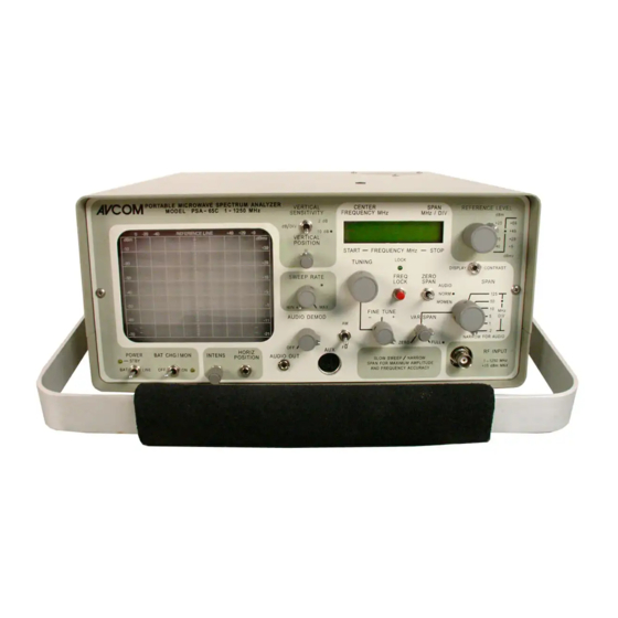
- Page 10 AVCOM's PSA-65C SWEEP VERTICAL VERT TUNING DIGITAL MULTI-FUNCTION ZERO REFERENCE RATE POSITION SENS FREQUENCY LIQUID CRYSTAL SPAN LEVEL LOCK DISPLAY POWER BAT CHG INTENS HORIZ AUDIO AUDIO AM-FM FINE RF INPUT SPAN DEMOD SELECTOR TUNE SPAN .1-1250MHz...
- Page 11 NOTE: An INTERNAL / EXTERNAL battery switch and EXTERNAL POWER jack are located on rear panel of the PSA-65C. When placed to "EXTERNAL" position, an external 11.5 - 15 VDC power source can provide power to the PSA-65C. This also charges internal batteries.
- Page 12 FREQUENCY is displayed by either 4 or 5 digits that permits frequency measurements accurate to 100 KHz. NOTE: For accurate frequency measurements, the PSA-65C must be in ZERO SPAN. The start and stop frequencies of the sweep are displayed when the on-screen...
- Page 13 15. VERTICAL POSITION Controls the position of the sweep. TO SET: With no signal present, the "REFERENCE LEVEL" switch set to 0 dBm, the SPAN control set to 1MHz/div, and the VARSPAN control tuned to the FULL position, adjust the sweep to be centered between the two small "tic"...
- Page 14 Place POWER switch into STBY position. Plug PSA-65C into a grounded outlet of correct voltage. NOTE: Amber STBY LED is illuminated. Set INT/EXT switch on rear panel to "INT", for INTernal.
- Page 15 INITIAL TURN-ON & SETUP Turn POWER switch to "LINE" and set the INTENSity control to approx. 80% of fully clockwise position. Center the VERTICAL POSITION control. After 30 seconds, a trace should appear on the screen. Set up the analyzer controls as follows: REFERENCE LEVEL to 0 dBm SPAN control to 125 MHz/div.
- Page 16 CONCLUSION Note the position of the VERTICAL, HORIZontal, and INTENSity controls so the PSA-65C can be put into service rapidly the next time it is used. This completes the User Familiarization and Preliminary Checkout of the PSA-65C.
-
Page 17: Psa-65C Specifications
PSA-65C SPECIFICATIONS FREQUENCY COVERAGE SENSITIVITY 1 MHz to 1250 MHz in one sweep. -95 dBm 200 KHz to 1000 MHz when optional 10 KHz Res B.W. installed. AMPLITUDE ACCURACY RESOLUTION BANDWIDTH + 2 dB typical Automatically selectable by Span Control FREQUENCY DISPLAY a) 3 MHz Res B.W. -
Page 19: Bail Handle Assembly Sequence
CORD WRAP PROCEDURE 1. Wrap power cord in a counterclockwise direction around cord guides. Only top and bottom hooks of cord guides are to be used. 2. Tuck plug behind outermost strands of wrapped cord. WRAP COUNTERCLOCKWISE PSA-65C - REAR PANEL VIEW... -
Page 20: Battery Pack Replacement Procedure
PSA-65C BATTERY PACK REPLACEMENT PROCEDURE Read the following instructions in their entirety before attempting battery replacement. 1. Unplug AC cord from unit. 2. Remove battery fuse, set aside to avoid loss. 3. Remove the four screws from battery access cover found on the bottom of the unit. -
Page 21: Limited Warranty
AVCOM makes no warranty, representation or guarantee regarding the suitability and/or fitness of its products for any particular purpose, nor does AVCOM assume any liability arising out of the application or use of this product or circuit, and specifically disclaims any and all liability including, without limitation, consequential or incidental damages.
Need help?
Do you have a question about the PSA-65C and is the answer not in the manual?
Questions and answers