Table of Contents
Advertisement
Advertisement
Table of Contents

Related Manuals for Lawn Solutions TA3016KAF1

Summary of Contents for Lawn Solutions TA3016KAF1
- Page 1 Form No. 3373-757...
- Page 2 Replacements may be ordered through the engine manufacturer. Lawn Solutions reserves the right to make changes or add improvements to its products at any time without incurring any obligation to make such changes to products manufactured previously.
-
Page 3: Introduction
Introduction CONGRATULATIONS on the purchase of your Lawn Solutions aerator. This product has been carefully designed and manufactured to give you a maximum amount of dependability and years of trouble-free operation. This manual contains operating, maintenance, adjustment, and safety instructions for your Lawn Solutions aerator. -
Page 4: Table Of Contents
Contents Introduction ............3 Adjustments ..........28 Safety ..............5 Auxiliary Pump Drive Belt Safety Alert Symbol ........5 Adjustment ........... 28 Safe Operating Practices ......5 Drive Belt Tension Adjustment ... 28 Safety and Instructional Decals ....10 Jackshaft Drive Chain Tension Specifications ............ -
Page 5: Safety
All operators and mechanics should be trained. Safety The owner is responsible for training the users. Safety Alert Symbol Never let children or untrained people operate or service the equipment. Local regulations This Safety Alert Symbol is used in this manual may restrict the age of the operator. - Page 6 DANGER DANGER In certain conditions gasoline is extremely In certain conditions during fueling, static flammable and vapors are explosive. electricity can be released causing a spark which can ignite gasoline vapors. A fire or A fire or explosion from gasoline can burn explosion from gasoline can burn you and you, others, and cause property damage.
- Page 7 Operation Stop engine, wait for all moving parts to stop, WARNING and engage parking brake: - Before refueling. Operating engine parts, especially the muffler, become extremely hot. Severe burns can occur on contact and debris, such as leaves, grass, WARNING brush, etc.
- Page 8 Use extreme care with attachments. These can DANGER change the stability of the machine and cause loss of control. Operating on wet grass or steep slopes can cause sliding and loss of control. Wheels Maintenance and Storage dropping over edges, ditches, steep banks, or ...
- Page 9 Battery gases can and accessories may alter the warranty, explode causing serious injury. traction, and safety of the machine. Failure to use original Lawn Solutions parts could cause Keep sparks, flames, or cigarettes away serious injury or death. Making unauthorized from battery.
-
Page 10: Safety And Instructional Decals
Familiarize yourself with the following safety If an attachment or accessory has been signs and instruction labels. They are critical to installed, make sure current safety signs are the safe operation of your Lawn Solutions visible. commercial aerator. 98-5954... - Page 11 116-6455 116-6459 116-6460 116-6456 116-6461 116-6457 116-6462...
- Page 12 116-6362 1. Fast 5. Wheels and tines rotate when moving forward 2. Slow 6. Wheels and tines rotate when moving rearward 3. Neutral 7. Rotate counterclockwise to decrease pressure 4. Reverse 8. Rotate clockwise to increase pressure...
- Page 13 116-6452 7. Engine – stop 1. Fast 8. Engine – run 2. Slow 9. Engine – start 3. Wheels and tines rotate when moving forward 10. Park brake – release 4. Wheels and tines rotate when moving rearward 11. Park brake – engage 5.
-
Page 14: Specifications
Specifications Model Number Serial Nos: LS02001 and Higher TA3016KAF1 Systems Tine Ground Engagement: Engages the tines with the ground. Engine Parking Brake Lever: Engages the parking Engine Specifications: See your Engine brake. Owner’s Manual Tine Down Pressure Control: Adjusts tine ... -
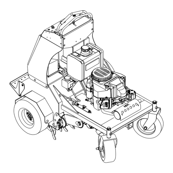
Page 15: Dimensions
Aeration Product Overview Aeration Width: 30 inches (76.2 cm) Tines: Qty: 48 Tine Down Pressure: 0-1200 lbs Core Depth: 2-5 inches (5.1-12.7 cm) Holes per square foot: 4.6 Dimensions Overall Width: 47.75 inches (121.3 cm) Overall Length: 64 inches (162.6 cm) Overall Height: 52 inches (132.1 cm) Figure 3... -
Page 16: Operation
Choke Control Operation Located on the control console (see Figure 4). Note: Determine the left and right sides of the Choke is used to aid in starting a cold engine. The machine from the normal operating position. choke control is pulled out to be in the “ON” position and pushed in to be in the “OFF”... -
Page 17: Pre-Start
result in fuel leakage or damage to the engine or Fuel Shut-Off Valve emission system. Located under the fuel tank. Make sure you understand the controls, their The fuel shut-off valve is used to shut off the fuel locations, their functions, and their safety when the machine will not be used for a few days, requirements. - Page 18 Adjusting the Tine Down Pressure Driving the Machine Adjust the plug depth by rotating the tine down CAUTION pressure control. Rotate the control counterclockwise to decrease the hydraulic down Machine can spin very rapidly by positioning pressure to remove a shorter plug. Rotate one lever too much ahead of the other.
-
Page 19: Transporting
The machine will move faster the farther the To turn left or right, release pressure on the motion control levers are moved from the motion control lever toward the desired turn neutral position. direction. 4. To stop, position both motion control levers To make zero turns, lift your foot off of the in the neutral position. - Page 20 WARNING Loading a unit on a trailer or truck increases the possibility of backward tip-over. Backward tip-over could cause serious injury or death. Use extreme caution when operating a unit on a ramp. Use only a single, full width ramp; Do Not use individual ramps for each side of the unit.
-
Page 21: Maintenance
Maintenance Note: Determine the left and right sides of the machine from the normal operating position. WARNING WARNING While maintenance or adjustments are being The engine can become very hot. Touching a made, someone could start the engine. hot engine can cause severe burns. Accidental starting of the engine could Allow the engine to cool completely before seriously injure you or other bystanders. -
Page 22: Periodic Maintenance
Change the engine oil. Remove the engine shrouds and clean cooling fins. Grease the front caster pivots. Grease the jackshaft bearings. Every 100 hours Grease the tine shaft bearings. Grease the wheel bearings Grease the control pivots. - Page 23 recommended time interval to bring the charge up 2. Make sure the booster is a good and fully to a full charge of 12.6 volts or greater. charged lead acid battery at 12.6 volts or greater. Use properly sized jumper cables (4 to Important: Make sure the negative battery 6 AWG) with short lengths to reduce voltage cable is disconnected and the battery charger...
-
Page 24: Check Tines
Do Not rely solely on mechanical or hydraulic jacks for support. Use adequate jack stands or equivalent support. 3. Clean off any oil, debris, or dirt build-up on the machine, especially under the chain guards, around the fuel tank, around engine and exhaust area. -
Page 25: Check For Loose Hardware
Before the new filter is installed, apply a thin Check for Loose Hardware coating of oil on the surface of the rubber seal. Service Interval: Before each use or daily Turn filter clockwise until rubber seal contacts 1. Stop engine, wait for all moving parts to stop, the filter adapter, then tighten filter an and remove key. -
Page 26: Check Condition Of Chains
3. Check the auxiliary pump drive belt condition; Lubricate Grease Fittings belt should be snug. Note: See Chart for service intervals. 4. Check the condition of the transmission drive 1. Stop engine, wait for all moving parts to stop, belt. and remove key. -
Page 27: Change Auxiliary Hydraulic Reservoir Fluid
were originally installed at the factory to keep the Torque plugs to 180 in-lb (244 N-m). Continue fuel line away from components. to add Mobil 1 15W-50 synthetic motor oil until it reaches the FULL COLD line on the Change Auxiliary Hydraulic expansion reservoir. -
Page 28: Check Spark Arrester (If Equipped)
system. When the transaxle operates at Adjustments normal noise levels and moves smoothly forward and reverse at normal speeds, then Note: Shut off engine, wait for all moving parts the transaxle is considered purged. to stop, engage parking brake, and remove key before servicing, cleaning, or making any Note: Do Not change the hydraulic system oil adjustments to the unit. -
Page 29: Drive Wheel Chain Tension Adjustment
6. Adjust motion controls as stated in the 8. Check the park brake; repeat steps 5 through 7 Motion Control Linkage Adjustment if necessary. section. Motion Control Linkage Drive Wheel Chain Tension Adjustment Adjustment 1. Park the machine on level ground. 1. -
Page 30: Cleaning
Waste Disposal Cleaning Motor Oil Disposal Clean Engine and Exhaust Engine oil and hydraulic oil are both pollutants to System Area the environment. Dispose of used oil at a certified recycling center or according to your state and Service Interval: Before each use or daily local regulations. -
Page 31: Troubleshooting
Troubleshooting Important: It is essential that all operator safety mechanisms be connected and in proper operating condition prior to use. When a problem occurs, do not overlook the simple causes. For example: starting problems could be caused by an empty fuel tank. The following table lists some of the common causes of trouble. - Page 32 Engine loses power. 1. Engine load is excessive 1. Reduce the ground speed or aeration depth. 2. Clean or replace the air cleaner 2. Air cleaner is dirty. element. 3. Oil level in the crankcase is low. 3. Add oil to the crankcase. 4.
- Page 33 NOTES...
- Page 35 Figure 11 This page may be copied for personal use. 1. The maxium slope you can safely operate the machine on is 15 degrees. Use the slope indicator to determine the degree of slope of hills before operating. Do Not operate this machine on a slope greater than 15 degrees. Fold along the appropriate line to match the recommended slope.
Need help?
Do you have a question about the TA3016KAF1 and is the answer not in the manual?
Questions and answers