Table of Contents
Advertisement
Advertisement
Table of Contents

Subscribe to Our Youtube Channel
Related Manuals for ASTEC RT160

Summary of Contents for ASTEC RT160
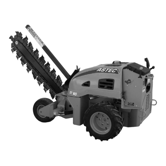
- Page 1 RT160 Trencher Operator’s Manual AU104488...
- Page 2 • Learns and practices safe use of machine controls in a safe, clear area before operating this machine on a job site. It is your responsibility to observe pertinent laws and regulations and follow Astec instructions on machine operation and maintenance. © 2005 Astec Underground...
-
Page 3: Table Of Contents
WHEELS AND TIRES ....31 RT160 TRENCHER ......1 INSTALLING DUAL WHEELS . - Page 4 TABLE OF CONTENTS AU104488 C6B...
-
Page 5: To The Owner
Make sure this Astec Trencher. Refer to the Index at the end of this manual is complete and in good condition. Contact your manual for locating specific items about your machine. -
Page 6: Right, Left, Front And Rear Of Machine
TO THE OWNER RIGHT, LEFT, FRONT AND REAR OF MACHINE Right-hand and left-hand, when used in this manual, indicate the right and left sides of the machine as seen from the operators position facing the machine engine and operating the controls. VIEWED FROM RIGHT SIDE FORWARD DIRECTION OF TRAVEL... -
Page 7: Identification Numbers
Make a record of the numbers. Keep the record and your Manufacturer’s Statement of Origin in a safe place. If the machine is stolen, report the numbers to your local law enforcement agency. RT160 Trencher MACHINE MODEL NUMBER: 1. PRODUCT IDENTIFICATION NUMBER (P.I.N.) ________________________________________________________ 2. -
Page 8: Machine Components - Left Side
IDENTIFICATION NUMBER MACHINE COMPONENTS - LEFT SIDE RT160091 1. RESTRAINT BAR 4. DIGGING CHAIN CONTROL 7. TRENCHER BOOM 2. ENGINE HOOD 5. DIGGING CHAIN 8. REAR TIE DOWNS 3. GUIDE WHEEL 6. OPERATORS MANUAL STORAGE 9. HYDRAULICS ACCESS COVER MACHINE COMPONENTS - RIGHT SIDE RT160085 1. -
Page 9: Safety/Decals/Hand Signals
Caution is YELLOW. machine before you operate or service the machine. See your Astec dealer if you have any questions. ISO two panel pictorial symbol decals are shown in both READ THIS MANUAL COMPLETELY and make sure you... -
Page 10: Before Operations
SAFETY BEFORE OPERATIONS Before beginning any trenching, drilling or other construction work it is your responsibility to be aware of all such utility lines buried in the area of • Avoid loose fitting clothing, loose or uncovered long your project and to avoid them. hair, jewelry and loose personal articles. -
Page 11: Failure In Operation
SAFETY FAILURE IN OPERATION • Stay away from hazardous areas such as ditches, overhangs, etc. Walk around the work area before you start and look for hazards. • In the event of poor performance or machine failure, stop the machine immediately and report the matter. •... -
Page 12: Maintenance
• When you replace parts on your machine, always use • If you are exposed to or come in contact with Astec parts. See your dealer. hazardous chemicals you can be seriously injured. The fluids, lubricants, paints, adhesives, coolants, etc., •... -
Page 13: Fire Or Explosion Prevention
SAFETY FIRE EXTINGUISHER • Before you service your machine, check the MSDS for each fluid, lubricant, etc., used in this machine. This information indicates what the risks are and how to Type of Fire Extinguisher service the machine safely. Follow this information It is recommended that you have a fire extinguisher close when servicing the machine. -
Page 14: Safety Decals
Replace any missing or damaged safety decal and keep all safety decals clean. See your Astec dealer for new safety decals. • Make sure that you read all safety and instruction decals. Check these decals every day before you start. - Page 15 SAFETY RT160081 283607A1, RT160145 AND RT160019 6. This decal is located near the front tire. If equipped with Hydra-borer, this decal is also located on the hydra-borer shield. AU103971 4. This decal is located in the engine compartment by the hydraulic reservoir. RT160016 RT160001, H438909, AND H438910 7.
- Page 16 SAFETY RT160074 RT160092 384267A1 9. This decal is located by the control panel. AU103976 11. The Hot Surfaces decal is found on the engine access covers. RT160073 RT160077 12. Tie Downs 321-3214 10. This decal is located near the control panel. TIE DOWN 94F25 Tie downs are not to be used for towing.
-
Page 17: Hand Signals
SAFETY HAND SIGNALS It is recommended that you and the flagman on the job use hand signals for communications. Before you start, make sure that you both understand the signals that will be used. PDE0003A PDE0004A PDE0003 COME TO ME GO THIS FAR MOVE AWAY FROM ME PDE0005A... - Page 18 SAFETY NOTES AU104488 C6B...
-
Page 19: Instruments And Controls
INSTRUMENTS AND CONTROLS CONTROL PANEL RT160073 FUEL GAUGE 1. IGNITION SWITCH 2. FUEL GAUGE The fuel gauge (2) indicates the amount of fuel in the fuel 3. HOURMETER tank. 4. AMMETER HOURMETER 5. OPERATOR PRESENCE TRIGGER 6. GROUND DRIVE CONTROL The hourmeter (3) indicates the total hours of operation 7. -
Page 20: Creep Control
INSTRUMENTS/CONTROLS From the NEUTRAL position, push the joystick slightly REARWARD (away from you) for reverse ground travel. Push the joystick further to increase the reverse ground speed. Pull the joystick slightly forward to decrease the reverse ground speed. While moving push the joystick slightly LEFT or RIGHT to turn. -
Page 21: Throttle Control
INSTRUMENTS/CONTROLS ENGINE CHOKE CONTROL Before you start an engine that is cold, pull the choke control (11) out. Then, after the engine is started and the engine temperature increases, push the choke control in. RT160012 The engine controls are accessible through an opening below the control panel. - Page 22 INSTRUMENTS/CONTROLS NOTES AU104488 C6B...
-
Page 23: Operating Instructions
OPERATING INSTRUCTIONS ENGINE OPERATION RUN-IN MAINTENANCE SCHEDULE The following items are to be done during the Run-In Before Starting The Engine Period and are in addition to the items listed above as well as those listed in the Lubrication/Maintenance Chart. : Before starting engine, study WARNING After Delivery Check... -
Page 24: Starting The Engine
OPERATING INSTRUCTIONS 1. If you add water to the battery and the temperature 5. Release the key as soon as the engine starts to run. If is below 0°C (32°F), make sure you charge the the engine starts and stops, DO NOT actuate the battery or run the engine for approximately 2 hours. -
Page 25: Booster Battery Connections
OPERATING INSTRUCTIONS BOOSTER BATTERY CONNECTIONS PARKING AND STOPPING THE ENGINE WARNING: Batteries contain acid 1. When the work day is finished, make sure the explosive gas. Explosion can result from sparks, machine is parked on level ground. The machine must flames or wrong cable connections. -
Page 26: Trencher Operation
Install a crumber wear blade (shoe) (2) which is 25.4 mm Then, see your Astec dealer and ask for complete (1 in) less width than the trench width. information on trencher parts. -
Page 27: Trencher Chain And Teeth
OPERATING INSTRUCTIONS Boom Position When Digging Chain Tension If you adjust the digging chain too tight or too loose, the For the best digging performance and smoothest machine digging efficiency of the trencher is decreased and the operation, the boom must be in the full down digging wear of the parts is increased. -
Page 28: Before You Operate
Additional digging teeth combinations may be NOTE: 6. Move the throttle to FAST. available to meet particular soil conditions. See your Astec dealer for additional information. 7. Press the trigger on the ground drive control joystick. 8. Engage the digging chain. Slowly lower the trencher BEFORE YOU OPERATE boom into the ground to the necessary depth. -
Page 29: Transporting The Machine Ona Trailer
OPERATING INSTRUCTIONS TRANSPORTING THE MACHINE ON MOVING A DISABLED MACHINE A TRAILER Know the rules, regulations, laws WARNING: Personal injury or death can result WARNING: and safety equipment necessary for transporting when you tow a disabled machine incorrectly. or operating this machine on a road or highway. Read the following recommendations. -
Page 30: Hydra-Borer Operation
OPERATING INSTRUCTIONS HYDRA-BORER OPERATION Before beginning underground IMPORTANT: operations, always check with appropriate local utility companies to determine if any underground cables, wires, CLEAR THE WORK AREA OF ALL WARNING: pipes, etc. may be encountered during operations. BY-STANDERS. DURING HYDRA-BORER OPERATIIONS KEEP SPECTATORS AWAY. - Page 31 OPERATING INSTRUCTIONS STARTING HOLE GUIDE ANCHORS TARGET HOLE 235L93 5. Attach the required quantity of drill stem segments to the Hydra-Borer and lower drill stem into starting trench so that the drill stem passes through the guide rings on the guide anchor assemblies. 6.
- Page 32 OPERATING INSTRUCTIONS Dry Boring 3. Begin operations by boring a pilot hole. Use a fishtail bit (9) for tightly compacted soil or a compaction bit (10) for soils which are loose or granular. Attach the 2. MALE 1. UNIVERSAL JOINT drill bit to the drill stem using a female quick lock ADAPTER adapter (8).
- Page 33 OPERATING INSTRUCTIONS Wet Boring 3. Supply a water pump and connect a hose from the water pump to the water coupler (2) and from the fluid source (tank, pond) to water pump inlet. 1. UNIVERSAL JOINT 4. Begin boring operations with a fishtail bit (7) to bore 2.
- Page 34 OPERATING INSTRUCTIONS NOTES AU104488 C6B...
-
Page 35: Wheels And Tires
WHEELS AND TIRES Correct Methods for Adding Air or Servicing Tires : DO NOT weld to wheel or rim when WARNING Check the air pressure and the condition of the tires every a tire is installed. Welding will cause an explosive 50 hours of operation. - Page 36 WHEELS/TIRES Tire or Rim Service Tire Air Pressures Always have a qualified tire technician service the tires Check the pressure and the condition of the tires every 50 and rims for this machine. It is recommended that you hours of operation. have this technician inflate the tires.
-
Page 37: Installing Dual Wheels
WHEELS/TIRES INSTALLING DUAL WHEELS 1. Dual Wheel Bracket 3. Dual Wheel 2. Wheel Nut 4. Dual Wheel Bolt RT160041 1. Loosen and remove all wheel nuts from the wheel on the machine. 2. Install a dual wheel bracket on the machine wheel. 3. - Page 38 WHEELS/TIRES NOTES AU104488 C6B...
-
Page 39: Lubrication
B801147T PIC00056 Before you service the machine, put a Do Not Operate tag on the control panel. This tag, Astec part number RT160075 AU103157 is available from your dealer. The Do Not Operate tag is included with your machine. -
Page 40: Capacities And Lubricant Specifications
Type of Fuel ........LEAD FREE Gasoline (with minimum average octane rating of 86 or higher) HYDRAULIC SYSTEM Reservoir Capacity .........................18.9 L (5 U.S. Gal) Total System Capacity....................... 25.6 L (6.75 U.S. Gal) Specifications ......................Astec AW46 Hydraulic Fluid GREASE FITTINGS Type of Lubricant ....................251H EP Multi-Purpose Grease FILTERS Air Filter ............................ -
Page 41: Lubrication/Maintenance Chart
LUBRICATION LUBRICATION/MAINTENANCE CHART SCHEDULE FREQUENCY IN HOURS FREQUENCY SERVICE POINTS As Required 44 Hydraulic Return Filter 42 Air Filter (See Note 2) 41 Engine Oil Level (See Note 2) 44 Hydraulic Reservoir Oil Level (See Note 2) Every Day 49 Trencher Chain Wear Pad (See Note 2) 39 Trencher Boom Pivot (See Note 2) 48 Trencher Chain Tension (See Note 2) 42 Air Filter (See Note 3) -
Page 42: Access Doors And Covers
LUBRICATION ACCESS DOORS AND COVERS RT160005 RT160021 ENGINE ACCESS COVER SHOWN CLOSED ENGINE ACCESS COVER SHOWN OPEN RT160068 RT160006 HYDRAULIC SYSTEM ACCESS COVER REMOVED RIGHT SIDE ACCESS COVER REMOVED RT160010 RT160014 AIR CLEANER AND ENGINE CONTROLS ACCESS OPENINGS LEFT SIDE ACCESS COVER REMOVED AU104488 C6B... -
Page 43: Grease Fittings Locations
LUBRICATION GREASE FITTINGS LOCATIONS Service grease fittings every 10 hours of operation or Service the front axle grease fitting every 10 hours of once each day. operation or once each day. Front Tire Axle Trencher Boom Pivot RT160072 RT160086 Trencher Boom Pivot Bearing ......1 Fitting Front Tire Axle ..........1 Fitting The trencher boom pivot grease fitting is accessible from above by opening the engine access hood, and through... -
Page 44: Engine Lubrication
LUBRICATION ENGINE LUBRICATION Engine Oil Selection Astec Engine Oil is recommended for use in your engine. Astec Engine Oil will lubricate your engine correctly under all operating conditions If Astec Multi-Viscosity is not available, use only oil meeting API engine oil service category CF-4 OR CG-4. - Page 45 LUBRICATION Engine Oil Level 2. Place a suitable container below the engine to catch the used oil, then remove the filler cap and the drain bolt. Full RT160044 3. Allow the used oil to drain completely, then reinstall the drain bolt, and tighten it securely. RT160043 Make sure the engine is not running and the machine is 4.
-
Page 46: Air Filtering System
LUBRICATION 11. Install the filler cap and the dipstick. 12. Start the engine. Run the engine at idle for approximately 2 minutes. Check for oil leaks. 13. Stop the engine. 14. Wait approximately 5 minutes and check the oil level. If the oil level is below the UPPER mark, add oil to raise the oil to the UPPER mark. -
Page 47: Fuel System
If you keep fuel in storage for a period of time, you can accumulation or sediment, take the machine to get foreign material or water in the fuel storage tank. your authorized Astec servicing dealer. Many engine problems are caused by water in the fuel. Draining the Carburetor For Storage Fuel Tank Filler Cap Gasoline will oxidize and deteriorate in storage. -
Page 48: Hydraulic Oil System
LUBRICATION You can avoid fuel deterioration problems by draining the fuel tank and carburetor. The fuel tank flow/drain plug is located near the bottom of the fuel tank, accessible from beneath the machine. 1. Disconnect the fuel line to the engine, and drain the fuel tank into an approved gasoline container. - Page 49 LUBRICATION DO NOT use a filter strap wrench to IMPORTANT: 4. See Hydraulic Return Line Filter in this manual and tighten the filter. A strap wrench can cause a leak if the replace the return filter. filter is dented. 5. Reinstall the drain plug. 4.
- Page 50 LUBRICATION NOTES AU104488 C6B...
-
Page 51: Adjustment/Maintenance
Frequent fuse failure usually indicates a short circuit or an overload in the electrical system. If a fuse burns out 7. Attach the spark plug caps. frequently, take the machine to an authorized Astec A loose spark plug can overheat and damage the NOTE: service dealer for repair. -
Page 52: Digging Chain Tension
ADJUSTMENT/MAINTENANCE DECREASING CHAIN TENSION 2. Use a brush to remove carbon deposits from the spark arrester screen. Be careful to avoid damaging the screen. The spark arrester must be free of breaks and holes. Replace the spark arrester if it is damaged. RT160050 RT160059 CHAIN ADJUSTMENT LOCATION... -
Page 53: Increasing Chain Tension
Class A, B and C type fires. The operating temperature is from -54 to 49°C (-65 to 120°F). DIGGING CHAIN WEAR PADS See your Astec dealer for the proper type of fire NOTE: extinguisher. Inspection and Care... - Page 54 ADJUSTMENT/MAINTENANCE NOTES AU104488 C6B...
-
Page 55: Electrical
ELECTRICAL BATTERY The engine is equipped with a fuel-cut solenoid that allows fuel to flow to the carburetor main jet when the ignition switch is in the ON or START position and stops Before you service a battery, WARNING: the flow to the main jet when the engine switch is in the always wear face protection, protective gloves OFF position. - Page 56 Follow the instructions on the container. This cleaner does not need water. 2. Use baking soda or ammonia and flush the outside of the battery with water. If you do not have Astec Battery Saver, use other special cleaners to prevent corrosion on the battery terminals.
-
Page 57: Machine Storage
3. Paint any areas where the paint has been damaged. 5. Lubricate the machine at all grease fittings. 4. Change the engine oil and oil filters. 6. Remove the Astec Rust and Corrosion Preventative from the hydraulic cylinder rods and control valve 5. Remove the spark plugs. - Page 58 MACHINE STORAGE NOTES AU104488 C6B...
-
Page 59: Boom Identification
SPECIFICATIONS BOOM IDENTIFICATION BOOM LENGTH RH97D036 TABLE 1: ROCK BOOM Boom Maximum Dig Maximum Dig Cutting Length in Depth in Width in Stations Inches Inches 74.0 108.5 143.0 AU104488 C6B... -
Page 60: Basic Machine Dimensions
SPECIFICATIONS BASIC MACHINE DIMENSIONS RT160042B A. Transport Height (4 Foot Boom Fully Raised) ................157.48 cm (62 in) B. Wheel Base......................... 92.71 cm (36.5 in) C. Overall Length with 4 ft. Boom & Crumber, Full Raised .............. 165.1 cm (65 in) D. -
Page 61: Hydraulic System
SPECIFICATIONS HYDRAULIC SYSTEM Ground Drive Pump Flow @ 2,320 psi......................43.15 l/min (11.4 gpm) Trencher Drive Pump Flow @ 3,000 psi......................49.21 l/min (13 gpm) Auxilliary Pump for Accessory Functions Flow @ 2,400 psi......................49.21 l/min (13 gpm) Hydraulic Reservoir Capacity .......................18.9 L (5 U.S. Gal) SPEED Maximum Speed Forward........................ - Page 62 SPECIFICATIONS TORQUE SPECIFICATIONS - DECIMAL HARDWARE Use the torques in this chart when special torques are not given. Grade 8 Bolts, Nuts, and Studs These torques apply to fasteners with both UNC and UNF threads as received from suppliers dry, or when lubricated with engine oil.
- Page 63 SPECIFICATIONS TORQUE SPECIFICATIONS - METRIC HARDWARE Use the following torques when specifications are not given. Grade 10.9 Bolts, Nuts, and Studs These values apply to fasteners with both coarse and fine threads as received from supplier, plated or unplated, or when 10.9 lubricated with engine oil.
- Page 64 SPECIFICATIONS TORQUE SPECIFICATIONS - STEEL HYDRAULIC FITTINGS 37 Degree Flare Fitting Nom. SAE Dash Size Tube OD/Hose ID Thread Size Newton metres Pound-Inches 5/16 - 24 8 to 9 72 to 84 3/8 - 24 11 to 12 96 to 108 6.4 mm (1/4 inch) 7/16 - 20 14 to 16...
- Page 65 SPECIFICATIONS Split Flange Mounting Bolts Size Newton metres Pound-Inches 5/16-18 20 to 27 180 to 240 3/8-16 27 to 34 240 to 300 7/16-14 47 to 61 420 to 540 Pound-Feet 1/2-13 74 to 88 55 to 65 5/8-11 190 to 203 140 to 150 O-Ring Boss End Fitting or Lock Nut...
- Page 66 SPECIFICATIONS Pipe fittings Nom. SAE Dash Size Thread Size TFFT (Turns For Finger Tight) 1/8 - 27 2.0 - 3.0 1/8 - 27 2.0 - 3.0 1/8 - 27 2.0 - 3.0 1/8 - 27 2.0 - 3.0 1/4 - 18 1.5 - 3.0 3/8 - 18 2.0 - 3.0...
- Page 67 SPECIFICATIONS NOTES AU104488 C6B...
- Page 68 SPECIFICATIONS AU104488 C6B...
-
Page 69: Index
INDEX Adding Air .............. 31 Hand Signals ............13 After Delivery Check ........1, 19, B1 Height Of Machine ..........56 Air Cleaner Element ..........42 Hood ..............38 Air Pressure ............31 Horsepower ............56 Ammeter ............... 15 Hot Weather Conditions .......... 19 Attachment Control .......... - Page 70 INDEX Safety Decals ............5 Safety Message ............5 Serial Number ............3 Servicing Tires ............31 Spark Arrester ............47 Spark Plug ............. 47 Starter Fuse ............47 Starting The Engine ..........20 Starting The Trench ..........24 Stopping The Engine ..........21 Stopping The Machine ..........
- Page 71 AFTER DELIVERY CHECK AFTER DELIVERY CHECK After First 50 Hours of Operation of New Machine Date of Check________________Hourmeter Reading__________________________________________ hours MACHINE: Product Identification Number ________________________________________________________ OWNER: Name ______________________________________________________________________________ Address ______________________________________________________________________________ DEALER:Name ______________________________________________________________________________ Address ______________________________________________________________________________ TRENCHER PLANETARY LUBRICATION Check trencher planetary oil level. Lubricate all pivot points.
- Page 72 AFTER DELIVERY CHECK NOTES AU104488 C6B...
- Page 73 AFTER DELIVERY CHECK AFTER DELIVERY CHECK After First 50 Hours of Operation of New Machine Date of Check________________Hourmeter Reading__________________________________________ hours MACHINE: Product Identification Number ________________________________________________________ OWNER: Name ______________________________________________________________________________ Address ______________________________________________________________________________ DEALER:Name ______________________________________________________________________________ Address ______________________________________________________________________________ TRENCHER PLANETARY LUBRICATION Check trencher planetary oil level. Lubricate all pivot points.
- Page 74 AFTER DELIVERY CHECK NOTES AU104488 C6B...
- Page 75 State of California to cause cancer, birth defects, and other reproductive harm. Astec reserves the right to make improvements in design or changes in specifications at any time without incurring any obligation to install them on units previously sold. AU104488 C6B...
- Page 76 AFTER DELIVERY CHECK NOTES AU104488 C6B...
Need help?
Do you have a question about the RT160 and is the answer not in the manual?
Questions and answers