Table of Contents
Advertisement
Advertisement
Table of Contents

Related Manuals for Blackboard MF4100


Summary of Contents for Blackboard MF4100
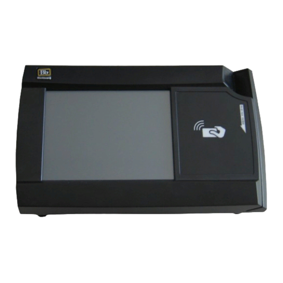
- Page 1 MF4100 Installation Guide...
- Page 2 This Class B digital apparatus complies with Canadian ICES-003 Cet appareill numérique de la classes B est conform à la norme NMB-003 du Canada This device complies with Part 15 of the FCC Rules. Operation is subject to the following two conditions: (1) This device may not cause harmful interference, and (2) this device must accept any interference received, including interference that may cause undesired operation.
-
Page 3: Table Of Contents
Attended Wall Mount Installation Unattended Wall Mount Installation 10 Table Top Mount Installation 10 Table Top Mount With The VESA Mounting Bracket 12 Table Top Mount Without The VESA Mounting Bracket 13 MF4100 Features and Specifications 3, 2009 RINTED OVEMBER... - Page 4 I G U R E S Figure 1-1 Multi-Function Reader MF4100..............1 Figure 1-2 Cat-5 Cable and Power Supply ..............2 Figure 1-3 MF4100 Hardware Kit ................2 Figure 1-4 VESA Bracket.....................2 Figure 1-5 VESA Bracket Screw Position - Attended ..........3 Figure 1-6 VESA Bracket Screw Position - Unattended ..........4...
-
Page 5: Mf4100 Installation Uide
• Copy Reader • Laundry Reader • POS Terminal The MF4100 supports full video and audio playback allowing for a rich video experience for: • Advertising • Alerts and notifications • Other special messages via a full color touch screen... -
Page 6: Figure 1-2 Cat-5 Cable And Power Supply
A hardware kit is provided with a security plate, rubber feet, and screws to aid in mounting the unit. Cat-5 Cable Wall Mount Power Supply Figure 1-2 Cat-5 Cable and Power Supply Security Plate Screw kit Rubber Feet Figure 1-3 MF4100 Hardware Kit Figure 1-4 VESA Bracket 3, 2009 RINTED OVEMBER... -
Page 7: Vesa Mounting Bracket Overview
RACKET VERVIEW The MF4100 Multi-Function Reader ships with a VESA style mounting bracket. The mounting bracket is optional, but simplifies installation on vertical and horizontal surfaces. The VESA mounting bracket is adjustable to allow the MF4100 to be positioned at different angles. -
Page 8: Assembly Details
V E S A M O U N T I N G R A C K E T V E R V I E W For Unattended use, the mounting position can be fixed by placing the lock screws in the position shown below. -
Page 9: Mount The Mf4100
E A D E R N S T A L L A T I O N U I D E 1 2 9 5 O C U M E N T MF4100 OUNT THE MF4100 MOUNTING OPTIONS Wall Mount Installation •... -
Page 10: Wall Mount Installation
(Page: 8) Attended Wall Mount Installation Find a location on a single gang box to mount the MF4100. Ensure there is enough clearance for the operator to access the touchscreen and swipe cards. Remove the two base extensions by removing the 4 screws (1/8” Pin hex driver). -
Page 11: Figure 1-11 Mf4100 Cable Ports
Note the orientation of the VESA bracket to the security plate. Security plate Figure 1-12 Attended Wall Mount VESA Bracket Orientation Place the MF4100 assembly on the pivot plate, and then secure using four M4 x 6mm machine screws provided in the hardware kit. 3, 2009... -
Page 12: Figure 1-13 Reader Secured To Pivot Plate - Attended Wall Mount
Position the pivot plate to the desired angle, and then tighten the 2 locking screws (1/8” pin hex driver). Unattended Wall Mount Installation Find a location on a single gang box to mount the MF4100. Ensure there is enough clearance for the operator to access the touchscreen and swipe cards. -
Page 13: Figure 1-15 Unattended Wall Mount Vesa Bracket Orientation
Security plate Figure 1-15 Unattended Wall Mount VESA Bracket Orientation Place the MF4100 assembly on the pivot plate, and then secure using four M4 x 6mm machine screws provided in the hardware kit. Position the pivot plate to the desired angle, and then tighten the 2 locking screws (1/8” pin hex driver). -
Page 14: Figure 1-16 Vesa Bracket Rubber Feet
Route the required cables through the VESA bracket cable hole, and then the pivot bracket hole. Install cables to the connectors of the MF4100. See: MF4100 Cable Ports (Page: 7). Place the security plate onto the MF4100, and then route the cables through the plate opening. 3, 2009 1-10 RINTED OVEMBER... -
Page 15: Figure 1-17 Table Top Mount - With Vesa Bracket Cable Route
1 2 9 5 O C U M E N T For a fixed 15 degree angle, install the MF4100 so the security plate is located near the hinge of the VESA mounting bracket. Place the locking screws in the unattended position. -
Page 16: Figure 1-18 Reader Rubber Feet Installation Locations
Ensure there is enough clearance for the operator to access the touchscreen and swipe cards. Install the rubber feet provided in the hardware kit to each corner of the MF4100 plastic bottom cover. The rubber feet are self-adhesive. The bottom cover has round depressions in the plastic to locate the rubber feet. -
Page 17: Mf4100 Features And Specifications
E A D E R N S T A L L A T I O N U I D E 1 2 9 5 O C U M E N T MF4100 F EATURES AND PECIFICATIONS EATURES • Host communications via 10/100 Base-T ethernet (IP) or 802.11 b/g wireless •...
Need help?
Do you have a question about the MF4100 and is the answer not in the manual?
Questions and answers