
Related Manuals for Sartorius PR 5610


Summary of Contents for Sartorius PR 5610
- Page 1 This document courtesy of: Data Weighing Systems, Inc. Contact Us For immediate assistance call 1-800-750-6842...
- Page 2 System Weighing Controller PR 5610 Installation Manual Installation manual 9499 050 60004 Edition 4 27.07.2004 A4 FZ for PR 5610 Release: 3.12 Sartorius Hamburg GmbH, Meiendorfer Str. 205, 22145 Hamburg, Germany Tel:+49.40.67960.303 Fax:+49.40.67960.383...
- Page 3 This product is partly copyrighted. It may not be modified or copied and may not be used without purchasing or written authority from the copyright owner (SARTORIUS). By using this product, you agree to be bound by the terms stated herein.
-
Page 4: Table Of Contents
PR 5610 Installation Manual List of Contents Contents SAFETY HINTS, ELECTRICAL PROTECTION CLASS ................5 ......................... 5 PPLICATION OF THE INSTRUMENT ..............................5 NITIAL INSPECTION ............................5 EFORE COMMISSIONING 1.3.1 Installation..............................5 1.3.2 Electrostatically sensitive components ......................6 1.3.3 Protective earth ............................6 1.3.4... - Page 5 List of Contents PR 5610 Installation Manual 4.1.4 Cold / Warm start ............................58 ........................59 ISPLAY ELEMENTS AND CONTROLS 4.2.1 Control signals............................59 4.2.2 Language ..............................59 4.2.3 Operating concept ‘Commissioning’ ......................60 ................................61 AIN MENU 4.3.1 Function setup ............................61 4.3.2...
- Page 6 Customer-specific weighing point (user) ....................136 5.6.11 GWT Scale ..............................138 5.6.12 Sartorius scale (xBPI)..........................139 ............................140 MENU ERVICE 5.7.1 Available memory in PR 5610 ........................140 5.7.2 Show hardware configuration ........................141 5.7.3 Testing the input and output modules ....................... 141 Sartorius...
- Page 7 Safe condition ............................147 6.1.5 EC-Declaration of Conformity ......................... 148 6.1.6 Certificate of type approval PR 1713, PR 5610 (X5), PR 5710 (X6) ............149 6.1.7 Location of seals PR 1713, PR 5610 (X5) ....................150 6.1.8 Location of seals PR 5710 (X6), foil PR 5610 (X5).................. 151 ..............................
-
Page 8: Safety Hints, Electrical Protection Class
Check the contents of the consignment for completeness and note whether any damage has occurred during transport. If the content is incomplete or damaged, a claim must be filed with the carrier immediately and the Sartorius sales or service organization must be informed to permit repair or replacement of the unit. 1.3 Before commissioning... -
Page 9: Electrostatically Sensitive Components
Power connection PR 5610/X0 The PR 5610/X0 is designed for 230 V AC / 115 V AC with 50 to 60 Hz supply The adjusted operating voltage must correspond to the nominal power voltage. Changing over from 230 V (... -
Page 10: Failure And Excessive Stress
Power supply PR 5610/X1 The PR 5610/X1 is designed for operation with 24 V AC with 50 to 60 Hz or 24 V DC supply, use mains screw L and N of terminal block to connect 24 V AC or 24V DC supply. For earth connection, refer to chapter 1.3.3. -
Page 11: Repair And Maintenance
PR 5610 Installation Manual 1.4 Repair and maintenance Repairs are subject to checking and can be carried out only at Sartorius Hamburg GmbH. In case of defect or functional trouble, please, contact your local SARTORIUS organization for repair. When returning the instrument for repair, an exact and complete fault description must be supplied. -
Page 12: Disposal
PR 5610 Installation Manual Safety Hints 1.5 Disposal Electronics scrap is special waste. Please, follow your local disposal regulations. 1.6 Cleaning If necessary, the front panel can be cleaned using a damp, soft cloth. Use only little water or isopropyl alcohol for moisturizing. -
Page 13: System Weighing Controller
• Extensible by means of options (4 slots), RAM-extension (2 sockets). • Interfaces (except the RS 232, analog input, BCD output) are galvanically isolated. • Power connection for 230 V/ 115 V AC (PR 5610/X0) or 24 V AC / DC (PR 5610/X1), protection class I (protective earth). -
Page 14: Options
PR 5610 Installation Manual Function Description 2.2 Options PR 5610 Periphery PR 1713/05 PR1713/05 Fieldbus master 1 MByte Extension static RAM Slot 4 RAM sockets PR1721/01 PR1721/02 PR1721/04 PR1721/01 PR1721/02 PR1721/04 Fieldbus Profibus- Interbus-S DeviceNet Profibus- Interbus-S DeviceNet Slave Weight... -
Page 15: Program Extensions (Optional)
Function Description PR 5610 Installation Manual 2.2.1 Program extensions (optional) Licences to be entered in the PR 5610: Type Function PR 1713/20 Batching function for 1 recipe, up to 255 components PR 1713/21 Batching function with several recipes, up to 255 components per reipe PR 1713/30 Standard batching phases, InBatch (<... -
Page 16: Plug-In Cards And Modules (Optional)
PR 5610 Installation Manual Function Description 2.2.2 Plug-in cards and modules (optional) On board 1, PR 5610 can accommodate up to 3 cards. Product Function PR 1713/04 The RS 485 serial interface must be configured before installation via 2 serial interfaces DIL switches on the interface card! Protocols configurable by software RS 232 and RS 485/ RS 422. -
Page 17: Housing
Function Description PR 5610 Installation Manual 2.3 Housing The instrument is accommodated in a stainless steel multi-purpose housing (288x144x130 mm) of protection class IP 65. It is suitable for table-top and wall mounting or panel installation. The instrument can be opened from the front. -
Page 18: Description Of Controls
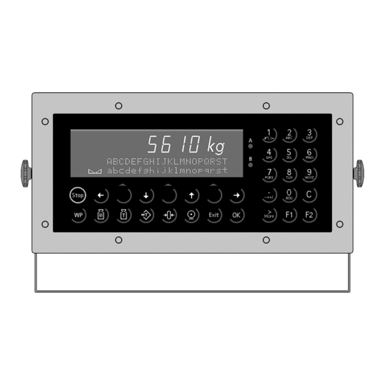
PR 5610 Installation Manual Function Description 2.4 Description of controls 2.4.1 Display Status indicator Dialogue keys Alphanumeric keys Indicator keys Function keys The Weight Display allows display of 7 digits for weight plus a decimal point. The unit can be selected as tons, kilograms, grams or lbs. -
Page 19: Keypad
Function Description PR 5610 Installation Manual 2.4.2 Keypad The symbols of the front-panel keys are given below: Indicator Indicator Description Description keys keys Gross weight is displayed while this B – Brutto, button is pressed ( Print-out German for Gross... -
Page 20: Operating Concept
PR 5610 Installation Manual Function Description 2.4.3 Operating concept 2.4.3.1 Operating via softkeys The operation is menu-guided. For this purpose, the instrument has a 'softkey’-functionality: Three 'softkeys' below the display marked by an upward-direction arrow correspond to the function described in the lower text display line. - Page 21 Function Description PR 5610 Installation Manual 2.4.3.3 Entering alphanumerical characters In the alphanumeric entry mode, a cursor blinks in the entry field. This mode is accessible by pressing a key from the alphanumeric keypad. The alphanumeric keys have got more than one assignment.
-
Page 22: Installing The Instrument And Options
PR 5610 Installation Manual Hardware Configuration NSTALLING THE INSTRUMENT AND OPTIONS Before starting any work, read chapter 1 "Safety hints, electrical protection class" and follow all hints! Further procedure: • Check the consignment: unpack all parts pertaining to the project. -
Page 23: Installing The Options
Hardware Configuration PR 5610 Installation Manual 3.2.1 Installing the options Board 1 is provided with 3 identical sockets (double row, 2*25 contacts) for options. The designation for the sockets (from left to right) is slot 1 ... 3. The plug-in card connections are taken identically from each slot to 16- pole terminal blocks. -
Page 24: Cable Gland And Connection
PR 5610 Installation Manual Hardware Configuration 3.2.3 Cable gland and connection All cables have to be fed into the instrument via glands to ensure protection according to IP 65. Cable diameters of 6...12 mm for PG13.5, 5...10 mm for PG11 and 4...8 mm for PG9 are suitable. The conductors are connected to screw terminals in the instrument. -
Page 25: Load Cell Cable / Cable Junction Box
Hardware Configuration PR 5610 Installation Manual 3.3.1 Load cell cable / cable junction box Connection of up to 8 load cells (650 Ohm) in 6-wire technique: • via cable junction box PR6130/.. with cable PR6135/.. The here mentioned cable colours are valid for SARTORIUS load cells of series PR 62 . - Page 26 PR 5610 Installation Manual Hardware Configuration Connection of one load cell in 4-wire technique: • Connect + Supply (3) to + Sense (4) and - Supply (6) to - Sense (5) at the terminal block. terminal LC connection description + Meas.
-
Page 27: External Pc Keyboard
Hardware Configuration PR 5610 Installation Manual 3.3.2 External PC keyboard The instrument is equipped with an alphanumeric front-panel keypad and a connection for a PC keyboard with DIN-plug (at the rear side of the housing). Both functions are equivalent. They can be used alternatively. -
Page 28: Bar Code Reader
PR 5610 Installation Manual Hardware Configuration 3.3.3 Bar code reader The DIN socket (at the rear side of the housing) can be used to connect a bar code reader instead of an external keyboard. Please check the power consumption of the bar code reader before connecting, it may not exceed 50 mA @ 5 V. -
Page 29: Rs 232 Built-In Interface
The interface can be used freely and can be configured e.g. for data transmission to a supervisory system, a remote display, a printer or an external Sartorius scale (xBPI). Technical data... - Page 30 PR 5610 Installation Manual Hardware Configuration 3.3.4.2 Remote display / remote terminal connection The builtin RS 232 interface can be used to connect the remote display PR 1627 or the remote terminal PR 1628. In [Serial port setup]-[Builtin RS232]-[Protocol] select [RemoteDsp], it has got some fixed parameters: Bits-7, Parity-Even, Stopbits-1.
- Page 31 PR 5610 Installation Manual 3.3.4.4 xBPI Platform connection RS232 The builtin RS 232 interface can be used to connect a Sartorius platform with xBPI protocol. For details please refer to the manual of the Sartorius platform. 3.3.4.5 xBPI Terminal connection RS232 The built-in RS 232 interface can be used to connect a Sartorius terminal with xBPI protocol.
-
Page 32: Options
PR 5610 Installation Manual Hardware Configuration 3.4 Options 3.4.1 PR 1713/04 Serial I/O The plug-in card contains 1x RS 232 and 1x RS 485/ 422, whereby only the RS 485 is galvanically isolated. Max. 3 cards PR 1713/04 can be used. The parameters of the RS 232 and RS 485/ 422 are adjusted by software configuration. - Page 33 Hardware Configuration PR 5610 Installation Manual PR1713/.. PR1713/04 SERIAL I/O U / U : RS232 ROW B U / U : RS422 / 485 +5Vi +5Vi ROW A +5Vi +5Vi S101 - 1 S101 - 3 S101 - 2 +5Vi...
- Page 34 PR 5610 Installation Manual Hardware Configuration Connection to the RS 232 interface (all protocols) Supervisory system/ PLC/ printer PR 1628/00 /24 remote terminal PR 1713/04 PR 1713/04 With XON/XOFF protocol, jumper RTS-CTS must be fitted.With hardware handshake, connect cables with the...
- Page 35 PR 5610 Installation Manual 3.4.1.1 xBPI Platform connection RS485 The PR 1713/04 RS 485 interface can be used to connect a Sartorius platform with xBPI protocol. For details please refer to the manual of the Sartorius platform. 3.4.1.2 xBPI Terminal RS485 The PR 1713/04 RS 485 interface can be used to connect a Sartorius terminal with xBPI protocol.
- Page 36 Receiver side: Modem confirmed: DCD is ok 5610 exspects: receive RxD PR 5610 with PR 1713/04 In case of hardware handshake: Connect lines with the opposite side (see above). The modem is controlled by the signals of the interface PR 1713/04 (see above).
- Page 37 Hardware Configuration PR 5610 Installation Manual Connection to an RS 485 bus (two-wire system) Supervisory system/ PLC PR 5610, slave 1 PR 5610, last slave Connection to an RS 485 bus (four-wire system) Supervisory system/ PLC PR 5610, slave 1...
-
Page 38: Pr 1713/05 Ram Extension
PR 5610 Installation Manual Hardware Configuration 3.4.2 PR 1713/05 RAM extension If higher RAM storage capacity is required (e.g. for Alibi Memory PR 1713/81), two chips of 512 kbyte can be fitted. The 2 empty sockets for the memory extension are located on board 2 beside the connector with the 4-pole power supply cable. -
Page 39: Pr 1713/06 Analog Output Card
Hardware Configuration PR 5610 Installation Manual 3.4.3 PR 1713/06 Analog output card Connecting method: 2-row 25-pin connector Terminal block A with 8 screw terminals 1 current output, voltage by use Number of outputs: of external resistor Gross, net weight or application... - Page 40 PR 5610 Installation Manual Hardware Configuration PR1713/0.. ROW A 0 (4)...20mA (Sig.GND) PR1713/06 Analog out 0 ... 20mA Analog signal, current output. The current is supplied directly from the terminals. 0 ... 10V Analog signal, voltage output. The voltage level corresponds to the voltage drop at the 500 Ohm resistor.
-
Page 41: Pr 1713/07 Analog I/O
Hardware Configuration PR 5610 Installation Manual 3.4.4 PR 1713/07 Analog I/O The instrument supports only 1 analog output (power consumption). The card (installation see 3.2.1) has 1 output like PR 1713/06 and 4 analog inputs. After coldstart, set-up in configuration mode is necessary. The output can be configured to 0/4...20 mA and gross or net weight. - Page 42 PR 5610 Installation Manual Hardware Configuration PR1713/.. PR1713/07 ANALOG OUT ANLOG I/O's ROW A 0 (4)...20mA (Sig.GND) ANALOG IN ROW B 50K0 50K0 250E CH 1 U(10V) I (20mA) S202-1 S201-1 50K0 50K0 250E CH 2 U(10V) I (20mA) S202-2...
-
Page 43: Pr 1713/08 Bcd Output
Hardware Configuration PR 5610 Installation Manual 3.4.5 PR 1713/08 BCD output option card for is preferably used in the slot 3 (installation see chapter 3.2.1), because otherwise plugs for This other cards are blocked. It does not make use of the terminal blocks A/B. - Page 44 PR 5610 Installation Manual Hardware Configuration Voltage supply for the output transistors 6 - Uext, ground potential 7 - GND Attention: avoid earth loops to GND! • Output: Each output line of the module PR 1713/08 works with common external voltage supply as reference potential and an open emitter output.
- Page 45 Hardware Configuration PR 5610 Installation Manual PR1713/.. PR1713/08 BCD out X104 1*10 1*10 1*10 1*10 1*10 X105 SIGN STSTI ERROR DAHOL J104 V1/V2 DESEXT Enab. & Uext J105 J103 Sartorius...
-
Page 46: Pr 1713/12 4 Opto Inputs / 4 Opto Outputs
PR 5610 Installation Manual Hardware Configuration 3.4.6 PR 1713/12 4 Opto inputs / 4 Opto outputs Max. 3 cards PR 1713/12 or PR 1713/15 can be used. The digital interfaces are passive (external supply is necessary) and have no common potential. - Page 47 Hardware Configuration PR 5610 Installation Manual PR1713/.. PR1713/12 ROW A Control I/O's Opto CONTROL OUT CH 1 CH 2 CH 3 CH 4 ROW B CONTROL IN CH 1 CH 2 CH 3 CH 4 Sartorius...
-
Page 48: Pr 1713/13 Dios Master
PR 5610 Installation Manual Hardware Configuration 3.4.7 PR 1713/13 DIOS master Only 1 card PR 1713/13 can be used. The DIOS card (digital I/O system as a simple Interbus-S master) is the connecting module for external I/O extension. Connecting method:... - Page 49 Hardware Configuration PR 5610 Installation Manual PR1713/.. PR1713/13 DIOS Master +5Vi +5Vi ROW A IBS-UART +5Vi Sig.GND +5Vi Sartorius...
- Page 50 PR 5610 Installation Manual Hardware Configuration 3.4.7.1 Units connected to the remote bus PR 1713/13 remote bus devices All Phoenix Interbus-S modules can be handled. Please, note the limitation to 256 I/Os. For e.g. PR 1720, 8 bytes are required, i.e. 192 I/O are still available in this case. A bus terminal (with local bus) is also a slave. Via jumper 5-9 at the output of a slave module, the master is informed that further modules in the bus will follow.
-
Page 51: Pr 1713/14 Ethernet
Hardware Configuration PR 5610 Installation Manual 3.4.8 PR 1713/14 Ethernet The card is plugged in slot 4 on board 2, (installation see chapter 3.2.2) Connecting method: 50 pole connector Terminal block with 5 screw terminals 10 Mbits/sec Transmission rate: Point to point... - Page 52 PR 5610 Installation Manual Hardware Configuration For further information refer to the User Manual delivered with the Ethernet card. Sartorius...
-
Page 53: Pr 1713/15 4 Opto Inputs / 4 Relay Outputs
Hardware Configuration PR 5610 Installation Manual 3.4.9 PR 1713/15 4 Opto inputs / 4 Relay outputs Max. 3 cards PR 1713/15 can be used. The digital interfaces are passive (external supply is necessary) and have no common potential. Connecting method:... - Page 54 PR 5610 Installation Manual Hardware Configuration The jumpers J102 (CH1), J105 (CH2), J108 (CH3), J111 (CH4) are set to A upon delivery (closing contact). To change to an 'opening contact' open A and close B by soldering. The jumpers J100, J101, J103, J104, J106, J107, J109, J110 are intended for special assembly and should not be altered.
-
Page 55: Pr 1713/17 6 Opto Inputs / 8 Opto Outputs
Hardware Configuration PR 5610 Installation Manual 3.4.10 PR 1713/17 6 Opto inputs / 8 Opto outputs Max. 3 cards PR 1713/17 can be used. The digital interfaces are passive (external supply is necessary) and have one common potential per input group and one common potential per output group. - Page 56 PR 5610 Installation Manual Hardware Configuration PR1713/.. PR1713/17 ROW A Control I/O's 6 / 8 CONTROL OUT ROW B B3V0 CONTROL IN B3V0 B3V0 B3V0 B3V0 B3V0 Sartorius...
-
Page 57: Pr 1721/11 Profibus Interface
PR 5610 Installation Manual 3.4.11 PR 1721/11 Profibus interface The Profibus interface PR 1721/11 is an option to be installed in slot 4 of PR 5610, see chapter 3.2.2. Communication protocols and syntax comply with the relevant bus standard. Connecting method:... -
Page 58: Pr 1721/12 Interbus Interface
PR 5610 Installation Manual Hardware Configuration 3.4.12 PR 1721/12 Interbus interface The Interbus interface PR 1721/12 is an option to be installed in slot 4 of PR5610, see chapter 3.2.2. Communication protocols and syntax comply with the relevant bus standard. -
Page 59: Pr 1721/14 Devicenet Interface
Hardware Configuration PR 5610 Installation Manual 3.4.13 PR 1721/14 DeviceNet interface The DeviceNet interface PR 1721/14 is an option to be installed in slot 4 of PR5610, see chapter 3.2.2. Communication protocols and syntax comply with the relevant bus standard. -
Page 60: Commissioning
PR 5610 Installation Manual Commissioning OMMISSIONING Commissioning can be done via the front panel keypad or through a terminal emulation program running on a PC or through a terminal (VT 100 compatible). After switching on for the fist time, the following error message can appear: The battery jumper has to be set (see chapter 0), this operation must be followed by a cold start (Cold) and clock (date and time) adjustment. -
Page 61: Configuration Data
Commissioning PR 5610 Installation Manual 4.1.2 Configuration data Adjusting the serial interface/ communication, field bus parameters. The configuration settings are also saved by command. The configuration settings are independent of CAL-switch, i.e. access to the configuration settings is always possible. -
Page 62: Display Elements And Controls
PR 5610 Installation Manual Commissioning 4.2 Display elements and controls Text display with 2x20 characters Weight value of the selected Alphanumeric keys weighing point Dialogue keys Indicator keys Function keys 4.2.1 Control signals Functions zero setting, tare / reset tare, weight display mode and print are allocated to the front-panel keys, i.e. -
Page 63: Operating Concept 'Commissioning
Commissioning PR 5610 Installation Manual 4.2.3 Operating concept ‘Commissioning’ The instrument configuration is done via keypad or, alternatively, with a terminal or a terminal program on a PC. The sections for calibration and configuration can be reached from the main menu via [Setup]. Gross weight display for calibration, if necessary, please: reset tare + set zero! Operating concept: The instrument is menu-guided with softkeys via keypad. -
Page 64: Main Menu
PR 5610 Installation Manual Commissioning 4.3 Main menu After connection to the power supply, the instrument shows the version number "PR 1713 Rel. 02.00.0" or the name of the application package (e.g. IBC Controller). The unit can be configured via the keypad or (after switching over) on a terminal. The operation of the unit is menu-guided. - Page 65 Commissioning PR 5610 Installation Manual 4.3.1.1 Setup menu Setup - Config Menu depends on application package, see resp. operating manual - Weighingpoints - WP A: - WP B: - Assign internal, liquid, user, GWT-Scale, x-BPIScale - Calib (for internal ADC) see chapter 4.3.1.2...
- Page 66 PR 5610 Installation Manual Commissioning 4.3.1.2 Internal ADC calibration tree WP X: Internal ADC - Assign internal, liquid, user, GWT-Scale, x-BPIScale - Calib - New - Reset all to default YES or NO - Set Fullscale 0.000100 ...<3000>... 9999900 <kg>, t, lb, g - Set Stepwidth <1>, 2, 5, select with [More] 10, 20, 50 , current stepwidth in ><...
- Page 67 Commissioning PR 5610 Installation Manual 4.3.1.3 Parameter tree Setup - Set Clock Time and Date - Serial Ports - Operator device at <Builtin RS232>, none, Slot 1 .. 3 RS485, Slot 1 ... 3 RS 232 (select) - Printer device at <none>, Builtin RS232, Slot 1 ..
-
Page 68: Boot Menu
PR 5610 Installation Manual Commissioning 4.3.2 Boot menu The Boot menu can be accessed by the following actions: Pressing during instrument power up Pressing , if [Setup]-[Software Parameter]-[Reset on stop+exit] = 1 or 5 s, a [Warm] start is not possible! Menu [Setup]-[Reboot] •... - Page 69 Commissioning PR 5610 Installation Manual [Cold] All programs and data loaded in RAM are erased: Depending on the application package these could be recipes, component data etc. Data in EAROM remain unchanged. Messages: The firmware checksum is tested. A cold start is carried out.
- Page 70 PR 5610 Installation Manual Commissioning 4.3.2.1 Weighing point initialization After [Erase], [Cold], [Warm] or power-on the weighing points will be initialized. This ensures that the physical weighing points are delivering valid weight values. If weighing points do not deliver valid data, an error message is generated.
- Page 71 During flashing various status messages are displayed: Subsequently, the boot menu with the following status line is displayed: Initialize PR 5610 with [Cold]. Flash erases the databanks of the instrument, therefore Erase is not necessary before Flash, to erase internal databanks.
-
Page 72: Weighing Point Assignment
PR 5610 Installation Manual Commissioning 4.4 Weighing point assignment It has to be differenciated between physical weighing points (e.g. internal ADC, xBPI scale) and logical weighing points (WP A, WP B and WP C). In menu [Setup]-[Weighingpoints]-[WP X]-[Assign] the physical weighing point... -
Page 73: Error Messages On The Weight Display
Commissioning PR 5610 Installation Manual Now [Calib] for the internal ADC can be accessed. 4.4.1 Error messages on the weight display The internal ADC and the external weighing points can generate error messages to appear on the weight display. If more than 1 weighing point has been assigned, the selection is done with . -
Page 74: W&M Parameter
PR 5610 Installation Manual Commissioning 4.4.2 W&M Parameter For all weighing point types a W M parameter can be set individually (see chapter 4.3.1.1). & The parameter can only be set / changed, if the CAL switch is open. The following selections are possible (the default data are displayed) :... -
Page 75: Calibration, Internal Adc
Commissioning PR 5610 Installation Manual 4.5 Calibration, internal ADC Calibration of the internal weighing point by weights or mV/V can be realized via keypad or terminal / PC. Calibration data are protected by the CAL-switch, which has to be sealed in legal for trade applications. -
Page 76: Select Weighing Point
PR 5610 Installation Manual Commissioning 4.5.4 Select weighing point The selection of the weighing point is carried out by [Setup]-[Weighingpoints]. Change weighing point with and select calibration of the displayed weighing point with [Calib]. The calibration menu with the selections [New], [Modify] or [Param] is displayed. -
Page 77: Set Full Scale
Commissioning PR 5610 Installation Manual 4.5.7 Set full scale Enter numeric values for FSD with or without decimal point. Change weight unit with , confirm with Acknowledgement of full scale. 4.5.7.1 Resolution magnifier The weight display can be switched to 10-fold during calibration with (toggle function). -
Page 78: Set Full Scale Deflection (Span)
PR 5610 Installation Manual Commissioning Acknowledgement after pressing Continue with 4.5.10 Set full scale deflection (span). 4.5.10 Set full scale deflection (span) The choices [Load], [mV/V] and [Data] for the span entry are displayed. [Load] Select [Load], if the scale is to be loaded with a known weight. -
Page 79: Calculate Test Value
Commissioning PR 5610 Installation Manual Enter the local gravity from 9.00000 to10.00000; confirm with Select the hysteresis error with [specified] or [not specified] with ; confirm with . The choice [specified] is followed by the entry of the correction values, which is jumped over for [not specified]. -
Page 80: Exit Calibration
PR 5610 Installation Manual Commissioning Automatic return to the selection menu for the calibration with the indication, that the calibration has been changed. 4.5.12 Exit calibration Finish the calibration with Display of the choices [Save] and [Undo]. [Save] Store new calibration data with [Save]. -
Page 81: Set Parameters
Commissioning PR 5610 Installation Manual FSD is smaller than the calibrated weight (span). 4.5.13 Set parameters [Param] Select [Param] to enter the measuring parameters. Enter measure time with numeric keys from 50 to 1000 ms; confirm with Select choices [on] or [off] for analog filter for the measuring signal with ;... - Page 82 PR 5610 Installation Manual Commissioning Enter the overload range > FSD with numeric keys from 0 to 9999999 d; confirm with Enter minimum weight for print-out with numeric keys from 0 to 9999999 d; confirm with Select operating mode multi range scale (max. 3 ranges) [on] or [off] with ;...
-
Page 83: Configuration For 'Liquid', 'User', 'Gwt-Scale', 'Xbpi-Scale
Commissioning PR 5610 Installation Manual 4.6 Configuration for 'liquid', 'user', 'GWT-Scale', 'xBPI-Scale' The physical weighing points can be assigned to the logical weighing points (WP A, WP B), see chapter 4.4. After the assignment, the physical weighing points have to be configured. The configuration differs according to the scale type. -
Page 84: Weighing Point Function Gwt-Scale
PR 5610 Installation Manual Commissioning Exit configuration and store data with [Yes]. With [No] the data remain unchanged. Automatic return to the weighing point selection menu. 4.6.2 Weighing point function GWT-scale With the GWT-scale the update time must be defined and with fieldbus applications additionally a slave address must be defined. -
Page 85: Weighing Point Function Xbpi-Scale
; confirm with . [Remote] has to be selected for an ISI-terminal. The tare function is not carried out in the PR 5610. [Local] has to be selected for a xBPI-platform. The tare function is carried out in the PR 5610. -
Page 86: Xbpi Scale
4.7 xBPI Scale The PR 5610 can communicate with a Sartorius scale or platform via the xBPI protocol. The serial interface option PR 1713/04 has to be installed or the serial port Builtin can be used. For applications written in IEC 61131 an additional set of functions is described in a separate documentation. -
Page 87: Xbpi Serial Port Setup
Commissioning PR 5610 Installation Manual 4.7.1 xBPI Serial port setup In menu [Setup]-[Serial Ports]-[Serial port setup] the port connected to the Sartorius scale / platform has to be defined. Select with the interface module and confirm with If currently a protocol is running, it will be stopped and shown. -
Page 88: Xbpi Platform Configuration
4.7.3 xBPI Platform configuration The XBPI platforms have got so-called specification blocks to select the different operating modes (Single range, multi range etc.). Select [Setup]. The PR 5610 is loading the parameters from the Sartorius platform. Error message: No communication with xBPI scale Select [Select]. -
Page 89: Xbpi Scale Parameters
In menu [Setup]-[Weighingpoints]-[WP X:xBPIScale]-[Setup]-[Config] the scale parameters are set. Before entering this menu, the protocol (see chapter 4.7.1) and the WP (see chapter 4.7.2) have to be defined and the communication between the instrument and the Sartorius scale or platform must be in active staus. Select [Setup]. -
Page 90: Xbpi Scale Parameter Tables
PR 5610 Installation Manual Commissioning 4.7.5 xBPI Scale parameter tables In the following tables the parameters to be entered under [Setup]-[Weighingpoints]-[WP X:xBPIScale]- [Setup]-[Config]-[Scale], ... [Config]-[Appl] and ... [Config]-[Interf] are listed. Depending on the scale not all not valid for scale items can be selected. - Page 91 Commissioning PR 5610 Installation Manual [Appl] "Application Tare :" "Weight unit 2 :" "Weight unit 3 :" "Accessible " "gramm g" "gramm g" "Blocked " "kilogram kg" "kilogram kg" "Carat ct" "Carat ct" "Number of ranges :" "Pound lb" "Pound lb"...
-
Page 92: Xbpi Scale Setting Deadload
In menu [Setup]-[Weighingpoints]-[WP X:xBPIScale]-[Setup]-[Calib] the deadload can be set. For GWT scales deadload preload the term is used, for Sartorius scales the term is used. After selecting [xBPI Scale Setup], the instrument is loading the parameters from the Sartorius scale. -
Page 93: Xbpi Calibration With Internal Weight
Before entering this menu, the protocol (see chapter 4.7.1) and the additional WP (see chapter 4.7.2) have to be defined and the communication between the instrument and the Sartorius scale or platform must be in active staus. -
Page 94: Xbpi Calibration With Automatic Weight Recognition
PR 5610 Installation Manual Commissioning The previously stored user weight is shown, the weight can be altered and confirmed with The target weight for calibration is shown, the calibration weight has to be placed on the scale. The deviation is shown. After selecting [Accept] the instrument returns to menu [xBPI Scale adjust]. -
Page 95: Configuration Of Non-Weighing Point Related Parameters
Commissioning PR 5610 Installation Manual 4.8 Configuration of non-weighing point related parameters The configuration of all parameters, which do not belong to the internal weighing point, is divided into several sections (see chapter 4.3.1.3 Parameter tree). 4.8.1 Set clock (date and time) For adjusting date and time, select [Setup]-[Set Clock]. - Page 96 PR 5610 Installation Manual Commissioning Setting the interface parameters [Serial port setup] Selection of the built-in interface [Builtin RS232], [Slot 1…3 RS485] or [Slot 1…3 RS232] with ; confirm [Protocol] with Protocols available are: XON/XOFF software handshake 3964R-slv Siemens S5 Dust slave...
-
Page 97: Software Parameters
Commissioning PR 5610 Installation Manual Possible error message User tried to select the parameters of e.g. Built-in RS232, which has been assigned to printer device or operator device (parame- ters are already fixed). 4.8.3 Software parameters Basic parameters are defined in the section [Setup]-[Software Parameter]. - Page 98 PR 5610 Installation Manual Commissioning 4.8.3.5 Tare key Select the tare key function [enabled] or [disabled] with ; confirm with 4.8.3.6 Set zero key Select the set zero key function [enabled] or [disabled] with ; confirm with 4.8.3.7 Quit in mainlevel If the instrument is configured via terminal or PC the Q command can be used to terminate the communication.
-
Page 99: Fieldbus Parameter
Commissioning PR 5610 Installation Manual 4.8.3.11 Lines per Recipe With lines per recipe the maximum number of component lines in a recipe is defined. Enter the number of requested lines per recipe form [1] to [255] with numeric keys; confirm with 4.8.3.12 Recipe simulation... -
Page 100: Licence Setup
For all protocols the [Scale- interface] has to be set. Select the operating mode [enabled] for a standard interface fieldbus - PR 5610 with 8 Bytes and [disabled], if a IEC 61131- application program is handling the fieldbus; confirm with Leaving the menu Leaving the fieldbus configuration menu. -
Page 101: Show Board Number
Commissioning PR 5610 Installation Manual After [Delete] a 7 digit licence number can be entered and con- firmed with . For a valid number the message 'PR17XX/XX disabled' is displayed. Otherwise the message 'wrong Licence number' is displayed. Leave the menu with Prompt at leaving the menu. -
Page 102: I/O Slots
PR 5610 Installation Manual Commissioning 4.8.10 I/O Slots The type of interface installed in slot 1 ... slot 4 is shown. Enter with , depending on the type of interface different information is given Example: PR 1713/12 is installed in slot1, with @ the task no. is shown. -
Page 103: Enable Download
Commissioning PR 5610 Installation Manual 4.8.12 Enable download This menu appears only if [Setup]-[Software Parameter]-[Software download] is set to [protected by setup]. Select access with The download is enabled, menu can be left with If the [Software download] is set to [protected by setup] and [Download enabled] is not active, an error message appears on the PR 1750 (for Rel. -
Page 104: Modbus / J-Bus Protocol
A reply is sent on each faultless command, the answertime amounts to 4ms (typical) and 8 ms (max.) at 9600 baud. A faulty command received by PR 5610 (e.g. parity error in the data or CRC error) is ignored. In this case, no reply is sent. -
Page 105: Function 1 Or 2: Read N Bits
Commissioning PR 5610 Installation Manual 4.10.2 Function 1 or 2: Read n bits Command Device Function Address of Number of CRC 16 address number 1st bit bits 1 byte 1 byte 2 bytes 2 bytes 2 bytes Range 1...127 1, 2 0,8,16... -
Page 106: Function 5: Write A Bit
PR 5610 Installation Manual Operation with Terminal 4.10.4 Function 5: Write a bit Command Device Function Bit address Bit value always 0 CRC 16 address number 1 byte 1 byte 2 bytes 1 byte 1 byte 2 bytes Range 0...127 0...32760... -
Page 107: Function 8: Diagnosis
Commissioning PR 5610 Installation Manual 4.10.6 Function 8: Diagnosis Command Device Function Sub- any value CRC 16 address number function 1 byte 1 byte 2 bytes 2 bytes 2 bytes Range 1...127 This function is used for communication checking. Only sub-function 0 is supported. -
Page 108: Function 16: Write N Successive Words
PR 5610 Installation Manual Operation with Terminal 4.10.8 Function 16: write n successive words Command Device Function Address of Number Number of Value of CRC 16 address number 1st word of words bytes words 1 byte 1 byte 2 bytes... -
Page 109: Modbus / J-Bus Addresses
Commissioning PR 5610 Installation Manual 4.10.10 MODBUS / J-BUS Addresses Gross weight 1st byte (MSB) Gross weight 2nd byte Gross weight 3rd byte Gross weight 4th byte (LSB) 560 561 562 563 564 565 566 567 568 569 570 571 572 573 574 575... -
Page 110: Commissioning With Terminal
• The interface parameters of the PC/terminal have to be set to the same as in the instrument. 5.1.1 Connecting PR 5610 to PC The PC is connected with a directly connected cable (Rx-Tx not crossed) to the Builtin RS 232 interface . -
Page 111: Main-Command-Level Menu Structure
Commissioning with Terminal PR 5610 Installation Manual 5.1.2.2 Switch-on messages The terminal output after instrument switch-on is the initialization message, followed by the main screen: Instrument and version message, date/ time, main menu, see chapter 5.1.3. 5.1.2.3 Terminate terminal emulation program Before switching on the PC or before closing the terminal emulation program, return to the main menu. - Page 112 PR 5610 Installation Manual Commissioning with Terminal 5.1.3.1 Menu structure (tree) With configuration on a serially connected terminal, the following menu is valid: Main-Command-Level - C Configuration Configuration data - D Set date Enter date - T Set time Enter time...
-
Page 113: General Operating Notes
Commissioning with Terminal PR 5610 Installation Manual 5.1.4 General operating notes English expression All terms used in the masks are in English. In the description, the relevant or display text is shown in a different font. A submask can be left on several ways, which are displayed in the lower mask area, e.g. -
Page 114: Configuration
PR 5610 Installation Manual Commissioning with Terminal 5.2 Configuration Configuration Main-Command-Level Calling up mask is from the , by pressing key [C]. PR1713 Rel. 03.12. 20.05.2004 09:05 Configuration Mo 05.July 2004 13:06:16 D Set date T Set time C Change serial port parameter... -
Page 115: Set Time
Commissioning with Terminal PR 5610 Installation Manual 5.2.2 Set time Configuration Mo 05.July 2004 13:06:16 D Set date T Set time ..Enter new time [13:06:16]: • Press key [T] • The following message is displayed: Enter new time [13: 06:16]: •... - Page 116 If elements appear in brackets on the screen, selection is not possible. ⇒ A PR 5610 can be equipped with max. 7 serial interfaces. For a survey, see chapter 5.2.3.1. ⇒ Dependent of selected protocol (and interface), defined default settings are made by the system.
-
Page 117: Entry Of Software Licence Numbers
Commissioning with Terminal PR 5610 Installation Manual 5.2.4 Entry of software licence numbers License configuration Configuration Calling up mask is done from sub-menu by pressing key [L]. PR1713 Rel. 03.12 20.05.2004 09:05 License Configuration Mo 05.July 2004 09:31:51 Boardnumber: 8409060... -
Page 118: Entry Of Software Parameters
PR 5610 Installation Manual Commissioning with Terminal 5.2.5 Entry of software parameters Calling up mask Set software configuration is from sub-menu Configuration by pressing key [S]. PR1713 Rel. 03.12 20.05.2004 09:05 Software Configuration Mo 05.July 2004 09:31:51 Language :English Frontkey timeout... -
Page 119: Fieldbus Parameter
Commissioning with Terminal PR 5610 Installation Manual 5.2.6 Fieldbus parameter Set fieldbus configuration Configuration Calling up mask is from sub-menu by pressing key [F]. PR1713 Rel. 03.12 20.05.2004 09:05 Interbus-S Fieldbus Configuration Calculate actualization interval: 1000 / (15 + number of bytes+ 0.3 x number... -
Page 120: Entry Of User-Defined Units
PR 5610 Installation Manual Commissioning with Terminal 5.2.7 Entry of user-defined units PR1713 Rel. 03.12 20.05.2004 09:05 Configuration Mo 05.July 2004 13:06:16 U Set units F Set fieldbus configuration E Exit Enter new units : u1u2u3u4u5u6u7u8 For use of IEC 61131 firmware functions MAKE_WEIGHT and SET_WEIGHT_UNIT, 8 different units can be defined. -
Page 121: Weighing Point Mask
Commissioning with Terminal PR 5610 Installation Manual 5.3 Weighing point mask Weighingpoint Main Command Level Calling up mask is done from the by pressing key [W]. PR1713 Rel. 03.12 20.05.2004 09:05 Weighingpoint Max= 3000kg 0001kg A < > N 0050kg... -
Page 122: Weighingpoint Assignment
Liquid counter (internal) user Customer-specific weighing point GWT Scale PR 1720 or PR 5610 / PR 1713 (via Interbus) Sartorius scale xBPI Scale • After entering [↵] the weighing point type for B can be selected using the two cursor keys [↑] and [↓]. The actually selected weighing point is highlighted by inverse display. - Page 123 Commissioning with Terminal PR 5610 Installation Manual 5.4.1.1 Calling up and display of the weighing point calibration mask ♦ Calling up weighing point calibration mask Calib/Config • Weighing point selection is by means of the cursor keys [↑] and [↓]. The actually selected weighing point is highlighted by inverse display.
-
Page 124: Saving The Weighing Point Parameters In Earom
PR 5610 Installation Manual Commissioning with Terminal 5.4.1.2 Leaving the weighing point calibration mask When leaving the mask, decision what shall be done with the entered weighing point parameters must be made. Leaving the mask is always started with command •... -
Page 125: Internal Adc, Parameters
Commissioning with Terminal PR 5610 Installation Manual 5.5 Internal ADC, parameters The editing functions for parameter entry are described in the first sub-section, the individual parameters are described in the following sub-sections. 5.5.1 Editing functions for parameter entry Weighing point selection is done with the cursor keys [↑] and [↓]. The selected weighing point is highlighted by inverse display. -
Page 126: Filter: Analog Filter
PR 5610 Installation Manual Commissioning with Terminal 5.5.2 Filter: Analog Filter Select between filter = on or no filter = off. The anlog filter (low-pass) has got a 2nd-order Butterworth characteristic with a cutoff frequency of 2Hz. The filter is located before the ADC and should be set to on. -
Page 127: Automatic Zero Tracking
Commissioning with Terminal PR 5610 Installation Manual 5.5.7 Automatic zero tracking In case of change of the empty scale (hopper weight) e.g. due to loss (dead load reduction) or formation of slag (dead load increase) by only a very low amount, automatic zero tracking ensures that the scale is reset to zero automatically. -
Page 128: Maximum Permissible Overload: Overload
PR 5610 Installation Manual Commissioning with Terminal Overload 5.5.14 Maximum permissible overload: Entry is in d, permissible range 0d to 9999999d no p below 5.5.15 Min. weight limit for print-out: Entry is in d, permissible range 0d to 9999999d Stepwidth 5.5.16 Stepwidth (scale divisions):... -
Page 129: Weighing Point Calibration
Commissioning with Terminal PR 5610 Installation Manual 5.6 Weighing point calibration During calibration, the relationship of display and measured variable (weight) is determined. This relation is determined by the two entries • Deadload Deadload (weight of the empty scale ) and •... -
Page 130: Editing Functions For Parameter Entry
PR 5610 Installation Manual Commissioning with Terminal 5.6.2 Editing functions for parameter entry ♦ Weighing point selection Weighing point selection has to be done before calling up this weighing point calibration mask: Weighing point selection is by means of the two cursor keys [ ↑ ] and [ ↓ ]. Thereby, the actually selected weighing point is highlighted by inverse display. -
Page 131: Default Span
Commissioning with Terminal PR 5610 Installation Manual 5.6.4 Default span Use the default span value Return to FiXed X to set fixed span Press key [X] for taking over the default span. To avoid operator errors, the displayed prompt must be replied... - Page 132 PR 5610 Installation Manual Commissioning with Terminal The system offers the following replies: Unload and hit 0 unload the scale and set the zero S to skip skip zero setting Q to quit leave the calibration without doing anything E to end...
- Page 133 Commissioning with Terminal PR 5610 Installation Manual • X to set fixed span Set the fixed span If the calibration cannot be finished correctly for any reason, press key [X]. To avoid operator errors, a [Y/N] prompt is displayed and must be replied with Yes/ No: The system executes the command.
-
Page 134: Weighing Point Calibration Without Weights
PR 5610 Installation Manual Commissioning with Terminal Unload/ Load The following command line is displayed in the mask: Calibration by weight Unload and hit O or S to skip, E to end, X to set fixed span, P to print... - Page 135 Commissioning with Terminal PR 5610 Installation Manual • Deadload: calculation of the equivalent input voltage in mV/V The input voltage equivalent to the deadload in mV/V is calculated as follows: deadload (weight) load cell sensitivit CAvr [mV/V] deadload [mV/V] load...
- Page 136 PR 5610 Installation Manual Commissioning with Terminal Keys Select item with cursor up/down/left/right Change with +/- Return to FiXed, Set Fullscale, Calibrate by Weight or Millivolts E Exit calibration Calibration is finished. The data must be saved: Proceed as described in points 9. and 10. of the 'Weighing point calibration procedure'.
-
Page 137: Error Messages In The Calibration Menu
Commissioning with Terminal PR 5610 Installation Manual 5.6.8 Error messages in the calibration menu no standstill no standstill was reached during calibration. value is invalid the parameter is too high or too low. Proposal of the highest permissible value with: setting max.. -
Page 138: Liquid Counter
PR 5610 Installation Manual Commissioning with Terminal 5.6.9 Liquid counter With a liquid counter, weight value measurement is volumetric. The material flow passes through a flow counter, which generates one/several pulse(s) per defined flow rate. These specific data are entered during configuration of the liquid counter. -
Page 139: Customer-Specific Weighing Point (User)
• Permitted batch modes as standard weighing point • Batching cycle 50 msec • Power failure behavior Batching sequence provided, as standard • Save the definition data in the PR 5610 RAM. Data must be re-entered after COLD start. Sartorius... - Page 140 PR 5610 Installation Manual Commissioning with Terminal PR1713 Rel. 03.12 20.05.2004 09:05 Configuration of WP B Type :user W & M none Fullscale 1000kg Stepwidth Overload Minwgt Scale Weight Scale Counts 1 cnt Update Time 300 ms SPM marker address The parameters can be selected using the two cursor keys [ ↑...
-
Page 141: Gwt Scale
PR 5610 Installation Manual 5.6.11 GWT Scale The weight is read directly from the PR 1720 or PR 5610. By means of a customized IEC 61131 program, the weight value (read out with GET_WEIGHT) can be made available on the alphanumeric display. -
Page 142: Sartorius Scale (Xbpi)
PR 5610 Installation Manual Commissioning with Terminal 5.6.12 Sartorius scale (xBPI) The weight is read from a Sartorius scale via the xBPI protocol. Configuration of WP B The weighing point is indicated in the mask header: PR1713 Rel. 03.12 20.05.2004 09:05... -
Page 143: Sub-Menu Service
Print out all configuration data. • Leave sub-menu Service E Exit As no data can be changed, return is direct to the main menu without additional prompts. 5.7.1 Available memory in PR 5610 Show available memory Service Calling up mask is from sub-menu by pressing key [M]. -
Page 144: Show Hardware Configuration
PR 5610 Installation Manual Commissioning with Terminal The following information is displayed in the mask • bytes physical memory bank 1 Standard memory [bytes] • bytes physical memory bank 2 Memory Ext. PR 1713/05 [bytes] • bytes total physical memory Max. - Page 145 Commissioning with Terminal PR 5610 Installation Manual • E Exit Leave sub-menu 'Test Input/Output' ⇒ After leaving this mask (E), return is to sub-menu 'Service'. Only then all outputs set during testing are reset and the output commands of the PLC programs are retransmitted to the process.
- Page 146 PR 5610 Installation Manual Commissioning with Terminal 5.7.3.2 Analog input / output module testing The test can be executed for PR 1713/06 and PR 1713/07. PR1713 Rel. 03.12 20.05.2004 09:05 Test PR1713/06 Slot-Number 2 Mo 06.May 2002 09:31:51 Current Analog Output Value: Dec: 75.0% = 15.000 mA (9FAD)
- Page 147 Commissioning with Terminal PR 5610 Installation Manual 5.7.3.3 Digital module testing The test can be executed for PR 1713/12, PR 1713/15 and PR 1713/17. PR1713 Rel. 03.12 20.05.2004 09:05 Test PR1713/12 Slot-Number 3 Inputs: I1= 1 I2= 0 I3= 1...
-
Page 148: Printing All Configuration Data
PR 5610 Installation Manual Commissioning with Terminal 5.7.3.4 Test BCD-Output The screen for testing PR 1713/08 is displayed, if the card is detected in the system. The actual input- and output values are displayed binary and for the output also in hex- and decimal notation. Single output bits may be changed by 'Set Bit' or 'Reset Bit'. -
Page 149: Iec 61131 Operating Level
Commissioning with Terminal PR 5610 Installation Manual 5.8 IEC 61131 operating level The operating level is required for testing (user-specific) IEC 61131 programs. Calling up Commandline operating level is done from the Main-Command-Level by pressing key [L]. • > An empty screen with prompt character ' ' is displayed. -
Page 150: Technical Data
PR 5610 Installation Manual Technical Data ECHNICAL DATA The characteristical data are valid after a min. warm-up time of 60 minutes (reference temperature 23° C). Values specified without tolerances are average values and are only used for information. 6.1 Analog part, A/D conversion Principle DC. -
Page 151: Ec-Declaration Of Conformity
Anschrift: Germany Product name: PR 1713, PR 5610, PR 5710 System Weighing Controller Produkt Name: This product complies with the following regulations of the Directives of the European Community: Das Produkt stimmt mit folgenden Vorschriften der Richtlinien der Europäischen Gemeinschaft überein:... -
Page 152: Certificate Of Type Approval Pr 1713, Pr 5610 (X5), Pr 5710 (X6)
PR 5610 Installation Manual Technical Data 6.1.6 Certificate of type approval PR 1713, PR 5610 (X5), PR 5710 (X6) For a scale based on the instrument, the certificate of type approval no. D99-09-039 by Physikalische- Technische Bundesanstalt (PTB) for non-automatic weighing machines (EN45501) has been issued, i. e. the instrument meets the prerequisites for approval by the local authorities in all countries of the European community. -
Page 153: Location Of Seals Pr 1713, Pr 5610 (X5)
Technical Data PR 5610 Installation Manual 6.1.7 Location of seals PR 1713, PR 5610 (X5) We recommend using a fibre-tipped pen with water and ultraviolet light resistant ink, e. g. type Staedtler PANCOLOR EAM 4007817-32116. for the inscription on the labels. This pen is available under service code no. -
Page 154: Location Of Seals Pr 5710 (X6), Foil Pr 5610 (X5)
PR 5610 Installation Manual Technical Data 6.1.8 Location of seals PR 5710 (X6), foil PR 5610 (X5) Sartorius... -
Page 155: Digital Part
Technical Data PR 5610 Installation Manual 6.2 Digital part Processor: MC68331 with 16 MHz SRAM: 2x 128k8 (max. 2x 512k8) in SMD Optional: PR 1713/05 2x 512k8 for plugging into DIP FLASH: 2x 512k8 EAROM: 2k8 SPI 6.2.1 Backup battery... -
Page 156: Environmental Effects
PR 5610 Installation Manual Technical Data 6.3 Environmental effects 6.3.1 Power voltage sags Power voltage sags >10 ms at 100% sag, without instrument reaction >20 ms at 50% sag, " " " " 6.3.2 Environmental conditions Temperature range Ambient temperature operation -10... -
Page 157: Mechanical Data
Technical Data PR 5610 Installation Manual 6.4 Mechanical data 6.4.1 Construction type All metal housing of stainless steel. Protection class IP 65. 6.4.2 Dimensions Housing Dimensions Width 288 mm Height 144 mm Depth 130 mm (135 mm incl. blind plugs) 6.4.3 Connections... -
Page 158: Field Bus Options
PR 5610 Installation Manual Technical Data 6.5 Field bus options 6.5.1 Interbus-S/ Profibus-DP/ DeviceNet INTERBUS Standard DIN 19258 INTERBUS Baudrates [kBps] 500 [kBps] Knode width 8 bytes or 4 words Process data Parameter data remote digital bus unit with I/O... -
Page 159: Gsd File For Pr 1721 Profibus Dp
Technical Data PR 5610 Installation Manual 6.5.2 GSD file for PR 1721 Profibus DP Use our website at Internet address http://www.global-weighing.com for loading the GSD file GWT_00C3.GSD for PR 1721, or generate file GWT_00C3.GSD by entry of the following listing (the comments behind the semi-colon are optional): ;=======================================================================... -
Page 160: Eds-File For Pr 1721 Devicenet
PR 5610 Installation Manual Technical Data 6.5.3 EDS-file for PR 1721 DeviceNet EDS file pr1713.eds can be generated by entry of this listing or copied under Internet address http://www.global-weighing.com $ DeviceNet Manager Generated Electronic Data Sheet [File] DescText = "PR1713";... -
Page 161: Annex
COLD start All programs and tables loaded in the RAM are erased Microsoft communication protocol (Dynamic Data Exchange) EW protocol The serial communication protocol for SARTORIUS batching systems, version V1/ V2/ V3 Flash Program loading (also parts) Full scale deflection... -
Page 162: Index
PR 5610 Installation Manual Index NDEX Analog input / output ..........13 Editing functions in masks ........110 Analog input / output module testing ....... 143 EN61010 ..............5, 6 Analog output............13, 36 Erase................66 Analog output module..........143 Error messages............ - Page 163 Software download............. 95 physical weighing point..........69 Software parameters ..........115 Power supply ..............6 Span................126 Power supply PR 5610/X1 ........... 7 Standstill detection ........... 123 PR 1627 .............. 27, 113 Stepwidth..........74, 125, 135, 137 PR 1628 .............. 27, 113 Stop + Exit..............
- Page 164 PR 5610 Installation Manual Index Weighing point initialization........67 Weight limit ............. 125 VDE 0411 ..............5, 6 WIN-Terminal ............107 Volumetric weight measurement ....... 136 xBPI ..............28, 32 W&M..............113, 125 xBPI Scale..............83 W&M mode..............79 W&M Parameter............71 Warm................
- Page 165 Sartorius Hamburg GmbH Meiendorfer Straße 205 22145 Hamburg, Germany Tel +49.40.67960.303 Fax: +49.40.67960.383 www.sartorius.com Sartorius Hamburg GmbH All rights are strictly reserved Printed in Germany Reproduction or divulgation in any form whatsoever is not permitted without written from the copyright owner.
Need help?
Do you have a question about the PR 5610 and is the answer not in the manual?
Questions and answers