
Subscribe to Our Youtube Channel
Summary of Contents for Epilog Mini Series
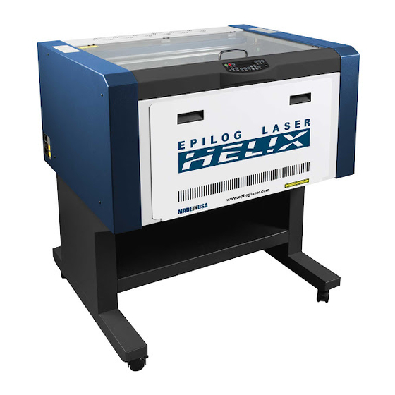
- Page 1 Laser Alignment Step-By-Step for the Epilog Mini and Helix Manufactured From 2010 to Current (8000 Model)
- Page 2 • You are experiencing ‘Fading’ in one of the corners of the table. • You are losing power in certain positions on the table. • You have replaced a Laser Tube. • You have replaced a Mirror or Optic. Laser Alignment, Epilog 8000 Series...
-
Page 3: Things You Will Need
Things You Will Need • Black Alignment Target • Masking Tape • Phillips Head Screwdriver - #2 • Allen Wrench - 3/32” • Safety Glasses Laser Alignment, Epilog 8000 Series... -
Page 4: Remove Panels
Always wear safety glasses when the panels have been removed and always stand away from the exposed sides when firing the laser. Tip: Any Safety Glasses will work. You don’t need special ‘laser’ glasses for the CO2 Laser. Laser Alignment, Epilog 8000 Series... - Page 5 Table Positions To make the process easier to understand the corners of the engraving area will be labeled as follows: (Rear) Pos 1 Pos 3 (Table) Pos 2 Pos 4 (Front) Laser Alignment, Epilog 8000 Series...
- Page 6 There are 3 mirrors used to adjust the laser beam. These mirrors are shown in the picture below. Mirror 2 Mirror 3 Mirror 1 Tip: The Mirror Numbers match the Table Positions. When adjusting alignment on Position 1 you should only use Mirror 1 and so on. Laser Alignment, Epilog 8000 Series...
-
Page 7: Before You Start
If you are performing this alignment because you have been sent a new Laser Tube. Please sure that protective tape covering the end of the new Tube been removed before attempting to fire the laser. Laser Alignment, Epilog 8000 Series... - Page 8 Pre-Alignment Procedure Overview For engravers made after 2010. Power On Fire the Place Position Align Begin and Enter Laser, Target and Pointer to Laser Alignment Make A Tape Carriage Burn Mark Alignment Mode Burn Laser Alignment, Epilog 8000 Series...
- Page 9 Place Target & Tape Place Alignment Target in Lens Carriage. Place Masking Tape on Target. Laser Alignment, Epilog 8000 Series...
- Page 10 • Power the engraver on and wait for “Job:” to appear on the display. • Press the “Maint” button on the Keypad to enter the Maintenance Menu. • Use the Arrow keys to navigate to “Align Laser”. And press “GO”. JOB: Laser Alignment, Epilog 8000 Series...
- Page 11 Once in “Align Laser” mode, the X and Y axis will release. Open reach inside of the engraver and pull the Lens Carriage to Position #4. I-Beam Table I-Beam Laser Alignment, Epilog 8000 Series...
- Page 12 Be sure that both the Glass Door and the Front Door are firmly closed. When ready, press and hold the Up Arrow key for a few seconds. Release when you notice a burn appear on the target. Press Up to Fire Laser Alignment, Epilog 8000 Series...
- Page 13 Turn On Red Pointer • Press the “Pointer” button to turn on the Red Dot Pointer Red Dot On Laser Alignment, Epilog 8000 Series...
- Page 14 The Red Dot Pointer is in the rear of the machine, mounted to the right end of the laser tube. Pointer Adjustment Screws Laser Alignment, Epilog 8000 Series Next Tip: Small adjustments can make large changes! Always make Very Small Adjustments.
- Page 15 Align the pointer Which Adjustment Screws to Use Clockwise Laser Alignment, Epilog 8000 Series Next...
- Page 16 Align the pointer Which Adjustment Screws to Use Clockwise Laser Alignment, Epilog 8000 Series Next...
- Page 17 Align the pointer Which Adjustment Screws to Use Counterclockwise Laser Alignment, Epilog 8000 Series Next...
- Page 18 Once the Red Pointer is aligned with the Burn Mark in Position 4 than the Pre-Alignment is complete and your Red Pointer will represent the path of the cutting beam in the rest of the engraver. Laser Alignment, Epilog 8000 Series...
- Page 19 Laser Alignment Overview Align Laser Align Laser Disable Axis in Position 1 in Position 2 Check Align Laser Run Test Alignment in Position 3 Complete Alignment Laser Alignment, Epilog 8000 Series...
- Page 20 An accurate alignment is all about repetition. Repeat the alignment steps until you can get between positions 1, 2 and 3 with very minimal movement of the red dot pointer. The more often you repeat, the more accurate it becomes! Laser Alignment, Epilog 8000 Series...
- Page 21 Disable Axis • On the Engraver press “X/Y Off”. • Press “Go” to confirm. • You may now move the lens carriage freely by hand. Laser Alignment, Epilog 8000 Series...
- Page 22 Align Position 1 Move the Lens Carriage to Position 1 I-Beam Table Laser Alignment, Epilog 8000 Series...
- Page 23 Mirror 1 to move the pointer to the center of the alignment target Laser Alignment, Epilog 8000 Series...
- Page 24 Align Position 2 Move the Lens Carriage to Position 2 Table I-Beam Laser Alignment, Epilog 8000 Series...
- Page 25 Mirror 2 to move the pointer to the center of the alignment target Laser Alignment, Epilog 8000 Series...
- Page 26 Repeat Repeat Slides 20 – 23 until you can move between positions 1 and 2 without the Red Pointer moving out of then center of the Alignment Target. Laser Alignment, Epilog 8000 Series...
- Page 27 Align Position 3 Move the Lens Carriage to Position 3 I-Beam Table Laser Alignment, Epilog 8000 Series...
- Page 28 Mirror 3 to move the pointer to the center of the alignment target Laser Alignment, Epilog 8000 Series...
- Page 29 Repeat Repeat Slides 25 and 26 until you can move between positions 1 and 3 without the Red Pointer moving out of then center of the Alignment Target. Laser Alignment, Epilog 8000 Series...
-
Page 30: Check Alignment
Move the lens carriage to each of the positions on the table to insure that the red pointer is in the center area of the Alignment Target. (Rear) Pos 1 Pos 3 (Table) Pos 2 Pos 4 (Front) Laser Alignment, Epilog 8000 Series... - Page 31 • Place an object in each corner of the file. • Send the File to the machine with your standard speed and power settings for that material. • Make sure that engraving is even in all corners of the engraver. Laser Alignment, Epilog 8000 Series...
- Page 32 Complete Alignment Be sure to put the panels back on the engraver before running the machine any further. If you have any questions please contact Epilog Tech Support at (303) 215 - 9171 Laser Alignment, Epilog 8000 Series...
Need help?
Do you have a question about the Mini Series and is the answer not in the manual?
Questions and answers