Sign In
Upload
Download
Add to my manuals
Delete from my manuals
Share
URL of this page:
HTML Link:
Bookmark this page
Add
Manual will be automatically added to "My Manuals"
Print this page
×
Bookmark added
×
Added to my manuals
Manuals
Brands
CWT Manuals
Laminator
1630
Assembly manual
CWT 1630 Assembly Manual
Lamination table
Hide thumbs
1
2
3
4
5
6
7
8
9
10
11
12
13
14
15
16
17
18
19
20
21
22
23
24
25
26
page
of
26
Go
/
26
Bookmarks
Advertisement
Quick Links
Download this manual
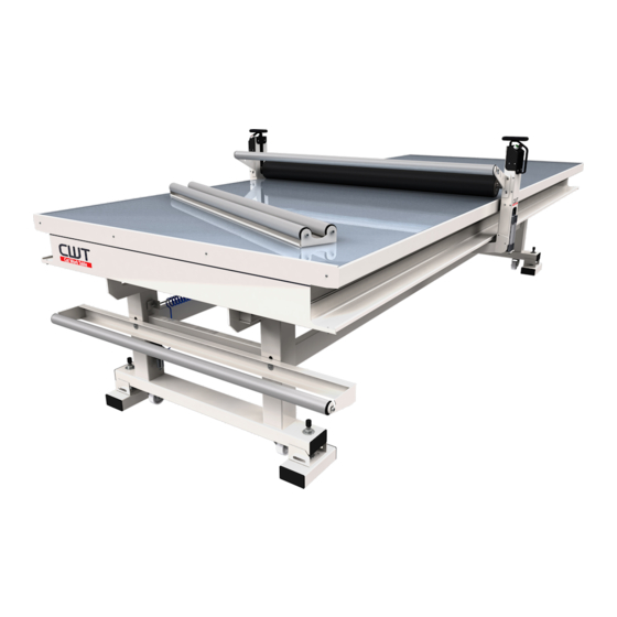
Assembly Guide
CWT Lamination Table
Preassembled Version
CWT 1630
CWT 1640
CWT 1647
CWT 1840
CWT 1847
CWT 2140
CWT 2147
Table of
Contents
Previous
Page
Next
Page
1
2
3
4
5
Advertisement
Need help?
Do you have a question about the 1630 and is the answer not in the manual?
Ask a question
Questions and answers
Related Manuals for CWT 1630
Laminator CWT Platinum 1736 Assembly Manual
Flatbed applicator (28 pages)
Laminator CWT 1640 Assembly Manual
Lamination table (26 pages)
Laminator CWT Advantage 1428 Assembly Manual
Lamination table (29 pages)
Laminator CWT 1428 Advantage Assembly Manual
Lamination table (29 pages)
Laminator CWT 2147 Assembly Manual
Lamination table (26 pages)
Laminator CWT EXPRESS Use And Maintenance Manual
Hot roller laminator (60 pages)
This manual is also suitable for:
1640
1647
1840
1847
2140
2147
Print
Rename the bookmark
Delete bookmark?
Delete from my manuals?
Login
Sign In
OR
Sign in with Facebook
Sign in with Google
Upload manual
Upload from disk
Upload from URL


Need help?
Do you have a question about the 1630 and is the answer not in the manual?
Questions and answers