
Related Manuals for Blue X IntraOs 70

Summary of Contents for Blue X IntraOs 70
- Page 1 IntraOs 70 X-ray Equipment Service & Installation Manual Blue X Imaging Srl Via Idiomi 1/8-33 20090 Assago ITALY e-mail bluex@bluex.it...
- Page 2 IntraOs 70 – Service & Installation M Service & Installation Manual Control panel and exposure pushbutton button Medical device for emission of ionizing radiation on request evice for emission of ionizing radiation on request System turned ON and ready Irradiation...
- Page 3 IntraOs 70 – Service & Installation Manual Layout Power Board Timer AutoSet Layout Power Board Timer AutoSet POWER SUPPLY 5 V LED SET-UP KEYBOARD MICROSWITCHES CONNECTOR BACK UP TIMER BACK UP TIMER TEST POINT & LED TEST POINT & LED...
- Page 4 IntraOs 70 – Service & Installation M Service & Installation Manual Blue X Imaging S.r.l. Via Mario Idiomi 1/8-33 20090 Assago ITALY tel.+39.0245712171 fax +39.0245703385 e-mail bluex@bluex.it www.bluex.it IntraOs 70 Dental X-ray Equipment Service & Installation Manual – English Edition English Edition Version 4.0 March 2008...
-
Page 5: Table Of Contents
IntraOs 70 – Service & Installation Manual Table of Contents INTRODUCTION ........................7 Purpose ........................7 Equipment Classification .................... 7 Applicable Standards ....................7 Environmental Data ...................... 7 Obligations of the Installer ..................8 Warning.............. - Page 6 IntraOs 70 – Service & Installation M Service & Installation Manual Appendix A System Components ....................46 Appendix B Icons ........................47 Appendix C Exposure Table ......................48 Appendix D Alarm Conditions ..................... 49 Appendix E Identification Labels ..............
-
Page 7: Introduction
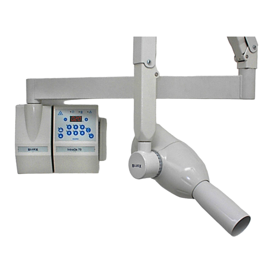
IntraOs 70 – Service & Installation Manual 1. INTRODUCTION Purpose The IntraOs 70 X-ray Equipment is design to fulfil the needs for intra ipment is design to fulfil the needs for intra-oral radiography in the general dental practice. The system can be configured for wall, unit or mobile solutions and different The system can be configured for wall, unit or mobile solutions and different types of timers and tube-heads. -
Page 8: Obligations Of The Installer
IntraOs 70 – Service & Installation M Service & Installation Manual Obligations of the Installer Obligations of the Installer are: To make sure that the line voltage specified by the Manufacturer of the equipment is available and within the Manufacturer of the equipment is available and within the specified range. -
Page 9: Technical Data
IntraOs 70 – Service & Installation Manual 2. TECHNICAL DATA System Supply Line Voltage 115 V (from 99 V to 137 V in sub V in sub-ranges depending on tube housing assembly) assembly) 230 V (from 198 V to 275 V in sub... -
Page 10: Beam Limiting Device
IntraOs 70 – Service & Installation M Service & Installation Manual Beam Limiting Device Metal cone with near-focus section focus section Round BLD Focus skin distance (FSD) 8.27”(21 cm) 8.27”(21 cm) Circular radiation field size 2.35” diameter (6 cm) Metal body with near-focus section... -
Page 11: Mechanical Suspension System
IntraOs 70 – Service & Installation Manual Mechanical Suspension System Mechanical Suspension System Wall Support 4.72” (12 cm) width, 9.45” (24cm) height, 3.54” (9 cm depth) Extension arm, length Short: 17”¾ (45 cm), medium:27”½ (70 cm), long 35”½ (90 cm), extra long 43”¼... -
Page 12: Assembly And Installation
IntraOs 70 – Service & Installation M Service & Installation Manual 3. ASSEMBLY AND INSTALLATION Wall Mounted Systems 3.1.1 Unpacking Unpack the components of the system and check the following: Each item is in good conditions and was not damaged during transportation. - Page 13 IntraOs 70 – Service & Installation Manual kg. Proper expansion screw to be selected for a solid connection to the onnection to the concrete wall; the permissible load of each screw has to be to be greater than 308 lbs (about 140 kg).
- Page 14 IntraOs 70 – Service & Installation M Service & Installation Manual The X-ray head is connected to the output terminals of the timer (OUT) y head is connected to the output terminals of the timer (OUT) through the connecting block in the wall support.
- Page 15 IntraOs 70 – Service & Installation Manual 3.1.5 Mounting the Wall Support Remove the plastic cover unscrewing the screws under the logo label. Use the Wall Support plate or a template to mark the holes on the wall. Please note that the timer...
- Page 16 IntraOs 70 – Service & Installation M Service & Installation Manual 3.1.6 Mounting the Timer Use the mounting plate or the template to mark the holes on the wall. Slide the logo-strip out from the plastic cover to access the screws and remove the plastic cover from the plastic frame.
- Page 17 IntraOs 70 – Service & Installation Manual 3.1.8 Mounting the Folding Arm WARNING. THE SPRINGS IN THE FOLDING ARM MAY CAUSE INJURY TO THE INSTALLER AS WELL AS DAMAGE TO THE ARM ITSELF IF NOT HANDLED PROPERLY. DO NOT REMOVE BINDING UNTIL WHEN NECESSARY AS INDICATED IN THE INSTRUCTIONS BELOW.
- Page 18 IntraOs 70 – Service & Installation M Service & Installation Manual 3.1.9 Connecting the Wall Support EXTENSION FROM FOLDING TIMER GROUND CONNECTIONS ON WALL PLATE WALL SUPPORT CONNECTIONS Connect the three wires from the Timer (additional cable) to the Connect the three wires from the Timer (additional cable) to the terminal...
- Page 19 IntraOs 70 – Service & Installation Manual 3.1.10 Connecting the Timer Turn-off the line voltage supply line. FUSE F4 FUSE F4 NEUTRAL GROUND LIVE ZERO OHM RESITOR HAND HAND-SWITCH CONNECTION CONNECTION FUSE F2 JUMPERS HAND-SWITCH SWITCH SOCKET TST2 SOCKET TST2...
- Page 20 IntraOs 70 – Service & Installation M Service & Installation Manual Connect the load. Turn OFF the line LIVE IN NEUTRAL OUT voltage supply line, LIVE OUT NEUTRAL IN GROUND Connect the three wires of additional FROM LINE cable outgoing to the...
- Page 21 IntraOs 70 – Service & Installation Manual 3.1.13 Mounting and Connecting the Tube-Head Remove retaining screws and cover plate on inner side of terminal pole retaining screws and cover plate on inner side of terminal pole (handgrip) of Folding/Simple Arm at tube-head side.
- Page 22 IntraOs 70 – Service & Installation M Service & Installation Manual 3.1.15 Final Tuning and Set-Up Remove the line voltage fuse(s) from the timer Put back the cover plate on the folding/simple arm (tube- -head side) Tighten locking screw and tune friction screw in Extension Arm.
- Page 23 IntraOs 70 – Service & Installation Manual DIP 1 DIP 2-3 DIP 5-6-7 DOSE COMPENSATION TUBE-HEAD TYPE PRE-HEATING TIMES DIP 4 DIP 8 NOT USED NOT USED USED • Enable/disable exposure time • Set pre-heating time as heating time as...
- Page 24 IntraOs 70 – Service & Installation M Service & Installation Manual 3.1.16 Layout Power Board Timer AutoSet POWER SUPPLY 5 V LED SET-UP KEYBOARD MICROSWITCHES CONNECTOR BACK UP TIMER BACK UP TIMER TEST POINT & LED TEST POINT & LED...
-
Page 25: Mobile Systems
IntraOs 70 – Service & Installation Manual Mobile Systems 3.2.1 Unpacking Unpack the components of the system and check the following: Each item is in good conditions and was not damaged during transportation. All the items for the desired system configuration are available. - Page 26 IntraOs 70 – Service & Installation M Service & Installation Manual 3.2.3 Mounting and Connecting Sequence The recommended sequence to mount and connect system modules is listed here below. Assembly the Mobile Stand. Mount the Timer. Mount the Suspension Arm.
- Page 27 IntraOs 70 – Service & Installation Manual 3.2.7 Connecting the Line voltage Cable The line voltage cable for the mobile unit is provided with plug. is provided with plug. The grounding wire of the main cable has to be blocked...
-
Page 28: Maintenance
Manufacturer, or its Agent, from responsibility for any injury, damage or non compliance which may result. The suggested frequency for checks of the IntraOs 70 system if of at least 70 system if of at least once every 12 months, with a specific maintenance of the folding arm every once every 12 months, with a specific maintenance of the folding arm every 24 months, performed by qualified personnel. -
Page 29: Maintenance Of The Wall Support
IntraOs 70 – Service & Installation Manual Maintenance of the Wall FRICTION Support SCREW Remove the cover and verify that the mounting is closely connected to the wall and stays firm and steady during various movements of the system. Verify that the ground cable of the wall support is properly connected to the wall plate and to the blocking bolt on the extension arm. -
Page 30: Maintenance Of The Folding Arm
IntraOs 70 – Service & Installation M Service & Installation Manual Maintenance of the Folding Arm Specifically for the folding arm inspect for wear of pins and levers inspect for wear of pins and levers at least every 24 months, in case of normal use (about 6000 cycles). Replace the e (about 6000 cycles). - Page 31 IntraOs 70 – Service & Installation Manual Fig. 1 Fig. 2 Fig. 3 Fig. 6 BENT ARM (IN SHADE) INDICATES WEARING OUT OF BASIC PIN Fig. 4 Fig. 5 Fig. 7 Fig. 8 Fig. 9 Version 4.0 69 500 00210...
- Page 32 IntraOs 70 – Service & Installation M Service & Installation Manual Fig. 10 Fig. 11 Fig. 12 Fig. 13 Fig. 14 Fig. 15 Fig. 16 Fig. 17 Fig. 18 32/52 69 500 00210 Version 4.0...
- Page 33 IntraOs 70 – Service & Installation Manual Be careful not to pinch fingers between the two sections of the arm ns of the arm while manoeuvring (fig. 4). In the second section of the arm remove the two snap-out caps...
-
Page 34: Maintenance Of The Tube-Head
IntraOs 70 – Service & Installation M Service & Installation Manual Maintenance of the Tube-Head Inspect for damage/wear to the X-ray tube-head and support system. head and support system. Inspect for oil leakage. Replace tube-head if necessary. Check for position stability. -
Page 35: Checking Filament Pre-Heating Time
IntraOs 70 – Service & Installation Manual for “Exposure push button pressed at power on”, d) alarm for alarm for “Exposure stopped by the operator”. Verify that the fuses mounted comply with what specified in the table Verify that the fuses mounted comply with what specified in the table below. -
Page 36: Measurements
IntraOs 70 – Service & Installation M Service & Installation Manual Test of Control Panel. This function is intended to test lights, buttons, Test of Control Panel. This function is intended to test lights, buttons, and segments of numerical display on the control panel. -
Page 37: Exposure Time
IntraOs 70 – Service & Installation Manual occur in case of improper operation The Anode current in mA is the actual average value of the tube current which raises when the filament has warmed- up, after the preheating time has elapsed. -
Page 38: Leakage Radiation
IntraOs 70 – Service & Installation M Service & Installation Manual When the actual line voltage is higher than the nominal line voltage, the tual line voltage is higher than the nominal line voltage, the actual exposure time is decreased. -
Page 39: Earth Leakage
IntraOs 70 – Service & Installation Manual Earth Leakage Connect the Timer to the measuring circuit as shown in the figure (R1=10 kΩ ± 5%, R2=1 kΩ ± 1%, C1=0,015 µF ±5%) Set the input supply voltage (Vp) equal to 110% of the nominal supply voltage. -
Page 40: Spare Parts
IntraOs 70 – Service & Installation M Service & Installation Manual 6. Spare Parts Tube-Head 93 200 01700: G 230 V without BLD 93 200 01300: G 120 V without BLD List of Spare Parts – Figure TH Item Description... -
Page 41: Folding Arm
IntraOs 70 – Service & Installation Manual Folding Arm 93 100 12010: for Wall Mount List of Spare Parts - Figure FA Item Description Code Tube head support for folding arm 76 190 25251 for SN lower than FA0501 0501 76 190 25250... -
Page 42: Extension Arm
IntraOs 70 – Service & Installation M Service & Installation Manual Extension Arm 93 100 17100 – 45 cm 93 100 17200 – 70 cm 93 100 17300 – 90 cm 93 100 17400 – 110 cm List of Spare Parts – Figure EA... -
Page 43: Wall Support
IntraOs 70 – Service & Installation Manual Wall Support 93 100 11000 List of Spare Parts - Figure WS Item Description Code 76 190 25190 Plastic Cover Wall Mount Logo Strip Blue X 76 190 25200 Figure WS Version 4.0... -
Page 44: Mobile Base
IntraOs 70 – Service & Installation M Service & Installation Manual Mobile Base 93 100 20080 93 100 20090 List of Spare Parts – Figure MB Item Description Code 76 190 25280 Transport Handle (set of 2) Cable Holder With Strain Relief... -
Page 45: Autoset Timer
IntraOs 70 – Service & Installation Manual AutoSet Timer 93 300 60100: 230 V 93 300 60200: 115 V List of Spare Parts – Figure AU Item Description Code Front Cover 76 190 25220 76 190 25230 Mounting Plate Mounting Columns... - Page 46 IntraOs 70 – Service & Installation M Service & Installation Manual Appendix A System Components Article Type Code System Component Catalogue Number Wall Support 93 100 11000 Extension Arm 45 cm 93 100 17100 Extension Arm 70 cm 93 100 17200...
- Page 47 IntraOs 70 – Service & Installation Manual Appendix B Icons IEC Type B Compliance to European Compliance to European Equipment Community Requireme Community Requirements Compliance to Canadian and Compliance to Canadian and X-ray On US Standards US Standards Examine Annexed...
- Page 48 IntraOs 70 – Service & Installation M Service & Installation Manual Appendix C Exposure Table IntraOs 70 - 70 kVp, 7 mA - Exposure Times in s Small Patient Large Patient 3,20 2,50 2,00 2,60 1,25 1,00 0,80 0,64 0,50 0,40...
- Page 49 IntraOs 70 – Service & Installation Manual Appendix D Alarm Conditions AutoSet Timer Alarm Conditions Code Fault /Error Signal Action Reset Reset X-ray requested Green lamp System acknowledgement acknowledgement A 01 during cool-down (System Ready) inhibited on the panel or when...
- Page 50 IntraOs 70 – Service & Installation M Service & Installation Manual Appendix E Identification Labels 50/52 69 500 00210 Version 4.0...
- Page 51 IntraOs 70 – Service & Installation Manual Appendix F Cooling Curves Version 4.0 69 500 00210 51/52...
- Page 52 IntraOs 70 Dental X-ray Equipment Service & Installation Manual English Edition Version 4.0 *6950000210*...
Need help?
Do you have a question about the IntraOs 70 and is the answer not in the manual?
Questions and answers