
Related Manuals for Blue X IntraOs 70

Summary of Contents for Blue X IntraOs 70
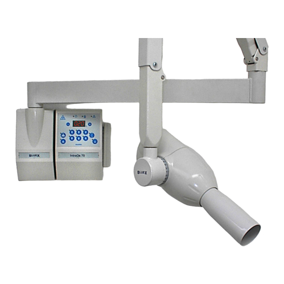
- Page 1 IntraOs 70 X-ray Equipment Operator’s Manual Blue X Imaging Srl Via Idiomi 1/8-33 20090 Assago ITALY e-mail bluex@bluex.it...
- Page 2 IntraOs 70 X-ray Equipment Operator’s Manual – English Edition USA Version 3.2 December2006 Printed 04/12/2006 11:20 AM Code 69 500 01110 Blue X Imaging is committed to Total Quality. Thank you for notifying us any error found in this document.
-
Page 3: Table Of Contents
IntraOs 70 – Operator’s Manual Table of Contents Introduction ...................4 Congratulations..............4 Purpose ..................4 Equipment Classification............4 Applicable Standards.............4 Obligation of the Installer............5 Obligation of the User ............5 Warning .................5 Technical Data................6 Tube-Head G .................6 Beam Limiting Device ............7 Mechanical System..............7 Weights..................8 AutoSet Timer ...............9... -
Page 4: Introduction
The unit is manufactured under a Quality Control System which grants full compliance to specifications. 1.2 Purpose The IntraOs 70 X-ray Equipment is design to fulfil the needs for intra- oral radiography in the general dental practice. The system can be configured for wall, unit or mobile solutions and different types of timers and tube-heads. -
Page 5: Obligation Of The Installer
IntraOs 70 – Operator’s Manual 1.5 Obligation of the Installer Obligation of the Installer is: • To make sure that the line voltage specified be the Manufacturer of the equipment is available and within the specified range. • For safety reasons verify that a proper switch is... -
Page 6: Technical Data
IntraOs 70 – Operator’s Manual Make sure to carefully manoeuvre the suspension arms to position the tube-head in order prevent harm to the fingers in areas where they may be pinched. Even if compliant to specifications of electromagnetic compatibility, it... -
Page 7: Beam Limiting Device
IntraOs 70 – Operator’s Manual 2.2 Beam Limiting Device • Circular Output Section • Rectangular Output Section Focus Skin Distance: Focus Skin Distance: 8.27”(21 cm) 8.27”(21 cm) Output Radiation Field: Output Radiation Field: 2.35” diameter (6 cm) 1.8”x 1.81” (3.5 x 4.6 cm) 2.3 Mechanical System... -
Page 8: Weights
IntraOs 70 – Operator’s Manual • Folding arm; useful reach of 55” (140 cm) with 17”¾ (45 cm) extension arm 65” (165 cm) with 27”½ (70 cm) extension arm 72”¾ (185 cm) with 35”½ (90 cm) extension arm 80” (205 cm) with 43”¼... -
Page 9: Autoset Timer
IntraOs 70 – Operator’s Manual 2.5 AutoSet Timer The timer is working at line voltage of 115 V ± 15%, 50/60 Hz. Mains features are: • Microprocessor controlled functionality • Zero-crossing power switching. • Film speed setting. • Automatic setting of exposure time from 60 ms to 3.2 s through object selection. -
Page 10: Operating Instructions
IntraOs 70 – Operator’s Manual 3. OPERATING INSTRUCTIONS 3.1 Demonstration In order to use of the system for demonstration purposes radiation emission has to be inhibited by disconnecting the supply cables to the tube-head into the wall support or into the timer. - Page 11 IntraOs 70 – Operator’s Manual Index 0.32 0.40 0.50 0.64 0.80 1.00 1.25 1.60 2.00 Speed E type D type D type: Kodak Ultraspeed, Agfa Dentus M2 - E type: Kodak Ektaspeed Plus The timer offers the possibility to correct the exposure time to compensate radiation dose changes due to fluctuations of the line voltage supply, thus granting consistent film blackening.
- Page 12 IntraOs 70 – Operator’s Manual To operate the systems switch the timer “on” with the button below the unit. During start-up all the lamps in the panel and the segments of the display, but the yellow light of X-ray On , are blinking for 3 s, to let the operator check that lights in the panel are properly working.
- Page 13 IntraOs 70 – Operator’s Manual During the exposure the yellow lamp of X-ray On , on the timer and on the hand-switch, lights and the internal buzzer sounds to indicate radiation emission. As additional safety feature the timer is provided of an independent back-up device (back-up timer and back-up relay) which is going to cut-off radiation in case of failure of the main timer.
-
Page 14: Operation
IntraOs 70 – Operator’s Manual 3.4 Operation Turn on the line voltage supply switch on (below the timer) to bring the system ready EXPOSURE HAND-SWITCH CONNECTION Position the image receptor LINE-SWITCH where needed and orientate the ON/OFF BLD accordingly. Select the desired exposure time (using the keys or the knob depending on the type of timer connected). -
Page 15: Safety
IntraOs 70 – Operator’s Manual 3.5 Safety • Electrical. Trained and qualified technicians only are authorized to remove covers and have access to power circuits. Power supply lines must comply with safety legislation and have ground terminals for protective earth connection. -
Page 16: Disinfecting
Refer to Service & Installation Manual for instructions. 4. DISPOSING OF OBSOLETE EQUIPMENT The IntraOs 70 system is made of different materials which include may kinds of metals, iron, aluminium, lead, copper and others, plastic materials, electronic components and dielectric oil in the tube-head. -
Page 17: Appendix A System Components
IntraOs 70 – Operator’s Manual Appendix A System Components Article Type Code System Component Catalogue Number Wall Support 93 100 11000 Extension Arm 45 cm 93 100 17100 Extension Arm 70 cm 93 100 17200 Extension Arm 90 cm 93 100 17300... -
Page 18: Appendix B Icons
IntraOs 70 – Operator’s Manual Appendix B Icons Compliance to IEC Type B European Community Equipment Requirements Compliance to Canadian and US X-ray On Standards Examine Annexed Line voltage supply Documentation On - System Ready Increase Exposure Off (Disconnected Time (one step) -
Page 19: Appendix C Exposure Table
IntraOs 70 – Operator’s Manual Appendix C Exposure Table IntraOs 70 - 70 kVp, 7 mA - Exposure Times in s Small Patient Large Patient 3,20 2,50 2,00 2,60 1,25 1,00 0,80 0,64 0,50 0,40 0,32 2,50 2,00 2,60 1,25 1,00 0,80 0,64 0,50 0,40 0,32 0,25... -
Page 20: Appendix D Alarm Conditions
IntraOs 70 – Operator’s Manual Appendix D Alarm Conditions AutoSet Timer Alarm Conditions Code Fault /Error Signal Action Reset A 01 X-ray requested Green lamp System By acknowledgement during cool-down (System Ready) inhibited on the panel or when period flashing... -
Page 21: Appendix E Identification Labels
IntraOs 70 – Operator’s Manual Appendix E Identification Labels... -
Page 22: Appendix F Cooling Curves
IntraOs 70 – Operator’s Manual Appendix F Cooling Curves COOLING CURVE OF X-RAY TUBE T (min) COOLING CURVE OF TUBE-HEAD T (min) - Page 23 Page intentionally left blank...
- Page 24 IntraOs 70 Dental X-ray Equipment Operator’s Manual English Edition USA Version 3.2...
Need help?
Do you have a question about the IntraOs 70 and is the answer not in the manual?
Questions and answers