
Related Manuals for Bogen UTI1


Summary of Contents for Bogen UTI1
- Page 1 Universal Telephone Interface UTI1 Model Installation and Use Manual © 2004 Bogen Communications, Inc. All rights reserved. Specifications subject to change without notice. 54-2095-01A 0406...
- Page 2 - Relocate the UTI1 unit with respect to the radio or TV receiver or vice versa. - Plug the UTI1 unit into a different outlet so that it and the radio or TV receiver are on different branch circuits. If necessary, the user should consult the dealer or an experienced radio/television technician for additional suggestions.The user may find...
-
Page 3: Table Of Contents
Contents UTI1 Feature Callouts ...4 Introduction ...5 Voice Channel ...5 Background Music ...5 Signaling Tones ...5 Other Features ...5 Package Contents ...5 Installation ...6 Wall Mounting ...6 Telephone Interface Wiring Connections & Setup ...7-10 Telephone System Connections...7 Trunk Disconnect ...7 PBX Loop Start Trunk Port ...7... -
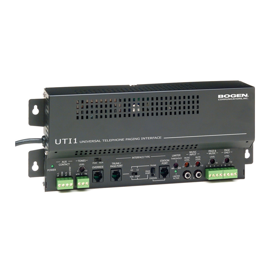
Page 4: Uti1 Feature Callouts
5. Override - Secondary paging input with higher priority than TRUNK/PAGE PORT or STATION mode inputs. Connects to either loop start trunk or dry audio signal with contact closure. 6. Trunk/Page Port - Primary paging interface to telephone system when UTI1 is set to trunk or page port mode type interface. -
Page 5: Introduction
Introduction The UTI1 Paging System is a paging and signaling system.The system provides the following features and functions: Voice Channel • Single-zone paging • Telephone interfaces: - loop start trunk - ground start trunk - station access (analog ring-up) - page port contact closure activation - page port voice activation •... -
Page 6: Installation
Installation Wall Mounting Mounting to a plywood backboard or studs: 1. Hold the unit level against the surface to which it will be mounted. Mark where the mounting screws should be positioned. Set the unit aside and install the screws leaving about Slip the unit over the screws and tighten them snugly. -
Page 7: Telephone Interface Wiring Connections & Setup
The UTI1 includes a trunk disconnect feature.The purpose of the trunk disconnect feature is to release the UTI1 from the trunk port in the event a user does not hang up the phone properly after making a page. If the UTI1 does not detect voice for the interface VOX time-out period, or if the interface default timer expires, the UTI1 will attempt to release from the trunk. -
Page 8: Pbx Ground Start Trunk Port
If the UTI1 system ground is tied to earth ground, then the UTI1 talk battery voltage will be shorted to ground and the unit will not function properly. -
Page 9: Pbx Page Port Vox
Make sure that the power is off and all connections are completed before proceeding. Move the interface slide switch on the UTI1 to STATION. The other interface slide switch is not used and can be in any position. Use a modular telephone cord (minimum 2-conductor) to connect the UTI1 Station Port RJ11 to the phone system.The... -
Page 10: Override Input
The center two conductors interface directly to a Loop Start Trunk or a dedicated phone.When the trunk becomes active, the UTI1 goes into Override mode.A contact closure and dry audio source can also be used for the Override Input. The two conductors flanking the talk battery conductors provide a dry audio gateway into the system override. -
Page 11: Other Connections
Mono sources can be connected to either RCA. AUX Contacts The UTI1 system provides a dual form contact rated at 2A @ 30V DC and 0.6A @ 125V AC, which can be used to activate external equipment.The relay can be programmed to change state when specific events or combination of events (time tone, override, night ring, paging) occur. -
Page 12: Controls
Controls Paging Level The UTI1 has controls for adjusting the audio level of each output independently. These serve as master level controls that allow for overall system control. Setting the initial volume to half is a good starting point. If the speakers have their own level control, then the installer will have to determine the proper setting for each speaker depending on the application. -
Page 13: Tones
2 - 7 Second Tone Burst - This is a tone burst that, once a momentary closure is detected at the tone trigger input, will sound for the set duration one time.The UTI1 will not respond to the tone trigger input while the tone is in progress. -
Page 14: System Programming
DTMF Block can be enabled or disabled (Feature Codes 40 and 41). If enabled, DTMF Block suppresses DTMF tones issued to the UTI1 so that only a small portion of the tone will be heard over the paging system. If external DTMF controlled devices are connected to the output T/R terminals of the UTI1, the DTMF Block feature will have to be disabled in order for these devices to receive DTMF tones. -
Page 15: Aux Relay Contact
UTI1 detects that as a particular event.Through programming, the installer can decide which of these 4 events the UTI1 will allow to activate the AUX relay. Setting the event to Enable allows the AUX contact to respond to that event. - Page 16 UTI1 will consider that the AUX relay event has finished even if it hasn't, and the relay will change states. If the Delay option is selected, then the UTI1 will pulse the AUX relay contacts.
-
Page 17: Feature Codes And Defaults
Feature Codes & Defaults Feature Handset & Outputs Destination Pre-Announce / Confirmation Tone Tone Override Tone Trunk Disconnect Slow Whoop Follow Contact Tone Follow Contact Tone Trigger Double Chime Follow Night Ring DTMF Block Timers Override Disabled Override Enabled Tone Trigger Disabled Tone Trigger Enabled Aux Relay Response... -
Page 18: Specifications
Specifications Music Source Input Impedance: Music Input Level: Output Impedance: Dimensions/Weight: Input Impedance: 600 ohms Input Level: -10 dBm nominal VOX Sensitivity: -30 dBm 8 to 600 ohms -10 dBm 8 ohms Output Level: -10 dBm nominal Contact Closure: 2A @ 30V DC 0.6A @ 125V AC DC Output: 1A @ 24V DC... -
Page 19: Block Diagram
Block Diagram... -
Page 20: Limited Warranty
Limited Warranty The UTI1 is warranted to be free from defects in material or workmanship for two (2) years from the date of sale to the original purchaser. Any part of the product covered by this warranty that, with normal installation and use, becomes defective will be repaired or replaced by Bogen, at our option, provided the product is shipped insured and prepaid to: Bogen Factory Service Department, 50 Spring Street, Ramsey, NJ 07446, USA.
Need help?
Do you have a question about the UTI1 and is the answer not in the manual?
Questions and answers