Table of Contents
Advertisement
CAPACITY
• (4) 18 in x 13 in / 460 mm x 330 mm half size pan
STANDARD EQUIPMENT
• (2) 4-level shelf holders, 2.92 in (74 mm) spacing
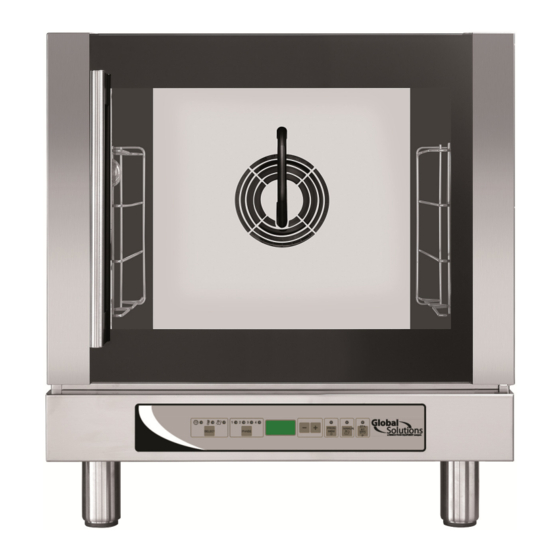
GS1125
FUNCTIONAL FEATURES
• Temperature range from 200° F to 500° F
• Cooking timer up to 9 hours and 59 minutes or run
on infinite for continuous heat
• 2 cooking options available:
- convection cooking
- convection cooking with humidty
• Humidity available in manual or automatic mode
(from 10% to 100%)
• 4 cooking phases available
• Available cooking cycle delay up to 9 hours and 59
minutes
• Maintain food temperature and quality by combining
heat and humidity
• Automatic pre-heating for programmed cooking
cycles
CONSTRUCTION FEATURES
• Stainless steel constructed cooking chamber and
shell
• Glass door to facilitate cooking and cleaning
operations
• Reversing fan motor to guarantee cooking
uniformity
• Recessed gasket to guarantee a sealed cooking
chamber
Advertisement
Table of Contents

Related Manuals for Global Solutions GS1125


Summary of Contents for Global Solutions GS1125
- Page 1 GS1125 FUNCTIONAL FEATURES CAPACITY • Temperature range from 200° F to 500° F • (4) 18 in x 13 in / 460 mm x 330 mm half size pan • Cooking timer up to 9 hours and 59 minutes or run on infinite for continuous heat •...
- Page 2 GS1125 – Digital Oven INSTALLATION REQUIREMENTS SIZE SPECIFICATIONS Weight without packaging: 95.7 lbs (43.4 kg) • The oven must be positioned on a level Height without packaging: 25.82 in (656 mm) surface Width without packaging: 23.62 in (600 mm) • Hot surfaces must comply with the minimum Depth without packaging: 27.83 in (707 mm)
- Page 3 GS1125 – Overall Dimensions Front View Side View Rear View Top View Door Open Water Inlet Steam Exhaust Pipe Power Cord Strain Relief...
-
Page 4: Table Of Contents
CONTENTS INTRODUCTION Page. 5 Identifying the danger or warning signals Purpose of the product INSTALLATION Page. 5 Installation requirements Transport Unpacking Installing the feet Placement Electrical connection Water connection Water drain Conditioning the appliance OPERATION INSTRUCTIONS Page. 9 Controls General cooking information CLEANING AND MAINTENANCE Page. -
Page 5: Identifying The Danger Or Warning Signals
INTRODUCTION Carefully read this user manual before using your new oven; pay special attention to the information highlighted with the WARNING, CAUTION, and NOTES symbols Identifying the danger or warning signals: WARNING This signal indicates the presence of danger, which may cause serious injury, death, or damage if disregarded. -
Page 6: Installing The Feet
Carefully remove the plastic film that protects stainless steel components. • Remove any glue residue, which may result from removing the protective film, using a non- flammable solvent. Installation of the feet WARNING Risk of fire. This appliance has been designed to operate with specific feet. Do not use the appliance without installing the feet first. -
Page 7: Water Connection
If the power cord is damaged, it must be replaced by the manufacturer or a qualified • service technician. If the oven is placed on a wheeled table, the connection conduit must be flexible. The • table wheels must be locked. Appliances supplied with power cord already fitted: Make sure that a suitable power cord and plug have been connected to the oven. -
Page 8: Conditioning The Appliance
NOTE Any damage caused by limescale or other chemicals contained in the water ARE NOT covered by warranty. NOTE The equipment must be installed with adequate backflow protection to comply with applicable federal, state, and local codes. Conditioning the Appliance Before the ovens first use it is recommended to run it with an empty cooking chamber for 60 minutes •... -
Page 9: Operation Instructions
OPERATION INSTRUCTIONS CONTROL PANELS The keys on the control panel should only be activated with your fingers, any other object or tool may cause damage and/or malfunctioning, hence forfeiting the product's warranty. 1) LED Signalling Active Parameter 6) Button to Decrease Parameter Value 2) Button to Select Cooking Parameters 7) Button to Increase Parameter Value 3) LED Signalling Active Phase 8) Button to Select/Store Cooking Program... - Page 10 • Press key to increase the parameter value, • Press key to decrease the parameter value. • The time parameter ( ) may be set from 0 hours and 01 minute to 9 hours and 59 minutes. If the display reads “INF” or “HLD” this means time counting is excluded, the oven runs nonstop until key is manually deactivated.
- Page 11 Press the key until all the signaling LEDs on the control panel go out and the display reads • “0.00” Press key and set the desired “DELAY TIME” on the display (maximum 9 hours and 59 • minutes) Press the key to begin the delayed start cycle.
-
Page 12: General Cooking Information
humidity/steam production continues for as long as the key is pressed. If an automatic humidification cycle is in progress, pressing the key will interrupt the cycle, but when the key is released the automatic humidification cycle resumes. GENERAL INFORMATION ON COOKING "Convection"... -
Page 13: Outer Stainless Steel Surfaces
Complete Cleaning Instructions Outer stainless steel surfaces The outer steel surfaces must be cleaned with a cloth soaked in warm soapy water or mixed with a small amount of vinegar. Once cleaned completely the surfaces must be rinsed using a cloth soaked in only warm water and then dried with a dry soft cloth. -
Page 14: Air Cover
Air cover 1) Remove the side supports from the cooking chamber, following the “Side Supports“ instructions provided. 2) Remove the (4) screws that fasten the air cover to the cooking chamber. 3) Remove the air cover from inside the oven and clean it with a mild detergent and hot water, using a soft bristle brush. - Page 15 For ovens with round light bulb covers 1) Remove the side supports from the cooking chamber, following the instructions below. 2) Unscrew (turn counter clockwise) the glass protection cap. 3) Remove the protection cap from the cooking chamber and remove the relative seal gasket (A). 4) Use a dry cloth to remove the light bulb from its socket and replace it with an exact match.
-
Page 16: Door Gasket
Door gasket - cleaning 1) Remove the gasket by pulling a a small section until it is free from the guide. Continue pulling to fully remove the gasket. Please remember that the door gasket has a rigid profile with retainer fins (B). This profile must be pressed into the guide on the front of the cooking chamber. - Page 17 External door glass cleaning Before cleaning the outer door glass, let the door cool down completely. Clean the glass with an approved detergent and a soft cloth. Internal door glass cleaning Before cleaning the inner door glass, let the door cool down completely. 1) With the oven door closed, loosen the upper, middle, and lower screws on the door profiles as shown.
-
Page 18: Troubleshooting
TROUBLESHOOTING Type of fault Cause of the fault Corrective action Incorrect connection to the power mains. Check connection to the mains Control panel blank – No lights Voltage not present in the mains. Restore power supply voltage displayed on Temperature high-limit tripped Reset the high-limit device control board Control board fuse (control panel) blown. - Page 19 GS1125 – Wiring Diagram Power terminal board Control Board High-Limit Switch Fuse Door Microswitch Contactor Oven Light Bulb Capacitors Fan Motor Solenoid-Valve for Humidifier Circular Heating-Element...
- Page 20 GS1125 - EXPLODED DRAWINGS 10321 10349 10327 10328 10306 10330 10269 10294 10274 10348 10331 10327 1032 10314 10232 10268 10318 10323 10262 10309 10254 10358 10246 10264...
- Page 21 GS1125 - EXPLODED DRAWINGS 10235 10276 10345 10284 102900 10237 10266 10317 10249 10313 10317 10229 10256 10313 10329 10257 10342 10231 10357 10342 10298 10236 10275 10293 10361 10265 10305 10273 10260 10225 10344 10295 10305 10233 10342 10357...
- Page 22 GS1125 – PARTS LIST SERVICE PART DESCRIPTION PART # 10249 30-BLADE FAN 160X40 MM 10225 PROBE PT100 FOR DIGITAL THERMOSTAT 10254 GLASS DOOR GLASS SPACER BUFFER 10256 PLASTIC INTERMEDIATE FITTING 10 - 8 10258 POLYETHYLENE PIPE LDPE 8X6 10265 ELBOW FITTING WITH TANG 8...
-
Page 23: Product Warranty
PRODUCT SERVICE Nemco has a staffed service department, and we believe prompt service is extremely important to our customers. Therefore, we request all product service inquiries be handled in the following manner: 1. The end user should call Nemco Customer Service with the company name, address, phone number, model number, serial number (if applicable), Nemco Sales Order number or Dealer Purchase Order number and the nature of the problem (the "Claim Information").
Need help?
Do you have a question about the GS1125 and is the answer not in the manual?
Questions and answers