Table of Contents
Advertisement
Quick Links
Advertisement
Table of Contents

Subscribe to Our Youtube Channel
Related Manuals for PG Drives Technology SIGMADRIVE Series


Summary of Contents for PG Drives Technology SIGMADRIVE Series
- Page 1 SIGMADRIVE AC TRACTION TECHNICAL MANUAL SK79646-01...
- Page 2 All rights reserved. This manual is furnished under copyright and may only be used in accordance with the terms laid out by PG Drives Technology. The information in this manual is furnished for informational use only, is subject to change without notice, and should not be construed as a commitment by PG Drives Technology.
-
Page 3: Table Of Contents
PG D – AC T RIVES ECHNOLOGY IGMADRIVE ECHNICAL ANUAL RACTION TABLE OF CONTENTS About this manual............. 6 Pin 6 – Speed Limit 2 / Inch Reverse ........ 20 Pin 7 – Speed Limit 3 / Handbrake........20 Icons ..............6 Pin 8 –... - Page 4 – AC T PG D IGMADRIVE ECHNICAL ANUAL RACTION RIVES ECHNOLOGY Speed Limit 2 / Inching Time Chapter 4 – Controller Set-Up ........45 – (Speed 2/InchTime)..........29 Controller Set-up..........47 Speed Limit 3 – (Speed 3)........29 Accelerator Characteristic – (Lin/Curv) ....48 Direction Regen.
- Page 5 PG D – AC T RIVES ECHNOLOGY IGMADRIVE ECHNICAL ANUAL RACTION 1.21 Braking Voltage Maximum – (B Vmax) ....60 CAN Node Set-up ..........78 1.22 Direction Braking Slip Minimum – (BDSmin) .... 60 Using the Programmer .........78 1.23 Direction Braking Slip Boost – (BDSboost)....60 Programmer Map ........79 1.24 Braking Slip Base (Rated) –...
-
Page 6: About This Manual
Caution – A point of safety which if ignored could result in damage to the control system or the vehicle. Warning – A point of safety which if ignored could cause injury to the individual. PG Drives Technology accepts no liability for any losses of any kind if these points are not followed. SK79646-01... -
Page 7: Chapter 1 - Installation
PG D AC T – I RIVES ECHNOLOGY RACTION NSTALLATION CHAPTER 1 – INSTALLATION SK79646-01... - Page 8 AC T – I PG D RACTION NSTALLATION RIVES ECHNOLOGY SK79646-01...
-
Page 9: Introduction
PG D AC T – I RIVES ECHNOLOGY RACTION NSTALLATION Introduction The Sigmadrive is an advanced digital controller for all popular motor types and is designed for electric vehicle applications such as Industrial Trucks, Personnel Carriers, Golf Cars, Aerial Work Platforms and Materials Handling Equipment. Advanced drive algorithms are employed to ensure smooth, accurate, predictable and efficient control of vehicle speed and torque. -
Page 10: Frame Dimensions
AC T – I PG D RACTION NSTALLATION RIVES ECHNOLOGY Although the controller is designed to be extremely reliable and each unit is rigorously tested during manufacture, the possibility of system malfunction always exists (however small the probability). Under some conditions of system malfunction the controller must (for safety reasons), stop the vehicle instantaneously. -
Page 11: Small Frame
PG D AC T – I RIVES ECHNOLOGY RACTION NSTALLATION Small Frame SK79646-01... -
Page 12: Medium Frame
AC T – I PG D RACTION NSTALLATION RIVES ECHNOLOGY Medium Frame SK79646-01... -
Page 13: Large Frame
PG D AC T – I RIVES ECHNOLOGY RACTION NSTALLATION Large Frame SK79646-01... -
Page 14: Mounting
AC T – I PG D RACTION NSTALLATION RIVES ECHNOLOGY Mounting Careful consideration should be given to the location chosen to mount the controller. Although the Sigmadrive benefits from excellent environmental protection, it is good engineering practice for the selected position to be clean and dry, to minimize shock, vibration, temperature changes and exposure to water &... -
Page 15: Wiring Guidance
PG D AC T – I RIVES ECHNOLOGY RACTION NSTALLATION Wiring Guidance SK79646-01... -
Page 16: Battery And Motor Connections
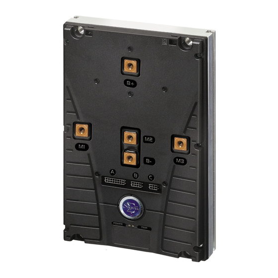
AC T – I PG D RACTION NSTALLATION RIVES ECHNOLOGY Battery and Motor Connections Five copper terminals with threaded holes are provided for the high current connections. These are identified as B+, B-, M1, M2 and M3. The controller is provided with suitable screws, spring washers and flat washers for fastening the battery and motor cables. -
Page 17: Battery And Motor Wire Size And Type Selection
PG D AC T – I RIVES ECHNOLOGY RACTION NSTALLATION Battery and Motor Wire Size and Type Selection The wiring arrangement used on a particular vehicle can greatly affect the current carrying capacities of individual wires. Ambient temperature, grouping and wire length can all significantly de-rate cable performance and other factors such as vehicle duty cycles and airflow should also be taken into consideration when selecting vehicle wiring. -
Page 18: Control Connections Crimps And Tooling
AC T – I PG D RACTION NSTALLATION RIVES ECHNOLOGY Control Connections Crimps and Tooling The following table shows the Molex part numbers for the mating crimps, housings, crimp tool and extraction tool. Alternatively, the mating connectors can be purchased directly from PGDT using the connector kit part numbers shown. Connector PGDT Connector Molex Housing... -
Page 19: Motor Connections
PG D AC T – I RIVES ECHNOLOGY RACTION NSTALLATION Motor Connections The three motor connections are marked M1, M2 and M3. There is no convention as to how these relate to the phase windings on individual motors, so the controller to motor connections are arbitrary. If, when a forward command is applied, the vehicle drives in reverse, swap any two of the motor connections. -
Page 20: Pin 6 - Speed Limit 2 / Inch Reverse
AC T – I PG D RACTION NSTALLATION RIVES ECHNOLOGY If set to Inch, then this input is used to “inch” the vehicle in the forward direction. Inching will occur when the switch is closed. The exact functionality of inching is set by the programmable parameters, 1.6 Inching Speed and 1.7 Inching Time. -
Page 21: Pin 10 - Keyswitch
PG D AC T – I RIVES ECHNOLOGY RACTION NSTALLATION When set to 0, the active range of the footbrake input is defined by the programmable parameters, 1.23 Footbrake 0% Voltage and 1.24 Footbrake 100% Voltage. The former parameter sets the voltage that relates to zero braking demand from the Footbrake, while the latter parameter sets the voltage that relates to 100% braking demand from the Footbrake. -
Page 22: Pin 11 - Contactor Coil Supply
AC T – I PG D RACTION NSTALLATION RIVES ECHNOLOGY Pin 11 – Contactor Coil Supply This output is the positive supply to the vehicle’s contactors. The voltage level of this supply corresponds to the vehicle’s battery voltage. The maximum supply current from this pin is 3A. Pin 12 –... -
Page 23: Pin 6 - Can H
PG D AC T – I RIVES ECHNOLOGY RACTION NSTALLATION Pin 6 – CAN H CAN High communications line to the Programming Device, Display or other Controller(s). Pin 7 – +12V Supply A 12V supply. The maximum supply current is 20mA from this pin. Pin 8 –... -
Page 24: Pin 5 - +12V Supply
AC T – I PG D RACTION NSTALLATION RIVES ECHNOLOGY The active range of the input when used by a steering potentiometer is defined by the parameters, 1.25 Steer Pot. Min., 1.26 Steer Pot. Mid. and 1.27 Steer Pot. Max. 1.25 Steer Pot. Min. sets the voltage that relates to the minimum (full left hand lock) steering angle, while 1.27 Steer Pot. -
Page 25: Chapter 2 - Adjustments
PG D AC T – A RIVES ECHNOLOGY RACTION DJUSTMENTS CHAPTER 2 – ADJUSTMENTS SK79646-01... - Page 26 AC T – A PG D RACTION DJUSTMENTS RIVES ECHNOLOGY SK79646-01...
-
Page 27: Adjustments
PG D AC T – A RIVES ECHNOLOGY RACTION DJUSTMENTS Adjustments The Sigmadrive Programmer ‘Adjustments’ menu (1. Adjustments), contains the parameters shown in the table below. Each parameter has a unique reference number, 1.x, as shown in the left-hand column. The parameter name as it appears on the Programmer screen and parameter range are also shown. -
Page 28: Acceleration - (Accel)
AC T – A PG D RACTION DJUSTMENTS RIVES ECHNOLOGY Acceleration – (Accel) This sets the time taken to accelerate from zero torque demand to maximum torque demand in Torque Control mode, or zero speed to maximum speed in Speed Control mode. The maximum torque demand is set from the motor set-up table. -
Page 29: Speed Limit 2 / Inching Time - (Speed 2/Inchtime)
PG D AC T – A RIVES ECHNOLOGY RACTION DJUSTMENTS The adjustable range is between 0Hz and 255Hz in 1.0Hz steps. The programmed value relates to the frequency output of the controller, i.e. the motor’s stator speed. If set to 1, then Inching Speed sets the speed of the vehicle (in both directions), that will be active when a switch connected to pin 5 or pin 6 of Connector A is closed. -
Page 30: Footbrake Regen. Braking - (Fbrake)
AC T – A PG D RACTION DJUSTMENTS RIVES ECHNOLOGY 1.11 Footbrake Regen. Braking – (FBrake) This sets the strength of the braking when the brake pedal is fully operated, i.e. the voltage from the footbrake potentiometer is equal to the setting of the parameter, 1.24 Footbrake 100% Voltage. The setting is a percentage of the maximum permissible braking slip, as set by the Braking Slip parameters, 4.24 &... -
Page 31: Neutral Braking End Delay - (Nbrkend)
PG D AC T – A RIVES ECHNOLOGY RACTION DJUSTMENTS 1.15 Neutral Braking End Delay – (NBrkEnd) This setting is normally associated with a Walkie type vehicle fitted with an electromechanical brake connected to pin 13 on Connector A. This setting allows a time to hold the vehicle at zero speed, i.e. hill hold, when the Neutral Braking Ramp time, 1.13 or Footbrake Ramp time, 1.14, have passed. -
Page 32: Footbrake 0% Voltage - (Auxmin)
AC T – A PG D RACTION DJUSTMENTS RIVES ECHNOLOGY The Accelerator input can be configured via the parameter, 3.14 Analogue Inputs Set-up, in the Controller Set-up menu. *If 3.14 Analogue Inputs Set-up in the Controller Set-up menu is set to ‘2’, the active range of the Throttle input is defined by the programmable parameters, 1.21 Accelerator 0% Voltage and 1.22 Accelerator 100% Voltage. -
Page 33: Reverse Threshold - (Revth)
PG D AC T – A RIVES ECHNOLOGY RACTION DJUSTMENTS Together with 1.29 Reverse Threshold, this parameter forms a ‘deadband’ in which the wig-wag assumes a neutral position. The adjustable range is 0V to 5V in 0.1V steps. 1.29 Reverse Threshold – (RevTH) The operation of this parameter is dependant on the setting of 3.14 Analogue Inputs Set-up, in the Controller Set-up Menu. -
Page 34: Dual Motor Cutback - (Dmcut)
AC T – A PG D RACTION DJUSTMENTS RIVES ECHNOLOGY 1.36 Dual Motor Cutback – (DMcut) 1.37 Dual Motor Angle 1 – (DMang1) 1.38 Dual Motor Angle 2 – (DMang2) 1.39 Dual Motor Angle 3 – (Dmang3) 1.40 Dual Motor Speed 1 – (DMspd1) 1.41 Dual Motor Speed 2 –... -
Page 35: Standby Delay - (Stdbydly)
PG D AC T – A RIVES ECHNOLOGY RACTION DJUSTMENTS The torque of the inner motor is halved to prevent a sudden increase in speed when steering rapidly beyond the 1.38 Dual Motor Angle 2 setting. The following graph shows an example of how these settings work with each other. 1.43 Standby Delay –... - Page 36 AC T – A PG D RACTION DJUSTMENTS RIVES ECHNOLOGY SK79646-01...
-
Page 37: Chapter 3 - Diagnostics
PG D AC T – D RIVES ECHNOLOGY RACTION IAGNOSTICS CHAPTER 3 – DIAGNOSTICS SK79646-01... - Page 38 AC T – D PG D RACTION IAGNOSTICS RIVES ECHNOLOGY SK79646-01...
-
Page 39: Error Detection
PG D AC T – D RIVES ECHNOLOGY RACTION IAGNOSTICS Error Detection If the controller detects an error, it can be displayed in up to four different ways. Firstly, the red LED on the controller itself will flash. The number of flashes in the sequence will reflect the error code. The error code can also be read by the Programmer. -
Page 40: Error Codes
AC T – D PG D RACTION IAGNOSTICS RIVES ECHNOLOGY Error Codes Once the error type has been noted, refer to the following table to identify the cause. If the error persists after taking the suggested action, contact your Service Agent. Code / LED Sigmagauge Cause / Action... - Page 41 PG D AC T – D RIVES ECHNOLOGY RACTION IAGNOSTICS Low-side MOSFET error in neutral. Check motor insulation and line contactor. If error persists, contact Service Agent. Controller error or line contactor coil error. Check line contactor coil. If error persists, contact Service Agent.
-
Page 42: Status
AC T – D PG D RACTION IAGNOSTICS RIVES ECHNOLOGY Status The Programmer’s Status menu shows a live-readout of parameter values. This is extremely useful when fine-tuning the system or carrying out diagnostic work. The table below gives details of the parameters that may be viewed. Some of the menu items have additional functions that can be accessed via the buttons. -
Page 43: Further Status Information
PG D AC T – D RIVES ECHNOLOGY RACTION IAGNOSTICS Further Status Information The status information, 2.10 Accelerator Slip Demand, also relays some operational status data about the controller. This is in the form of a two-letter abbreviation that replaces the “Hz” on the Programmer’s screen. These abbreviations are listed below. Neutral, i.e. -
Page 44: Test
AC T – D PG D RACTION IAGNOSTICS RIVES ECHNOLOGY Test The Programmer’s Test menu allows a live-readout of the controller’s inputs and outputs. This is extremely useful when carrying out diagnostic work. The table below gives details of the inputs and outputs that may be viewed. Ref. -
Page 45: Chapter 4 - Controller Set-Up
PG D AC T – C RIVES ECHNOLOGY RACTION ONTROLLER CHAPTER 4 – CONTROLLER SET-UP SK79646-01... - Page 46 AC T – C PG D RACTION ONTROLLER RIVES ECHNOLOGY SK79646-01...
-
Page 47: Controller Set-Up
PG D AC T – C RIVES ECHNOLOGY RACTION ONTROLLER Controller Set-up The Sigmadrive Programmer ‘Controller Set-up’ menu (3. Controller Set-up), contains the parameters shown in the table below. Each parameter has a unique reference number, 3.x, as shown in the left-hand column. The right-hand column shows the parameter name as it appears on the Programmer screen. -
Page 48: Accelerator Characteristic - (Lin/Curv)
AC T – C PG D RACTION ONTROLLER RIVES ECHNOLOGY Accelerator Characteristic – (Lin/Curv) This sets the type of response for the Accelerator Input (pins 8 or 9 on Connector A). There are two options for AC Traction control, Linear and Curved. The definition of each type is detailed below. -
Page 49: Anti Roll-Off (Hill Hold & Restraint) - (Off/Arol)
PG D AC T – C RIVES ECHNOLOGY RACTION ONTROLLER Anti Roll-off (Hill Hold & Restraint) – (Off/Arol) This sets whether there is a hill-hold and/or restraint function when the vehicle is at rest. There are three programmable options – 0, 1 and 2. If set to 0 (Coast), then there is no restraint function and the vehicle is free to coast. -
Page 50: Truck Type Select (Ride/Wlk)
AC T – C PG D RACTION ONTROLLER RIVES ECHNOLOGY If set to 3 (Footswitch & Motor Speed), then the power steer contactor is driven on the Footswitch as described above but also when the motor speed is greater than zero. This can be useful in combination with 3.4 Anti Roll-off. Truck Type Select (Ride/Wlk) This sets the function of the input pins 3 and 4 on Connector A. -
Page 51: Not Used
PG D AC T – C RIVES ECHNOLOGY RACTION ONTROLLER If set to 5 (Motor Current), then the motor current in units of ‘A’ will be displayed, from 0 to the maximum rated current of the controller. 1.12 Not Used Not used. -
Page 52: Can Node Number - (Can Node)
AC T – C PG D RACTION ONTROLLER RIVES ECHNOLOGY 1.17 CAN Node Number – (CAN node) The sets the CAN node number for the controller. There are sixteen programmable options – 0 to 15. If set to 0 (Master), then this controller is responsible for the following: General Indication Field as described in 3.11 Display Status Field. -
Page 53: Chapter 5 - Motor Set-Up
PG D AC T – M RIVES ECHNOLOGY RACTION OTOR CHAPTER 5 – MOTOR SET-UP SK79646-01... - Page 54 AC T – M PG D RACTION OTOR RIVES ECHNOLOGY SK79646-01...
-
Page 55: Motor Set-Up
PG D AC T – M RIVES ECHNOLOGY RACTION OTOR Motor Set-up Alteration of these parameters is only permitted when the vehicle is not pulsing. Ref. Parameter Programmer Text Motor Temperature Cutback TempStrt Motor to Vehicle Speed Ratio SpdRatio Number of Teeth SpdTeeth Number of Motor Poles SpdPoles... -
Page 56: Motor Temperature Cutback - (Tempstrt)
AC T – M PG D RACTION OTOR RIVES ECHNOLOGY Motor Temperature Cutback – (TempStrt) This sets the point at which the controller will begin to reduce its current output, in order to protect the motor. The temperature is measured by the motor’s thermal sensor, which provides feedback via pin 4 of Connector C. The output will reduce linearly to zero at a point set by the value of this parameter plus 10ºC. -
Page 57: Motor Driving Set-Up Explained
PG D AC T – M RIVES ECHNOLOGY RACTION OTOR :: Motor Driving Set-up Explained :: The graph below shows the twelve parameters that are involved in setting up the drive performance of the controller & motor combination. Each of these parameters is explained in the following section. The voltage and slip curves define the maximum permissible value for each, at a given motor stator (controller output) frequency. -
Page 58: Motor Speed Base (Rated) - (Spdbase)
AC T – M PG D RACTION OTOR RIVES ECHNOLOGY Motor Speed Base (Rated) – (SPDbase) This should be set to the rated speed of the motor. This value is normally shown on the motor’s nameplate or can be supplied by the motor manufacturer. -
Page 59: Drive Slip Boost - (D Sboost)
PG D AC T – M RIVES ECHNOLOGY RACTION OTOR 1.15 Drive Slip Boost – (D Sboost) This sets the maximum value of slip that can be applied by the controller at the motor boost speed. The adjustable range is 0Hz to 15.93Hz in 0.0625Hz steps. 1.16 Drive Slip Base –... -
Page 60: Direction Braking Voltage Minimum - (Bdvmin)
AC T – M PG D RACTION OTOR RIVES ECHNOLOGY 1.18 Direction Braking Voltage Minimum – (BDVmin) This sets the controller output voltage applied at the minimum speed setting during Direction Braking. The adjustable range is 0.1V to 88.5Vrms in 0.1Vrms steps. 1.19 Direction Braking Voltage Boost –... -
Page 61: Neutral Braking Voltage Minimum - (Bnvmin)
PG D AC T – M RIVES ECHNOLOGY RACTION OTOR 1.26 Neutral Braking Voltage Minimum – (BNVmin) This sets the controller output voltage applied at the minimum speed setting during Neutral Braking. The adjustable range is 0V to 25.5Vrms in 0.1Vrms steps. 1.27 Neutral Braking Voltage Boost –... -
Page 62: Ramp Delay For Inner Torque Loop - (Ramp Trq)
AC T – M PG D RACTION OTOR RIVES ECHNOLOGY 1.34 Ramp Delay for Inner Torque Loop – (Ramp Trq) This sets the PI ramp delay for the Inner Torque Loop. The vehicle drives more smoothly with a higher value or more rapidly with a lower value. -
Page 63: Threshold Timer - (Ithtime)
PG D AC T – M RIVES ECHNOLOGY RACTION OTOR 1.38 Threshold Timer – (IthTime) This sets the period of time, which if exceeded, will initiate a reduction in the controller’s maximum current output. A programmed value of zero disables the Timed Current Limit feature. The adjustable range is 0s to 60s in 1s steps. -
Page 64: Brake End Speed - (Brkendspd)
AC T – M PG D RACTION OTOR RIVES ECHNOLOGY 1.42 Brake End Speed – (BrkEndSpd) This sets the speed at which the controller goes into Hill Hold mode. Usually this parameter is set to 0Hz, however, the mass inertia of the vehicle may sometimes make it desirable to increase this value. -
Page 65: Chapter 6 - Motor Set-Up Example
PG D AC T – M RIVES ECHNOLOGY RACTION OTOR XAMPLE CHAPTER 6 – MOTOR SET-UP EXAMPLE SK79646-01... - Page 66 AC T – M PG D RACTION OTOR XAMPLE RIVES ECHNOLOGY SK79646-01...
-
Page 67: Example Set-Up Procedure
PG D AC T – M RIVES ECHNOLOGY RACTION OTOR XAMPLE Example Set-up Procedure If no detailed information is available, the motor label can be used to generate the set-up values. Below is an example of a typical motor label from a Chinese motor manufacturer. The following information is shown. -
Page 68: Drive Voltage Set-Up
AC T – M PG D RACTION OTOR XAMPLE RIVES ECHNOLOGY Ensure the values of 1.4 Maximum Forward Speed and 1.5 Maximum Reverse Speed are lower than the Motor Speed Maximum setting. If the actual motor speed is higher than this value, the Sigmadrive is out of control and will trip with an ‘F30’... -
Page 69: Motor Set-Up - Braking
PG D AC T – M RIVES ECHNOLOGY RACTION OTOR XAMPLE • Drive Slip Minimum: 1.57Hz • Drive Slip Boost: 2.24Hz • Drive Slip Base: 2.24Hz • Drive Slip Maximum: 2.24Hz By combining the values calculated so far, the following graph can be plotted. The ‘basic’... -
Page 70: Brake Slip Set-Up
AC T – M PG D RACTION OTOR XAMPLE RIVES ECHNOLOGY Brake Slip Set-up The brake slip settings at minimum, boost and maximum should be set the same as for driving. Set the slip at the Brake Speed Base Point so that the brake slip graph is linear from the Boost to the Maximum point. Therefore, in this example the settings would be as follows: •... -
Page 71: Braking Percentage Levels
PG D AC T – M RIVES ECHNOLOGY RACTION OTOR XAMPLE Braking Percentage Levels During Neutral Braking the controller will follow the motor set-up curve for voltage and slip. To increase or soften the Neutral Braking over the whole range, set the parameter 1.10 Neutral Regen Braking level to a higher or lower percentage level of the motor set-up. -
Page 72: Fine-Tuning Braking
AC T – M PG D RACTION OTOR XAMPLE RIVES ECHNOLOGY • Drive Voltage Base: 30.0Vrms • Drive Voltage Maximum: 30.0Vrms • Drive Slip Minimum: 1.50Hz • Drive Slip Boost: 2.87Hz • Drive Slip Base: 2.62Hz • Drive Slip Maximum: 2.50Hz Always try to avoid reaching the 1.17 Maximum Current Limit as the vehicle driver could sense this. - Page 73 PG D AC T – M RIVES ECHNOLOGY RACTION OTOR XAMPLE After fine-tuning, the following graph can be plotted. If you are in any doubt, please contact PGDT for further advice. SK79646-01...
- Page 74 AC T – M PG D RACTION OTOR XAMPLE RIVES ECHNOLOGY SK79646-01...
-
Page 75: Chapter 7 - Hand-Held Programmer
PG D AC T – H RIVES ECHNOLOGY RACTION HELD ROGRAMMER CHAPTER 7 – HAND-HELD PROGRAMMER SK79646-01... - Page 76 AC T – H PG D RACTION HELD ROGRAMMER RIVES ECHNOLOGY SK79646-01...
-
Page 77: Introduction
PG D AC T – H RIVES ECHNOLOGY RACTION HELD ROGRAMMER Introduction The Sigmadrive Hand-held Programmer is a powerful tool that can be used to configure all Sigmadrive controllers as well as the Sigmagauge display. In addition to multiple programming menus, there are status and test functions with powerful, real-time system information, making set-up or diagnosis particularly intuitive. -
Page 78: Connection
AC T – H PG D RACTION HELD ROGRAMMER RIVES ECHNOLOGY Connection The Programmer is generally connected to a Sigmadrive, via the controller’s 8-way Connector B. The exact method of connection of the Programmer will depend on how many Sigmadrive controllers are fitted to the vehicle being programmed. -
Page 79: Programmer Map
PG D AC T – H RIVES ECHNOLOGY RACTION HELD ROGRAMMER Programmer Map The Programmer has a menu structure that allows smooth and swift parameter adjustments, as well as system diagnostics and testing. Upon initialization, the Programmer will display the ‘Calibrator’ screen, as shown below, which prompts you to select the controller type. -
Page 80: 4.1.6 About
AC T – H PG D RACTION HELD ROGRAMMER RIVES ECHNOLOGY 4.1.6 About This menu option displays information about the system. The information is factory programmed into the controller by PGDT and is displayed as follows. Cal Ref Information Field Example Customer Name Cust... -
Page 81: Chapter 8 - Calibration
PG D AC T – C RIVES ECHNOLOGY RACTION ALIBRATION CHAPTER 8 – CALIBRATION SK79646-01... - Page 82 AC T – C PG D RACTION ALIBRATION RIVES ECHNOLOGY SK79646-01...
-
Page 83: Calibration
PG D AC T – C RIVES ECHNOLOGY RACTION ALIBRATION Calibration Ref. Parameter Programmer Text Load Defaults LoadDefs Offset 1 M1 Ofset 1 + Offset 2 M2 Ofset 2 + Offset 3 M3 Ofset 3 + Gain 1 M1 Gain 1 Gain 2 M2 Gain 2 Gain 3 M3... - Page 84 AC T – C PG D RACTION ALIBRATION RIVES ECHNOLOGY SK79646-01...
-
Page 85: Chapter 9 - Sigmagauge
PG D AC T – S RIVES ECHNOLOGY RACTION IGMAGAUGE CHAPTER 9 – SIGMAGAUGE SK79646-01... - Page 86 AC T – S PG D RACTION IGMAGAUGE RIVES ECHNOLOGY SK79646-01...
-
Page 87: Introduction
PG D AC T – S RIVES ECHNOLOGY RACTION IGMAGAUGE Introduction The Sigmagauge LCD is a highly versatile backlit, dot-matrix display, which presents vehicle status and diagnostic information to the operator, using clear, easy-to-read icons. General Information 1.1.1 Membrane Buttons These are used for navigating and setting parameters in the Gauge Set-up menu. -
Page 88: Connection
AC T – S PG D RACTION IGMAGAUGE RIVES ECHNOLOGY Connection The Sigmagauge is connected to the Sigmadrive, via the controller’s 8-way Connector B. The PGDT part number for the ‘Sigmagauge’ mating connector is D51069. Mounting Mounting the Sigmagauge module requires a rectangle to be cut into the vehicle dashboard, allowing the module to rest on the surface of the dash. -
Page 89: Configuring The Sigmagauge
PG D AC T – S RIVES ECHNOLOGY RACTION IGMAGAUGE • Once the cut-out is ready, ensure that all debris is removed and the surface is clean. • Place the Sigmagauge in the hole. • Raise the Securing Bracket from beneath the dash surface and locate onto the mounting bolts. •... - Page 90 AC T – S PG D RACTION IGMAGAUGE RIVES ECHNOLOGY SK79646-01...
-
Page 91: Chapter 10 - Technical Specifications
PG D AC T – T RIVES ECHNOLOGY RACTION ECHNICAL PECIFICATIONS CHAPTER 10 – TECHNICAL SPECIFICATIONS SK79646-01... - Page 92 AC T – T PG D RACTION ECHNICAL PECIFICATIONS RIVES ECHNOLOGY SK79646-01...
-
Page 93: Electrical
PG D AC T – T RIVES ECHNOLOGY RACTION ECHNICAL PECIFICATIONS Electrical Voltage Specifications Model Voltage Nominal Battery Voltage Absolute Operating Voltage Range ACT2xxX 24V Units 14.5 – 34.0V ACT4xxX 48V Units 24-48V 14.5 – 61.0V ACT8xxX 80V Units 72-80V 43.0 –... -
Page 94: Mechanical
AC T – T PG D RACTION ECHNICAL PECIFICATIONS RIVES ECHNOLOGY Mechanical Dimensions: Refer to frame drawings in Installation chapter. Enclosure: Aluminium heatsink with ABS plastic cover. Recommended fixing torques: Large and Medium frame – 11Nm Small frame – 9Nm. Maximum screw thread penetration depth: All frame sizes –...
Need help?
Do you have a question about the SIGMADRIVE Series and is the answer not in the manual?
Questions and answers