Table of Contents
Advertisement
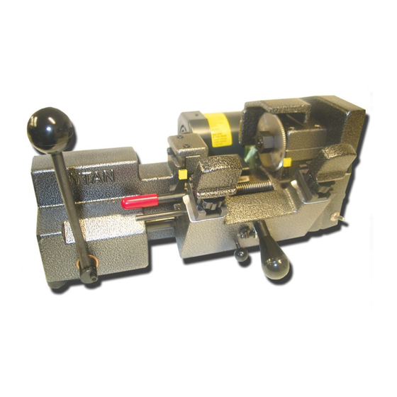
M o d e l R Y 1 0 0
O P E R A T O R ' S
Rytan Model RY100 Semi-Automatic Key Duplicating Machine for
Rytan Products Are Designed and Manufactured in the U.S.A.
READ AND UNDERSTAND THIS OPERATOR'S MANUAL AND BECOME
FAMILIAR WITH YOUR NEW MACHINE BEFORE YOU START CUTTING KEYS
RYTAN, INC. RESERVES THE RIGHT TO MAKE CHANGES WITHOUT NOTICE. PRICES MAY VARY FROM YOUR DISTRIBUTOR
1648 W. 134th St. — Gardena, CA 90249 U.S.A. (310) 328-6553 FAX (310) 212-6002
M A N U A L
RY39 Auxiliary Lamp
RY39 Auxiliary Lamp
Kit is an Extra Cost
Kit is an Extra Cost
Accessory
RY101 Wire Brush
Kit is an Extra Cost
Advertisement
Table of Contents

Related Manuals for Rytan RY100

Summary of Contents for Rytan RY100
- Page 1 FAMILIAR WITH YOUR NEW MACHINE BEFORE YOU START CUTTING KEYS RYTAN, INC. RESERVES THE RIGHT TO MAKE CHANGES WITHOUT NOTICE. PRICES MAY VARY FROM YOUR DISTRIBUTOR 1648 W. 134th St. — Gardena, CA 90249 U.S.A. (310) 328-6553 FAX (310) 212-6002...
-
Page 2: Table Of Contents
TABLE OF CONTENTS INTRODUCTION………………………………………………………………………………………… 4 GETTING STARTED……………………………………………………………………………………. 4 SAFETY RULES………………………………………………………………………………………….4 MOUNTING THE MACHINE…………………………………………………………………………… 5 CUTING STANDARD KEYS…………………………...………………………………………………. 6 CUTTING DEEP CUTS………………………………………………………………………………… 6 VISE JAWS……………………………………………………………………………………………….7 TOP SHOULDER GAUGING……………………………………………….………………………….10 CLAMPING KEYS………………………………………………………….……………………………10 TIP GAUGING………………………………………………………………..………………………….13 RELEASING THE CARRIAGE……………………………………………..………………………….13 CUTTER SHAFT LOCK……………………………………………………..………………………….14 REMOVING/REPLACING CUTTER…………………………………………..………………………15 DEPTH ADJUSTMENT……………………………………………………..…………………………..15 SPACE ADJUSTMENT………………………………………………………..………………………..18 KEY GAUGE ADJUSTMENT…………………………………………………...………………………21 CARRIAGE OVER TRAVEL ADJ…………………………………………...………………………….22... -
Page 3: Introduction
Your new RY100 key duplicating machine is made similar to the RY256 RAMM semi-automatic key machine, but with one exception: Stylus and Cutter Head cannot be rotated to cut Medeco Level-1 high security keys. -
Page 4: Mounting The Machine
L. Secure keys properly in vises. Don’t hold key head for support when cutting. If it doesn’t clamp properly, don’t try to cut it! M. Maintain a sharp cutter wheel. A dull cutter wheel is not only inefficient but dangerous. A dull cutter wheel can produce excessive cutting force on a key blank and exceed the machine’s vise jaws clamping force to a point where the key blank could be ripped out of the machine. -
Page 5: Cuting Standard Keys
D. Always cut keys from Bow-to-Tip. NEVER MAKE YOUR FIRST CUT FROM TIP-TO-BOW. The RY100 is specifically designed to cut most cylinder keys and U.S. and Foreign automotive keys by operating the machine’s “stick-shift” lever SMOOTHLY from Right-to-Left. The key will be cut properly starting at the Bow and ending at the tip of the key. -
Page 6: Vise Jaws
A. Keys are always gauged with the full-function flip-up key gauges. B. Always remember to Flip Down your key gauges before cutting a key. Failure to do so may damage the key gauge and key gauge shaft with the cutter wheel. C. - Page 7 Ford double-sided and when using the step jaw - especially when cut- ting Medeco keys on a Rytan RY256 RAMM key duplicating machine for standard and Medeco keys. Always change both vise jaws to standard or the step jaw configuration. If you change only one – your depth of cut will be off either plus .037”...
-
Page 8: Top Shoulder Gauging
TOP SHOULDER KEY GAUGING LEAVE ABOUT 1/32” GAP BETWEEN BOTTOM SHOULDER Fig. 5 Standard cylinder keys should always be top shoulder gauged. Use the machine’s full-function flip-up key gaug- es. We do not recommend bottom shoulder gauging because key blank manufacturers do not always maintain a reliable correlation between bottom and top shoulder positions on the key blanks they make. - Page 9 TOP PLATE INDEX MARK Top Vise Jaw Replacement Knurled Knob Fig. 3 Fig. 4 Reinstall the top plate with the (4) #6 – 32 x ½” screws flush with the top of the top plate - but do not tighten the four screws at this time.
- Page 10 When both keys have been properly gauged and clamped in the vise jaws REMEMBER to flip down the full-function key gauges before attempting to cut the key. Failure to flip down the key gauges may damage the key gauge and key gauge shaft with the cutter wheel. See figure 7. LEFT VISE JAW Fig.
- Page 11 Door and trunk key “ridge” will contact the face of the BOTTOM vise jaw. See figure 9. STANDARD TOP JAW ALIGN TOP JAW TO BOTTOM JAW PUSH DOOR KEY Ridge of key must contact face bottom vise jaw. Open vise jaws ONLY enough to allow thinnest sec-...
-
Page 12: Tip Gauging
BEST AND FALCON (BEHIND THE TIP) KEY GAUGING These keys must be gauged from a “tip” location that is behind the actual tip of the key. Position the key in the vise so that the “tip” edge of the key is about 1/32” (or less) from the right edge of the vise jaws. -
Page 13: Cutter Shaft Lock
Fig. 13 ALWAYS REMEMBER to flip down your key gauges before cutting a key. Failure to do so may damage the key gauge and key gauge shaft with the cutter wheel. PLEASE. . . DON’T FORGET to turn off your key machine before removing a cut key and reloading another key blank. -
Page 14: Removing/Replacing Cutter
Press DOWN firmly on the cutter shaft lock. While holding the lever down - rotate the cutter by hand until the cutter shaft lock “clicks” in to position. When turning the cutter by hand there is only ONE locking position to be found. Once the cutter shaft lock is fully depressed - Hold it There. You may now proceed with removing the cutter shaft lock nut and the cutter. - Page 15 Depth Adjust- Cutter Shaft Lock Power Switch Fig. 16 To adjust the depth you will need: 5/32” Allen Hex Wrench Piece of writing paper cut to approximately 1” x 4” Two identical key blanks-measure blade width with micrometer or calipers and select two that match. To begin the adjustment you must loosen the two #10-32 Screws.
- Page 16 To begin the adjustment you must loosen the two #10-32 Screws. Use your 5/32” Allen Hex Nut Wrench to loosen the two screws about 1 turn each. Use your hand to turn the knurled thumb-turn adjustment knob about 1 full turn - viewed from the front of the machine you will turn the knob to your LEFT.
-
Page 17: Space Adjustment
Fig. 18 SPACE ADJUSTMENT Never adjust the spacing without first adjusting DEPTH. If the depth adjustment is not right - then spacing will not be right. See #14 above for depth adjustment. Spacing is adjusted by moving the cutter wheel and its cutter shaft assembly left or right. The cutter shaft assembly is secured tot he machine’s main housing by two #10 –... - Page 18 Before you begin please make sure that both top vise jaws are in the standard configuration. See figure 20. STANDARD TOP JAW CONFIGURATION Fig. 20 Stack the two identical key blanks one on top of each other and clamp them in the right hand vise jaw. Be sure to top shoulder gauge them with the machine’s flip-up full-function key gauges –...
- Page 19 Reinstall the TOP key blank in the Right vise jaw with about 1/32” gap between the bottom shoulder of the key and the left-edge of the vise jaw. Install the BOTTOM key blank in the left vise jaw - flip up the machine’s full-function key gauges and carefully top shoulder guard the left key to the key in the right-hand vise jaw.
-
Page 20: Key Gauge Adjustment
Switch OFF the key machine. Tighten the two screws using the 5/32” Allen Hex Wrench IMPORTANT – Verify that your depth adjustment is correct and readjust if necessary. Refer back to page 15 regarding Depth Adjustment if necessary. KEY GAUGE ADJUSTMENT Stack two identical key blanks one on top of the other and clamp in the right-hand vise jaw. -
Page 21: Carriage Over Travel Adj
CARRIAGE OVER TRAVEL DEPTH ADJUSTMENT Your key machine is equipped with a depth over travel device. Its adjustment is important. The over travel device prevents the cutter wheel from cutting into the vise jaws when there are no keys clamped in the ma- chine. -
Page 22: Maintenance
Your machine is time proven with good design, engineering and modern manufacturing practices. You can ser- vice virtually this key machine. Because Rytan manufactures the machines in-house you are assured a supply of new re- placement parts and updates for as long as YOU want us to make the machines. - Page 23 MOTOR MOUNTING SCREWS Fig. 25 KEY MACHINE ACCURACY Generation Cutting Generation cutting is a process where the key machine operator takes a fresh cut key and duplicates another key off of it, then takes that freshly cut key and duplicates another from it, and so on. The idea is to cut as many “generations”...
-
Page 24: Troubleshooting
TROUBLESHOOTING Machine Always Needs Adjustment There are several things that can cause your machine to need adjustment. 1. Cutter wheel may be dull. This can cause the key to try to ―float‖ and not cut deep enough in the deepest cuts. - Page 25 5. You’re in your service vehicle. You’re Redi-Line generator needs repair, or your wiring needs replacing (usually from the battery to the Redi-Line), or your battery is weak. Another possibility is that you’ve been using a power converter and it is marginal. 6.
- Page 26 2. Key cuttings in the motor’s capacitor. Unplug the machine, remove the capacitor’s rubber cover and blow out the chips. Remember to wear safety glasses. 3. Remove the machine’s access plate—check the wiring connections and switch. Repair or replace as nec- essary.
- Page 27 Replace the cutter wheel when deburring the key seems to take longer than normal. Replace the cutter wheel when you find yourself “assisting” or “force-feeding” the carriage more often, especially in deep cuts. NOTE: Rytan’s key machine cutter can be resharpened. Call us for de- tails.
- Page 28 Remove the left-hand nut and cutter wheel. Remove the access plate and wire brush if installed on your RY100 and loosen the four motor mounting screws to loosen the drive belt. Loosen the two #10-32 socket head cap screws located on the top front edge of the cutter head – use your 3/16” Allen hex wrench. Loosen them about 1 full turn each.
-
Page 29: Customer Information
Rytan, Inc. provides the following information on warranty and service for the RY100 key duplicating machine: Warranty Registration The Warranty Registration Form must be filled out and mailed to Rytan, Inc. within TEN days of date of pur- chase. Failure to do so will VOID the warranty. -
Page 30: Warranty
WARRANTY WARRANTIES (APPLICABLE IN THE CONTINENTAL U.S.A. ONLY) RYTAN, INC. MODEL RY100 KEY MACHINES ARE WARRANTED TO BE FREE FROM MANUFACTURING DEFECTS FOR ONE YEAR FROM DATE OF PURCHASE. DURING THE FIRST YEAR DEFECTIVE PARTS WILL BE REPLACED WITHOUT CHARGE FOR PARTS OR LABOR. MACHINES MUST BE RETURNED TO THE RYTAN, INC. -
Page 31: Parts Breakdown
Rake and Miniature pick tips are, and always be, uniquely ours. Did you know that once you become accustomed to the comfort and “feel” of the Rytan curved pick handle it is hard to go back to the straight handle again. - Page 32 70-RY9059 Shoulder Screw 30-RY10029 Stylus Adjustment Knob RY20006 Knob assb. w/ bearing 71-RY10020 Drive Link 31-RY9056 Nylon Lock Nut Covert your RY100 to 4-way jaws RY20028 Stylus 72-RY10019 Drive Shaft 32-RY10028 or RY20028 Stylus RY20030 Cutter for RY200 75-RY10022 Carriage Shaft...
Need help?
Do you have a question about the RY100 and is the answer not in the manual?
Questions and answers