Table of Contents
Advertisement
Advertisement
Table of Contents

Related Manuals for CASSENS & PLATH NETcourse

Summary of Contents for CASSENS & PLATH NETcourse
- Page 1 Installation & Operation Manual NETcourse Magnetic Compass Converter CASSENS & PLATH GmbH Manufacturers of Nautical Instruments Am Lunedeich 131 D-27572 Bremerhaven, Germany Tel. +49 471 483 999 0 Fax +49 471 483 999 10 sales@cassens-plath.de www.cassens-plath.de...
-
Page 2: Table Of Contents
NETcourse Page 2 Content 1) Drawings 1.1) Dimensions 1.2) Mounting of Control Unit 1.3) System Overview 1.4) Control Unit, Front Controls 1.5) Control Unit, Front Push Buttons 1.6) Control Unit , Rear 2) Menu-Mode 2.1) Menu “Load Default Errorlist” 2.2) Menu “Set Up Errorlist“... -
Page 3: Drawings
NETcourse Page 3 Drawings 1.1) Dimensions Flush mounting: 145 mm 120 mm 220 mm 245 mm Weight: 2,1 KG 1.2) Mounting of Control Unit Flush mounting (cut-out: 225 mm x 125 mm): 85 mm min. 110 mm 235 mm Alterations/Errors reserved 15/Wo/251D Cassens &... -
Page 4: System Overview
NETcourse Page 4 1.3) System Overview Compass Mounting cylinder Detector CP102B Detector cable 1,5 m (5-wires, screened) with connector Junction box Detector cable 15 m (5-wires, screened) with connector Control Unit RS-485 Data output with connector Emergency power supply 24VDC, 4m (2-wires) -
Page 5: Control Unit, Front Controls
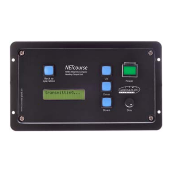
NETcourse Page 5 1.4) Control Unit, Front Controls: ERROR 1) LC-Display 2) On/Off switch 3) Dimmer LC-Display shows actual functions, Menus or error messages On/Off switch Backlight dimmer of LC display Alterations/Errors reserved 15/Wo/251D Cassens & Plath GmbH, Am Lunedeich 131, D-27572 Bremerhaven, Germany, tel. +49 471 483 999 0, fax +49 471 483 999 10 www.cassens-plath.de,... -
Page 6: Control Unit, Front Push Buttons
NETcourse Page 6 1.5) Control Unit, Front Push Buttons: “Back To Operation“ LC-Display “Enter” “Up/Down” push botton push botton push bottons “Back To Operation“ push botton Return to operation mode “Up/Down” push botton Moves Menu one step up or down “Enter“... -
Page 7: Control Unit, Rear
NETcourse Page 7 1.6) Control Unit, Rear Grounding Detector RS-485 output Emergency voltage Main voltage Alterations/Errors reserved 15/Wo/251D Cassens & Plath GmbH, Am Lunedeich 131, D-27572 Bremerhaven, Germany, tel. +49 471 483 999 0, fax +49 471 483 999 10 www.cassens-plath.de,... -
Page 8: Menu-Mode
Transmission error is the difference of the direct reading of the magnetic compass and the heading as displayed by NETcourse. This Menu item enables you to establish a errorlist. This is only necessary in case too large transmission errors are recognized. These transmission errors are caused by the direct interference of the corrector magnets to the detector, so these errors are not a malfunction of the instrument but they result from the ship´s magnetic iron resp. -
Page 9: Menu "Transmission Protocol
With this menu item the alignment of detector can be executed. For installation of NETcourse it is necessary to align the detector to the magnetic compass. For alignment loosen screws of detector a little bit, so that detector can be turned slightly. -
Page 10: Error Messages / Error Removing
Make sure wiring and right voltage supply. No data transmission. Make sure that data cables and connectors NETcourse shows no are in order. error message. Interchange data cable A and B. Make sure that correct output data specification was selected. -
Page 11: Installation
NETcourse Page 11 Installation 4.1) Installation of Detector This chapter may be passed in case the detector is already installed to the compass when delivered. As heading source a conventional compass has to be used. Installation of detector is usually done by glueing it from below centric to the lower cover glass. Between detector and lower cover glass of the compass a certain distance has to be kept. -
Page 12: Installation Of Junction Box
NETcourse Page 12 4.2) Installation of Junction Box The junction box allows easy removal of the compass from the binnacle and easy separation of detector cable. 4.3) Location of Detector and Junction Box within Compass Binnacle: Hood Compass Detector Distance Cylinder... -
Page 13: Wiring
NETcourse Page 13 Wiring: 5.1) Power Supply brown + Mains green brown + green Emergency 5.2) Connection of Junction Box Connect color to color green gray white brown pink 5.3) Connection of Data Output White Data A Green Data B... -
Page 14: Extension / Shortening Of Detector Cable
Grounding Although NETcourse has passed EMC qualification tests according to EN 60945, an accurate grounding is necessary to avoid interferences caused by electromagnetic radiation like UHF or VHF and electromagnetic pulses (EMP). For example radio telefones are known to disturb the function of the electronics. -
Page 15: Start-Up Operation
NETcourse Page 15 Start-up Procedure 7.1) Check the Power Supply Check power supply voltage 24 VDC (main- & emergency) with multimeter (ref. to page: “Pin Connection of Plugs/Connectors”) 7.2) Start Instrument and Check Operation Switch on the instrument after having completed installation works. -
Page 16: Pin Connection Of Plugs/Connectors
NETcourse Page 16 8) Pin Connection of Plugs/Connectors (As to be seen from rear of casing) Power Supply (3-pin): (24VDC, identical for mains & emergency supply) 2) not connected 1) +24VDC (brown) 3) Ground (green) Detector (5-pin): 3) Reference (white)
Need help?
Do you have a question about the NETcourse and is the answer not in the manual?
Questions and answers