Advertisement
Quick Links
中文说明书
........................................................................................................................ 1-8
English User Manual
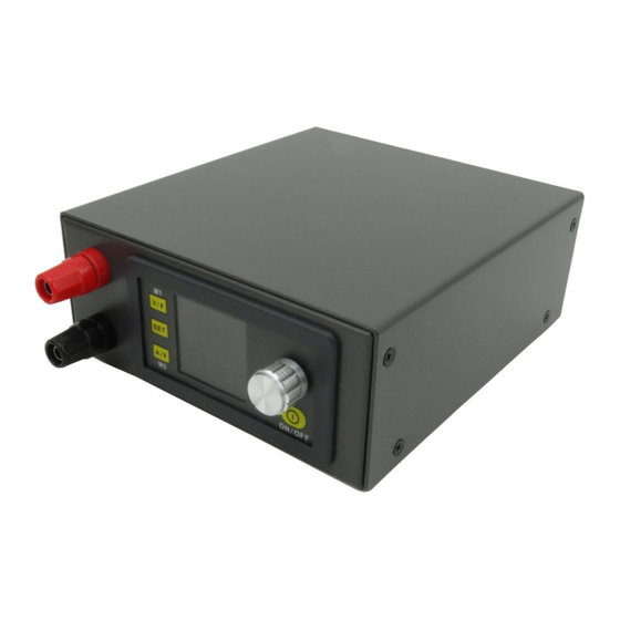
通信版数控电源钣金外壳安装说明
外壳适用数控电源型号:
DPS5015 ( DPS5015-USB) 、 DPS5020 ( DPS5020-USB) 、 DPS3012、 DPH3205
一、 安装注意事项:
⚫ 安装前请仔细阅读本文档,如有疑问请与本公司联系。
⚫ 本外壳采用冷轧钢板材料,表面喷塑,安装、使用时应防止尖
锐物体划伤,避免阳光直晒和潮湿环境。
⚫ 组装时防止短路,正确连接正负极。
⚫ 不可在电源接通的情况下连接电路。
......................................................................................................... 9-14
- 1 -
Advertisement

Related Manuals for RD DPS5015


Summary of Contents for RD DPS5015
- Page 1 中文说明书 ........................1-8 English User Manual ......................9-14 通信版数控电源钣金外壳安装说明 外壳适用数控电源型号: DPS5015 ( DPS5015-USB) 、 DPS5020 ( DPS5020-USB) 、 DPS3012、 DPH3205 一、 安装注意事项: ⚫ 安装前请仔细阅读本文档,如有疑问请与本公司联系。 ⚫ 本外壳采用冷轧钢板材料,表面喷塑,安装、使用时应防止尖 锐物体划伤,避免阳光直晒和潮湿环境。 ⚫ 组装时防止短路,正确连接正负极。 ⚫ 不可在电源接通的情况下连接电路。 - 1 -...
- Page 2 ⚫ 尽量避免震动和跌落。 二、 产品规格 2.1 装配爆炸图: - 2 -...
- Page 3 2.2 器件清单: 名称 规格 数量 备注 上盖 137*123*51 冷轧钢板 底壳 MM(长*宽*高) 风扇 4010 5V 供电 风扇供电板 36*40(长*宽) 红色 2 个黑 接线端子 M4*36 色 2 个 冷压端子接头 UT2.5-4 U 型插接头 船型开关 KCD3 RV2.5 平方单芯 红:30cm 连接电线 软线 黑:25cm 外壳配套螺丝 平头 M3*5 M3 单头六角尼龙...
- Page 4 备注: 外壳配套螺丝 尼龙支撑柱 M3 单头六角 风 扇 固 定 螺 功率模块、通 冷 压 端 子 接 信板固定螺丝 头 UT1-4 M3*5 8 个 尼龙柱 L=8mm、尼龙螺母 栓 圆 头 圆头 M3*5 共 7 个 M3 六角尼龙螺母 H=2.4mm M3*13 4 个 6 个 三、...
- Page 5 3.1 安装准备: ⚫ 数控电源模块一个。 ⚫ 工具(电烙铁、焊锡、十字螺丝刀、剥线钳等) 。 ⚫ 适当的安装环境。 3.2 安装步骤: a) 使用剥线钳截取适当长度的电线,电线长度参考下图: b) 安装输入接线端子及开关(将接线端子和开关卡在后面板留出 的卡槽上,接线端子采用上正(红)下负(黑)的原则安装, 固定螺丝要拧紧) - 5 -...
- Page 6 c) 安装风扇供电板: ⚫ 将风扇电源线焊接到风扇供电板正面左下方的 5V 焊盘上 (注意正负极不要焊反) 。 ⚫ 将电源输入线焊接在风扇供电板左上角的两个焊盘上, (注 意正负极不要焊反) 。 ⚫ 将供电板安装在后面板的接线端子上 (注意正负接口) , 然 后使用螺母固定。 ⚫ 将电源开关用预先准备好的连接线焊接在供电板 Key 处焊 盘上。 d) 安装散热风扇(注意采用配套的螺栓固定,风扇贴有指示标签 的一侧朝外,不可装反) - 6 -...
- Page 7 e) 安装好输出接线端子, 将准备好的带有冷压端子的输出线连接到 输出接线端子上,并用螺母拧紧(输出端子上正下负安装,输出 线不要接错) f) 本外壳针对的产品分为显示部分、功率部分、USB 通信部分,安 装过程为: ⚫ 首先安装通信部分 (如果产品不附带通信功能, 本步骤忽略) , 使用尼龙支撑柱和尼龙螺母把通信板支撑起来,然后使用通 信板固定螺丝将其固定在底壳预定位置上 - 7 -...
- Page 8 ⚫ 安装显示模块将其卡入前面板卡槽上 (卡入过程用力要适当, 防止造成前面板变形) 。 ⚫ 安装上显示模块和功率模块连接的排线,注意 PCB 板的丝印 层 LCD 和 KEY 排线插接的位置(排线一定走 PCB 板的下方, 否则电感会对其有干扰) 。 ⚫ 根据下盖板四个孔的位置安装功率模块,使用配套螺丝将其 固定住。 ⚫ 将输入正负分别接到功率模块的 IN+,IN-;输出正负接到 OUT+,OUT-。 ⚫ 通过通信板连接线连接通信板与功率板 g) 连接好之后可以通电看是否连接成功。 (注意通电前再次检查接 线是否正确) h) 安装上盖,将上盖装配到下壳,采用配套螺丝固定 i) 本产品配套四个透明脚垫, 用户可对称粘贴到外壳底部四个角上。 3.3 内部连线图: - 8 -...
- Page 9 Digital Control Power Supply Housing Installation Instructions This housing is suitable for the following mode of digital control power supply: DPS5015(DPS5015-USB-BT) 、DPS5020(DPS5020-USB-BT) 、DPH5005(DPH5005-USB-BT)、 DPS3012、DPH3205 1. Installation Note: 1.1 Please read the instructions carefully before installation. If you have any question, please contact us.
- Page 10 2.1 Product Assembly Explode Diagram 2.2 Kit parts list Item Specification Qty. Remark Upper cover plate 137*123*51 Cold-Roll Steel Sheets Lower cover plate MM(L*W*H) 4010 5V power supply Fan power supply board 36*40(L*W) Red 2pcs Binding post M4*36 Black 2pcs Cold press connecting...
- Page 11 Power module communication board fixing Fillister head M3*5 screw Φ12*4 Transparent sticky mat 2.3 Kit Parts Picture 1- Lower cover plate 2- Fan Connecting line 4- Transparent sticky mat Fan power supply board 6- Rocker Switch Binding post 8- Power module and communication board fixing screw 9- Cold press connecting terminal 10- Screw for housing...
- Page 12 3.2.1 Use wire stripping pliers to cut proper length line, the length as follows: 14- Fan line 45mm 15- Switch connecting line 35mm Output positive line 50mm Output negative line 60mm 18- Input positive and negative connecting line 150-180mm 19- Output positive line 60mm 20- Output negative line 70mm 21- Input positive and negative connecting line 3.2.2 Install the input binding post and...
- Page 13 below), then use the screw to fix them. 3.2.3.4 Use the prepared wire to weld the power switch on the key place at fan power supply board. 3.2.4 Install the fan: use the matched screw to fix. The one side attached label is installed outward.
- Page 14 3.3 Internal connection diagram: - 14 -...
Need help?
Do you have a question about the DPS5015 and is the answer not in the manual?
Questions and answers