Advertisement
Quick Links
Advertisement

Related Manuals for Robotics V3

Summary of Contents for Robotics V3
- Page 1 How to Build the Robotics++ V3 Robot...
- Page 2 All material and assembly guide can de downloaded from WWW.ROBOTICSCITY.COM Pages Password : r2d2 Note: Experiments are updated constantly with new sample programs, references and new sensors reviews. Robot Kit Version: Update Date: 9/28/2016 Part Description Sensors and CPU Arduino Uno R3 Arduino UNO R3 computer board with DC-DC converter USB Programming Cable USB Programming Cable...
- Page 3 Put your screws on this template to help you inventory and determine size...
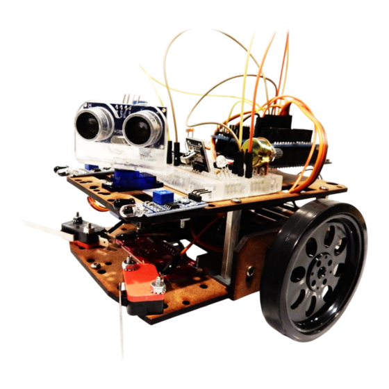
- Page 4 Completed Robotics++ V3 Robot. More views of completed robot can be found at the end of this instructions manual The fun starts now!
- Page 5 V3 Kit Parts Note: Some kits will come with plastic brackets for the wheel servo motor assemblies. Moisture sensor might be red color rather than black as shown here.
- Page 6 Graphical Parts List...
- Page 7 Graphical Parts List DC-DC 9V to 5V converter...
- Page 8 Graphical Parts List...
- Page 9 Graphical Parts List Resistors color code: 220 Ohm – Red, Red, Brown 1K Ohm- Brown, Black, Red 10K Ohm – Brown, Black, Orange Potentiometer is 10K Ohm...
- Page 10 Extra Electronic Components are meant to be used when doing the Electronics Note: There are two kind of 101 – (10 Extra Projects) See link below for instructions moisture sensors. You will get http://www.roboticscity.com/electronics101.html whichever one we have in stock 10K Ohm Potentiometer 3-6V DC Motor 1N4007 Diode...
- Page 11 Graphical Parts List SUMO Parts: (2) Plastic L brackets (1) Lasercut ramp Note: Some laser cut parts will still have remaining chads. Please use your start or mini screwdriver to pop-out the chads as seen on the right.
- Page 12 Step 1: Assembling the Servo Motors Parts: (2) Servo motors (8) 1/2” pan head screws (8) Lock nuts screwdriver (4) Metal or plastic servo holder L brackets (2) Laser cut servo holders (1) Screwdriver Note: You may also refer to the pictorial parts list to learn more about the names of each component...
- Page 13 Step 1: Assembling the Servo Motors – for kits with plastic L brackets - Continued Parts: (2) Servo motors (8) 1/2” pan head screws (8) Lock nuts screwdriver (4) plastic servo holder L brackets (2) Laser cut servo holders (1) Screwdriver...
- Page 14 Insert the servo motors into the servo holders and secure them with the 1/2” screws and nuts as shown on the right photo. Please take careful note and on the next page: - how the motors are inserted into the servo holders - how the screws face in on the servo holders - how the shaft of the motor is facing on the front on both left and right sides.
- Page 15 Backside of servo assemblies Notice how the position of the shaft on each servo holder is on opposite ends. One will be on the left and the other on the right...
- Page 16 Step 2: Assembling the metal or plastic servo holder L brackets Parts: (4) metal locking nuts (4) 3/8 screws (4) metal or plastic brackets (1) star screwdriver...
- Page 17 Paying attention to the direction the screw goes in, assemble the metal L brackets as shown below on both servo holders. To align the brackets you can hold the assembly against a flat surface then tighten the screws. Note: you do not raise the L brackets your wheels will be too high and the robot will not move so see photo below for how the metal brackets go.
- Page 18 If you have the plastic L brackets be sure to install them on the upper hole as shown below...
- Page 19 Step 3: Assembling the Line Following Sensor Parts: (2) metal locking nuts (2) 3/4 screws Servo Red line following sensor Horns Lower laser cut chassis star screwdriver Servo horns from one of your 360 rotation servos We will use the plastic servo horns as spacers to ensure the line following sensor is low enough or closer to the floor so...
- Page 20 Follow the photos below to install the sensor using the 3/4” screws. Use the servo motor horns as spacers.
- Page 21 Installing front acorn nut Parts: Using a 1/2” pan head screw and lock - (1) 1/2” pan head nut proceed to install as shown below. screw Note: - (1) lock nut - Try to tighten the acorn nut as much - (1) acorn nut as possible Acorn nut with ½”...
- Page 22 Step 4: Assembling the “Feeler” (switches) Sensors The feeler sensors are mechanical momentarily ON switches that when pressed it completes the circuit and can trigger a response. These are secondary sensors in case our other sensors do not work. Note: If you are building the Sumobot (Experiment 8) first then skip to Step 5.
- Page 23 Screw switches as shown using Pay attention to the angles the the 3/4” pan head screws switches are positioned at...
- Page 24 Step 5: Assembling the servo motors on lower chassis Parts: - (2) servo assemblies Use 3/8” - assembled lower chassis panhead - (4) 3/8 inch pan head screws screws here - Star screwdriver Note: Go to next page to see how to mount metal spacers Use 3/8”...
- Page 25 Metal spacers assembled lower chassis Use the 3/8" screws for this Install servo assemblies as shown on the top side of the lower chassis using the L brackets and the 3/8 inch screws. Attention! don’t make it too tight yet as you need to assemble upper chassis on top and might require some...
- Page 26 Arduino, Battery Holder and Sensor Shield Connections Make sure you connect your components as shown here The Arduino board has a DC-DC step up converter to stablelize its voltage while under load or moving the robot. There is also a DC- DC step down converter to convert DC-DC Step Down Converter...
- Page 27 Start preparing the parts to mount the battery holder with ON- OFF switch Servo shaft points to front of the chassis Parts: - Battery holder - (1) 3/4” flat head screw - (1) acorn nut - Lower chassis assembly Battery holder with - (1) lock nut ON-OFF switch.
- Page 28 Step 6: Assembling the battery holder and back acorn nut Note: You only will install one screw on the battery holder on the back. You only need one to make it easier to pull out the battery holder and replace batteries when need it 3/4”...
- Page 29 Step 7: Assembling the upper chassis and Arduino board Parts: Use the three nylon spacers and Upper chassis three 1/4” screws and install the - (3) nylon spacers spacers on the Arduino board as - (6) 1/4” screws shown below. Do not tighten yet! - Arduino board - Star screwdriver...
- Page 30 Assembling Arduino board on upper chassis Note: Arduino board can only go in one direction. The holes on the upper chassis match the direction the Arduino board should go Nylon spacer 1/4” screw...
- Page 31 Make sure you have the correct Sensor Shield...
- Page 32 Mounting the Arduino Sensor Shield v5.0 on the Arduino board Parts - Upper chassis - Sensor Shield 5.0 Backside pins Sensor Shield 5.0 Notice position of pins and direction. Start from the back pins to the front pins. The press all the way down.
- Page 33 Step 8 : Mounting the breadboard or protoboard Parts - (1) upper chassis - (1) breadboard - (1) 1” flathead screw - (1) locking nut - Star screwdriver Breadboard Install the breadboard as shown using the 1” flathead screw (see breadboard packaging for this screw).
- Page 34 Step 9: Install 5 AA Batteries as shown below Parts - Lower chassis - (5) AA batteries Note!: we will install the sixth battery once everything is connected...
- Page 35 Step 10: Install Upper Chassis on Metal Spacers Mount the upper chassis to the four metal spacers as show below using the ¼ inch screws. Also install the Arduino Sensor Shield as seen below. Note:- Pull the servo and feeler wires thru the holes as shown below for each side Parts - Upper chassis...
- Page 36 Step 11: Installing the Battery ON-OFF switch and Power Connections Run the red female DuPont wire from the battery holder to the bottom of the Arduino DC-DC converter pin thru the small square on the top chassis as shown on left and right pictures.
- Page 37 Connecting battery cables to the Arduino Sensor Shield Parts Using the small flat screwdriver - Battery pack loosen the screw terminal connectors and insert wires then - Sensor Shield V5.0 screw back in to secure. If - Flat/or star robot turns ON just turn the screwdriver switch to the OFF position Sensor shield...
- Page 38 Reminder:Arduino, Battery Holder and Sensor Shield Connections Make sure you connect your components as shown here The Arduino board has a DC-DC step up converter to stablelize its voltage while under load or moving the robot. There is also a DC-DC step down converter DC-DC Step Down Converter to convert from 9V to...
- Page 39 Insert wheel carefully, but with force to Step 12: Assembling the wheels the shaft of the servo motor. Use only the screws that come in the bag of servo horns. Parts These will make sure to hold the wheels. - (2) wheels - (2) screws from servo motors parts bag to mount wheels - Star screwdriver...
- Page 40 completed chassis and wheels assembly...
- Page 41 Step 13: Mounting the Adjustable Infrared Sensors Parts (2)Adjustable IR sensors (2) 1/2” pan head screws (2) Nylon nuts Star screwdriver Using the nylon nuts and 1/2 “ screws you can mount the infrared sensors in any location you want...
- Page 42 Step 14: Mounting the Micro Servo and Sonar Sensor Parts (1) Small blue micro servo motor (1) Sonar sensor (1) Sonar sensor clear bracket Star screwdriver Sonar sensor Clear sonar sensor holder Micro Servo and mounting screws...
- Page 43 Mount micro servo on top chassis. Make sure motor shaft is facing the front of robot. Carefully screw the servo using the two small screws that came with it. The smallest screw of the three is to secure the sonar sensor clear bracket.
- Page 44 Completed robot with sample components on the breadboard! We are ready to try Experiment 1 Go to the website to download Experiment 1...
- Page 45 Sumo Robot – See Experiment 6 Sumo Robot for assembly instructions when ready...
- Page 46 Sumo Robot...
- Page 47 Completed Robot...
- Page 48 Completed Robot...
- Page 49 Completed Robot...
- Page 50 Completed Robot...
- Page 51 Completed Robot...
- Page 52 Completed Robot...
- Page 53 Completed Robot...
- Page 54 That’s it! Now we can start the experiments to learn how to program the robot with creative algorithms, motor control, basic electronics and sensor interfacing. Please visit http://www.roboticscity.com/ download these exciting projects. Have FUN!
Need help?
Do you have a question about the V3 and is the answer not in the manual?
Questions and answers