
Related Manuals for WaterGroup 6200SXT Upflow

Summary of Contents for WaterGroup 6200SXT Upflow
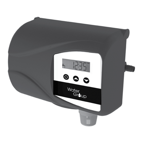
- Page 1 Service Manual 6200 SXT Upflow Control Valve for Water Conditioning and Treatment Purposes...
-
Page 2: Table Of Contents
Table of Contents Job Specificaton Sheet and Valve Specifications ..........................X Installation Instrucitons 6200SXT Upflow ..............................X Startup Instructions ....................................X Timer Features ......................................X Timer Operation ...................................... X Master Programming ....................................X User Programming ....................................X Diagnostic Programming Mode ................................X Service Kits ....................................... - Page 3 Job Specitication Sheet Valve Specifications Job Number: __________________ Valve Specifications Model Number: ________________ Valve material Fiber-reinforced ploymer Water Hardness: ___________________ ppm or gpg Inlet/Outlet 3/4” - 1” NPT, BSP, Sweat Capacity Per Unit: ______________ Cycles Up to 5 cycles Mineral Tank Size: ___________ Diameter: ___________ Height: Flow rates (50 psi Inlet) - Valve Alone (GPM) Salt Setting per Regeneration: ___________________________________ __________...
-
Page 4: Installation Instrucitons 6200Sxt Upflow
Installation Instructions 6200SXT Upflow WATER PRESSURE: A minimum of 20 psi (1.4 bar) of water pressure is required for regeneration valve to operate effectively. ELECTRICAL FACILITIES: An uninterrupted alternating current (A/C) supply is required. Note: Other voltages are available. Please make sure your voltage supply is compatible with your unit before installation. -
Page 5: Startup Instructions
Start-up Instructions The water softener/filter should be installed with the inlet, outlet, and drain connections made in accordance with the manufacturer’s recommendations, and to meet applicable plumbing codes. Please refer to the manual regeneration part of the timer operation section in this manual. 1. -
Page 6: Timer Operation
Timer Operation Meter Immediate Control to operate normally monitoring water usage and keeping all displays up to date. Control programming is stored in A meter immediate control measures water usage and regenerates the system as soon as the calculated system memory permanently, eliminating the need for battery capacity is depleted. -
Page 7: Master Programming
Master Programming Mode Chart Master Programming Options Option Abbreviation Parameter Options Abbreviation Gallons Display Format Liters df1b Standard Downflow/Upflow Single Backwash df2b Standard Downflow/Upflow Double Backwash Valve Type Fltr Filter UFbF Upflow Brine First (use for 6200 upflow softener valve) UFtr Upflow Filter (used for 6200 upflow filter valve) Meter (Flow) Delayed... - Page 8 Master Programming Mode When the Master Programming Mode is entered, all Display Format Setting Unit of Volume Time Display available option setting displays may be viewed and set U.S. Gallons 12-Hour AM/PM as needed. Depending on current option settings, some Liters 24-Hour parameters cannot be viewed or set.
- Page 9 Master Programming Mode identified by “SF” in the 5. Unit Capacity (Display Code C) upper left hand corner of the Press the Extra Cycle button. Use this display to set the Unit screen. Use the Up and Down Capacity. This setting specifies the treatment capacity of buttons to adjust the value the system media.
- Page 10 Master Programming Mode 12. Regeneration Cycle Step Times 15. Current Day (Display Code CD) Press the Extra Cycle button. Use this display to set the Press the Extra Cycle button. Use this display to set the current day on systems that have been configured as Day Regeneration Cycle Step Times.
-
Page 11: User Programming
User Programming Mode User Programming Mode Options Abbreviation Parameter Description Day Override The timer’s day override setting The time of day that the system will regenerate (meter Regeneration Time delayed, timeclock and day-of-week systems) The hardness of the inlet water - used to calculate Feed Water Hardness system capacity for metered systems Reserve Capacity... -
Page 12: Diagnostic Programming Mode
Diagnostic Programming Mode Diagnostic Programming Mode Options Abbreviation Parameter Description Flow Rate Displays the current outlet flow rate Peak Flow Rate Displays the highest flow rate measured since the last regeneration Hours in Service Displays the total hours that the unit has been in service Volume Used Displays the total volume of water treated by the unit Displays the system’s reserve capacity calculated from the system... - Page 13 6200 Service Kits – Piston and Cartridge Assembly Dwg # Part # Part Description O-Ring 97 61799-01 Cartridge Assembly with Piston O-Ring 98 11335 Screw, 4-40X3/16 Blank 16394 O-Ring, 029 REVISIONS 13287 O-Ring, 123 ZONE REV. DESCRIPTION DATE APP'D Blank 61799 Seal and Spacer Cartridge 42920...
- Page 14 6200 Service Kits – Brine Line Flow Control Kits Dwg # Part # Part Description 13302 O-Ring, 014 10141 O-Ring, 010 17307 Washer, Flow, 0.125 GPM 12094 Washer, Flow, 0.25 GPM 12095 Washer, Flow, 0.5 GPM 12097 Washer, Flow, 1.0 GPM 19334 Retainer, Flow Washer, BLFC 19335...
- Page 15 6200 Service Kits – Flow Meter Dwg # Part # Part Description 19791-01 Cable, Meter 19569 Clip, Flow Meter 13314 Screw, Slot Hex, 8-18 X0.6 19797 Meter, Assy,3 /4" Dual Port 13305 O-Ring, -119 14613 Flow Straightener 60626 Meter Only, Electronic Turbine 6200 Service Kits –...
- Page 16 6200 Service Kits – Circuit Board Dwg # Part # Part Description 19474-01 Harness, Power, SXT 19791-01 Cable Meter 42766-02 Circuit Board, SXT 17020 Screw 6200 Service Kits – Other Parts Dwg # Part # Part Description 17020 Screw, Stl Hex, 6-20 X 3/8 040050 Screw, Hex Washer 42919...
- Page 17 6200 Service Kits – Other Parts Continued Dwg # Part # Part Description 43052-01 Cover, Black 43052-02 Cover, Cream 10231 Screw, Slot Hex, 1/4-20 X 1/2 19597 Motor, 24V, 50/60 Hz 43053-01 Backplate, Black 43053-02 Backplate, Cream 19581 Bracket, Drive 10302 Insulator, Limit Switch 019688...
- Page 18 Bypass Valve Assembly & Yokes (Plastic) Item No. Quantity Part No. Description 13305 O-ring, -119 13255 Clip, Mounting 13314 Screw, Hex Washer Head, 8-18 x 5/8 18706 Yoke, Plastic, 1” NPT 18706-02 Yoke, Plastic, 3/4” NPT 13708 Yoke, Brass, 3/4” NPT 13708NP Yoke, 3/4”...
-
Page 19: Flow Diagrams
Water Conditioner Flow Diagrams Service Position Backwash Position Hard Water Hard Water Soft Water Soft Water Hard Water Hard Water Soft Water Soft Water To Drain To Drain To Drain To Drain Hard Water Soft Water Hard Water Soft Water Brine Rinse Position Slow Rinse Position Hard Water... - Page 20 Water Conditioner Flow Diagrams Rapid Rinse Position Brine Refill Position Hard Water Soft Water Hard Water Soft Water To Drain To Drain...
-
Page 21: Wiring Diagram
Wiring Diagram... -
Page 22: Upflow Brining Rates
6200SXT Upflow Brining Rates 6200SXT Upflow Brining Rates with Water- 20 PSI Regulated Cap... - Page 23 Servicing 6200 SXT Upflow Control Valve – Replacing Injectors and Screen 4. Apply silicone lubricant to the gasket and install Valve Body around oval extension on injector cap 5. Apply silicone lubricant to Disperser two new o-rings and install Disperser over 2 bosses of the new Screen injector assembly.
- Page 24 Replacing Brine Valve Front Cover 1. Open the front cover of the powerhead, unscrew the brine cam and push the brine valve in order to remove the cam. 2. Remove the two screws from the grey brine valve bracket and remove it from the valve back plate. 3.
- Page 25 Timer Replacement Meter Cable Screw Self tapping screw Screw Brine Valve Brine Cam Bracket 1. Disconnect the meter cable from the 2. Open the front cover of the control 3. Remove the two screws from the meter. valve, unscrew the brine cam and grey brine valve bracket and re- push the brine valve in order to re- move it from the valve back plate.
- Page 26 Piston Cartridge Assembly Replacement All 5 O-rings need to be inspected for damages REVISIONS REV. DESCRIPTION DATE APP'D ZONE and lubricated LAST SAVED IN SMARTEAM: DATE AND TIME CRITICALITY SYMBOLS PER QPSP-001.2 THE COMPONENT, PART, OR ASSEMBLY DESCRIBED IN THIS DOCUMENT MUST COMPLY WITH THE EU (EUROPEAN UNION) DIRECTIVE: LEVEL I LEVEL II LEVEL III...
- Page 27 Servicing and Replacing Brine Line Flow Control (BLFC) 1. Disconnect the brine line retainer 2. Remove the BLFC assembly and pull 3. Remove the flow washer from the clip the flow washer retainer out of the retainer and clean it with water to BLFC housing with then help of plier.
- Page 28 Circuit Board Replacement Screws Meter Cable Power Harness 1. Detach the circuit board from valve 2. Disconnect the meter cable and 3. Replace and connect the new cir- front cover by removing two screws power head harness from the circuit cuit board on the front cover.
-
Page 29: 6200 Sxt Valve Dimensional Drawing
6200 SXT Valve Dimensional Drawings All dimensions are in Inches (mm). - Page 30 6200 SXT Control Valve Exploded View...
- Page 31 6200 SXT Powerhead Exploded View Replace with in lter valve O-Ring No O-Ring O-Ring No O-Ring in case of lter valve...
- Page 32 6200 SXT Parts List Item No. Qty. Part No. Description Item No. Qty. Part No. Description 19344-05 ADAPTER BASE, 6200 13363 WASHER, HAGUE DRIVE 13030 RETAINER, DISTRIBUTOR 40058 SCREEN, INJECTOR 43054-03 LABEL, NOVATEK 6200, GREEN 13304 O-RING, -121 19197 RING, SLIP 43054-01 LABEL, DURO 6200, BLUE 40079-20...
-
Page 33: Troubleshooting
Troubleshooting Problem Cause Correction 1. Water conditioner A. Electrical service to unit has been A. Assure permanent electrical service (check fuse, fails to regenerate. interrupted plug, pull chain, or switch) B. Timer is defective. B. Replace timer. C. Power failure. C. -
Page 34: Error Codes
Troubleshooting - Error Codes Error Codes Note: Error codes appear on the In Service display. Error Code Error Type Cause Reset and Recovery Cam Sense The valve drive took longer Unplug the unit and examine the powerhead.Verify Error than 6 minutes to advance that all cam switches are connected to the circuit to the next regeneration board and functioning properly. - Page 36 U.S. Headquarters WaterGroup Companies, Inc. 193 Osborne Road Fridley, MN 55432, USA 1-877-581-1833 TOLL FREE PHONE: Canada Headquarters WaterGroup Companies, Inc. 490 Pinebush Road, Unit 1 Cambridge, ON N1T 0A5, Canada 1-877-288-9888 TOLL FREE PHONE: www.watergroup.com Distribution Locations Durham, NC...
Need help?
Do you have a question about the 6200SXT Upflow and is the answer not in the manual?
Questions and answers