
Related Manuals for WaterGroup 6200 SXT


Summary of Contents for WaterGroup 6200 SXT
- Page 1 Operating and Service Manual 6200 SXT Automatic Meter Initiated Carbon Mixed Bed Water Softener Made in Canada...
-
Page 2: Read This Manual First
This publication is based on information available when approved for printing. Continuing design refinement could cause changes that may not be included in this publication. WaterGroup reserves the right to change the specifications referred to in this literature at any time, without prior notice. -
Page 3: How Your Water Conditioner Works
How Your Water Conditioner Works Why Water Gets Hard And How It Is Softened All of the fresh water in the world originally falls as rain, snow, or sleet. Surface water is drawn upward by the sun, forming clouds. Then, nearly pure and soft as it starts to fall, it begins to collect impurities as it passes through smog and dust-laden atmosphere. -
Page 4: Specification
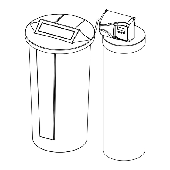
USA customers will need to add “-4” to the item numbers for ordering. CAUTION! This Softener should only be used for Municipal Water Supplies. How a WaterGroup Mixed Bed Water Softener Works Water softeners remove hardness in the water by exchanging particles in the water, or ions. They remove hard ions the calcium and magnesium in the water by trading it for sodium ions producing soft water. - Page 5 Familiarize Yourself with the Unit and Components Drain Line Connection to Valve Brine Line Control Valve Connection to Valve Brine Tube Safety Float/Air Distributor/Riser Brine Tank Check Inside Underbed Mineral/Resin Brine Well Media Bed Tank wrapped with Jacket...
-
Page 6: Installation Instructions
Check your water hardness. Use test strips (Part # 2793828-20) to get an estimation of water hardness and contact your lo- cal distributor to use WaterGroup laboratory for complete water analysis free of cost and no obligation to you. All government codes and regulations governing the installation of these devices must be observed. - Page 7 Preparations 1. Determine the best location for your water softener, Hard Electrical Panel Cold Soft Water Filtered bearing in mind the location of your water supply lines, Water drain line and 120 volt AC electrical outlet. Subjecting the Hard Soft Water Ground Strap softener to freezing or temperatures above 43°C (110°F) Electrical...
- Page 8 Softener The large funnel (sold separately part # 43000) makes filling the tank easier and neater. (Or an empty 1 gallon or 4 liter container with the bottom cut out Activated makes a good funnel.) Carbon (Black) Resin (Amber to Blonde) O-ring Support Bed...
-
Page 9: Installation Steps
The softener or filter is now charged with softening resin. g. It is recommended that the softener or filter tank now be completely filled with water (SLOWLY) to soak the resin or filtra- tion media before startup. This will allow the media to absorb water as well as help displace any trapped air. This will reduce the chance of backwashing resin or filter media out of the tank during the initial backwash on startup. - Page 10 Timer Controls Brine Line 3/8” Extra Cycle Button Outlet Inlet DOWN Drain 1/2” button UP button 2. Familiarize yourself with the location 3. Familiarize yourself with the buttons of the inlet, outlet and drain on the on the timer control. control valve.
- Page 11 5. Drain Line Connection: Using teflon tape, screw the 1/2” hose barb into Hose Barb the drain port in the valve. Attach 1/2” drain hose to the hose barb and tighten securely with a hose clamp. Run the drain line to a floor drain or a laundry drain.
- Page 12 Overflow Fitting outlet Drain Tubing intlet Secure hose in place Air Gap Drain 8. Make sure the bypass valve is in the 9. Plug the 24-volt transformer into a service position. 120 VAC 60 Hz outlet. Circuit Board Screen Position Label Brine...
-
Page 13: Water Conditioner Flow Diagrams
Water Conditioner Flow Diagrams Service Position Backwash Position Hard Water Soft Water Hard Water Soft Water Hard Water Hard Water Soft Water Soft Water To Drain To Drain To Drain To Drain Brine Rinse Position Slow Rinse Position Hard Water Soft Water Hard Water Soft Water... - Page 14 Rapid Rinse Position Brine Refill Position Hard Water Soft Water Hard Water Soft Water To Drain To Drain 13. Press once more to advance to the “4” Brine refill position. Wait until the water level reaches 6” in the brine tank. Water can be added to the tank to speed up the filling but the valve should be in the Brine Refill position for a minimum of two minutes to purge the air out of the injector set.
- Page 15 18. Put 40 kgs of crystal water softener 19. Set time of the day in the control salt in the brine tank. The unit will valve and program the user section of automatically fill the water to the the control. Refer to control valve pro- correct level when it regenerates.
-
Page 16: Programming Instructions
Programming Instructions Set Time of Day Press and hold buttons until display reads TD Adjust the displayed time with buttons. Press to resume normal operation Queuing a Regeneration 1. Press the button. The service icon will flash to indicate that a regeneration is queued. 2. -
Page 17: Diagnostic Programming Mode
Diagnostic Programming Mode Diagnostic Programming Mode Options Abbreviation Parameter Description Flow Rate Displays the current outlet flow rate Peak Flow Rate Displays the highest flow rate measured since the last regeneration Hours in Service Displays the total hours that the unit has been in service Volume Used Displays the total volume of water treated by the unit Displays the system’s reserve capacity calculated from the system... - Page 18 Controller Behavior Control Operation During Programming The control will only enter the Program Mode with the valve in Service. While in the Program Mode, the control will continue to operate normally, monitoring water usage and keeping all displays up to date. Control programming is stored in memory permanently, eliminating the need for battery back-up power.
-
Page 19: During Regeneration
During Regeneration Automatic Bypass The regeneration cycle lasts approximately 2 hours, after which soft water service will be restored. During regeneration, hard water is automatically bypassed for use in the household. Hot water should be used as little as possible during this time to prevent hard water from filling the water heater. -
Page 20: Maintenance Instructions
Maintenance Instructions Checking the Salt Level Check the salt level monthly. Remove the lid from the cabinet or brine tank, make sure salt level is always above the brine level NOTE: You should not be able to see water Adding Salt Use only clean salt labeled for water conditioner use, such as crystal, pellet, nugget, button or solar. - Page 21 Res-Up® Feeder Installation Instructions 1. Remove top cover, fill the Res-Up ® Feeder (plastic container) to the top with water so that the wick retaining clip, tube and wick are wetted, allow to soak for 15 minutes or more. Res-up feeder 5/8"...
-
Page 22: Before Servicing
Servicing 6200 Valve Before Servicing 1. Turn off water supply to conditioner : a. If the conditioner installation has a 3 valve bypass system first open the valve in the bypass line, then close the valves at the conditioner inlet & outlet. b. - Page 23 6200 Service Kits – Piston and Cartridge Assembly Dwg # Part # Part Description O-Ring 97 61799-01 Cartridge Assembly with Piston O-Ring 98 11335 Screw, 4-40X3/16 Blank 16394 O-Ring, 029 REVISIONS 13287 O-Ring, 123 ZONE REV. DESCRIPTION DATE APP'D Blank 61799 Seal and Spacer Cartridge 42920...
- Page 24 6200 Service Kits – Brine line Flow Control Kits Dwg # Part # Part Description 13302 O-Ring, 014 10141 O-Ring, 010 17307 Washer, Flow, 0.125 GPM 12094 Washer, Flow, 0.25 GPM 12095 Washer, Flow, 0.5 GPM 12097 Washer, Flow, 1.0 GPM 19334 Retainer, Flow Washer, BLFC 19335...
- Page 25 6200 Service Kits – Flow Meter Dwg # Part # Part Description 19791-01 Cable, Meter 19569 Clip, Flow Meter 13314 Screw, Slot Hex, 8-18 X0.6 19797 Meter, Assy,3 /4" Dual Port 13305 O-Ring, -119 14613 Flow Straightener 60626 Meter Only, Electronic Turbine 6200 Service Kits –...
- Page 26 6200 Service Kits – Circuit Board Dwg # Part # Part Description 19474-01 Harness, Power, SXT 19791-01 Cable Meter 42766-02 Circuit Board, SXT 17020 Screw 6200 Service Kits – Other Parts Dwg # Part # Part Description 17020 Screw, Stl Hex, 6-20 X 3/8 040050 Screw, Hex Washer 42919...
- Page 27 6200 Service Kits – Other Parts Continued Dwg # Part # Part Description 43052-01 Cover, Black 43052-02 Cover, Cream 10231 Screw, Slot Hex, 1/4-20 X 1/2 19597 Motor, 24V, 50/60 Hz 43053-01 Backplate, Black 43053-02 Backplate, Cream 19581 Bracket, Drive 10302 Insulator, Limit Switch 019688...
-
Page 28: 2310 Safety Brine Valve
Bypass Valve Assembly & Yokes (Plastic) Item No. Quantity Part No. Description 13305 O-ring, -119 13255 Clip, Mounting 13314 Screw, Hex Washer Head, 8-18 x 5/8 18706 Yoke, Plastic, 1” NPT 18706-02 Yoke, Plastic, 3/4” NPT 13708 Yoke, Brass, 3/4” NPT 13708NP Yoke, 3/4”... - Page 29 Servicing 6200 SXT Upflow Control Valve – Replacing Injectors and Screen 4. Apply silicone lubricant to the gasket and install Valve Body around oval extension on injector cap. 5. Apply silicone lubricant to Disperser two new o-rings and install Disperser...
- Page 30 Replacing Brine Valve Front Cover 1. Open the front cover of the powerhead, unscrew the brine cam and push the brine valve in order to remove the cam. 2. Remove the two screws from the grey brine valve bracket and remove it from the valve back plate. 3.
-
Page 31: Timer Replacement
Timer Replacement Meter Cable Screw Self tapping screw Screw Brine Valve Brine Cam Bracket 1. Disconnect the meter cable from 2. Open the front cover of the control 3. Remove the two screws from the the meter. valve, unscrew the brine cam and grey brine valve bracket and push the brine valve in order to remove it from the valve back plate. - Page 32 Piston Cartridge Assembly Replacement All 5 O-rings need to be inspected for damages REVISIONS ZONE REV. DESCRIPTION DATE APP'D and lubricated LAST SAVED IN SMARTEAM: DATE AND TIME CRITICALITY SYMBOLS PER QPSP-001.2 THE COMPONENT, PART, OR ASSEMBLY DESCRIBED IN THIS DOCUMENT MUST COMPLY WITH THE EU (EUROPEAN UNION) DIRECTIVE: RoHS DIRECTIVE 2002/95/EC, LEVEL I LEVEL II...
- Page 33 Servicing and Replacing Brine line Flow Control (BlFC) 1. Disconnect the brine line 2. Remove the BLFC assembly and pull 3. Remove the flow washer from the retainer clip. the flow washer retainer out of the retainer and clean it with water to BLFC housing with the help of plier.
-
Page 34: Circuit Board Replacement
Circuit Board Replacement Screws Meter Cable Power Harness 1. Detach the circuit board from valve 2. Disconnect the meter cable 3. Replace and connect the new front cover by removing two screws. and power head harness from the circuit board on the front cover. circuit board. - Page 35 6200 SXT Valve Dimensional Drawings All dimensions are in Inches (mm).
-
Page 36: Common Components
Parts Breakdown - Twin Tank Common Components Item No. Part No. Description 48004 Brine Well Cap 60626 Meter 60049 Bypass Resin Part Model Distributor Valve Tank Brine Tank Grid Safety Float Resin Number Description #21502 4932 MXC75 19495 6200306 19354 100283 13624 0.75 CF... -
Page 37: Error Codes
Error Codes Note: Error codes appear on the In Service display Error Code Probable Cause Recover and Resetting [Err 0] Drive motor is stalled Unplug the unit from the power source [Err 1] Drive motor is running continuously When power is restored to the unit, the Err _ display code clears. If the condition causing the error has not been resolved the Err _ code reappears in the four digit display. Do not attempt to troubleshoot this problem any further. [Err 2] There have been more than 99 days since Regeneration must occur for the unit to recover, the the last Regeneration. If the Day of the Week display to clear and the valve to mode of regeneration is selected and days function normally. since last regeneration exceeds 7 days. [ 7 - - 5 ]: To recover from [Err2], the user must [ 7 - - 5 ]: There have been more than 7 days initiate a regeneration or set at least one individual since the last regeneration. All individual day to 1. settings (d1, d2, d3, d4, d5, d6, d7) are set to [Err 3] Control board memory failure. Perform a Master Reset. If the error returns, do not attempt to troubleshoot this problem any further. Error Display Example NOTE: Unit will flash when an error exists. -
Page 38: Troubleshooting Guide
Trouble Shooting Guide Problem Possible Solutions 1. CONDITIONER DELIVERS HARD WATER A. Bypass valve is open B. No salt in brine tank A. Close bypass valve B. Add salt to brine tank and maintain salt level above water level C. Injector or screen plugged D. - Page 39 Trouble Shooting Guide Problem Possible Solutions 7. EXCESSIVE WATER IN BRINE TANK A. Plugged drain line flow control B. Brine valve failure A. Clean flow control C. Improper programming B. Replace brine valve C. Check programming and reset as needed 8.
-
Page 40: General Provisions
WaterGroup Guarantee WaterGroup Inc. guarantees that your new water conditioner is built of quality material and workmanship. When properly installed and maintained, it will give years of trouble free service. Seven Year Complete Parts Guarantee: WaterGroup Inc. will replace any part which fails within 60 months from date of manufacture, as indicated by the serial number provided the failure is due to a defect in material or workmanship. The only exception shall be when proof of purchase or installation is provided and then the warranty period shall be from the date thereof. Ten Year Guarantee on Mineral Tanks and Brine Tanks: WaterGroup Inc. will provide a replacement mineral tank or brine tank to any original equipment purchaser in possession of a tank that fails within 120 months, provided that the water conditioner is at all times operated in accordance with specifications and not subject to freezing. General Provisions: WaterGroup Inc. assumes no responsibility for consequential damage, labor or expense incurred as a result of a defect or for failure to meet the terms of these guarantees because of circumstances beyond its control. - Page 41 U.S. Headquarters WaterGroup Companies, Inc. 193 Osborne Road Fridley, MN 55432, USA 1-877-581-1833 TOLL FREE PHONE: Canada Headquarters WaterGroup Companies, Inc. 490 Pinebush Road, Unit 1 Cambridge, ON N1T 0A5, Canada 1-877-288-9888 TOLL FREE PHONE: www.watergroup.com Distribution locations Durham, NC...
Need help?
Do you have a question about the 6200 SXT and is the answer not in the manual?
Questions and answers