
Related Manuals for Roughneck 28804

Summary of Contents for Roughneck 28804
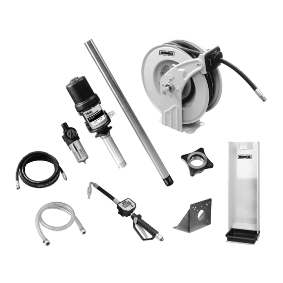
- Page 1 OIL TRANSFER KIT OWNER’S MANUAL WARNING: Read carefully and understand all INSTRUCTIONS before operating. Failure to follow the safety rules and other basic safety precautions may result in serious personal injury. Item # 28804...
-
Page 2: Technical Specifications
Thank you very much for choosing a Roughneck™ Product! For future reference, please complete the owner’s record below: Model: _______________ Purchase Date: _______________ Save the receipt, warranty and these instructions. It is important that you read the entire manual to become familiar with this product before you begin using it. -
Page 3: General Safety Regulations
GENERAL SAFETY REGULATIONS WARNING: Read and understand all instructions. WARNING: The warnings, cautions, and instructions discussed in this instruction manual cannot cover all possible conditions or situations that could occur. It must be understood by the operator that common sense and caution are factors that cannot be built into this product, but must be supplied by the operator. - Page 4 Do not misuse this equipment to pump fluids and solvents which may cause damage to the wetted parts of the equipment. Refer to instructions of the manufacturers of the fluids and solvents. Handle hoses carefully. Do not pull on hoses to move equipment. ...
-
Page 5: Installation
INSTALLATION Typical installation refers to Fig.1. Fig. 1 NOTE: The above typical installation is only for reference. It may be different from your actual system design. WARNING: If this is a new installation, or if the oil in the lines is contaminated, flush the lines before you install the kit. - Page 6 1. Ground Screw 2. Ground Wire Fig.1 Ground the pump Air and fluid hoses: Make sure they are effectively grounded. Air compressor: Follow the manufacturer's instruction to ground it. Control valve: Use proper grounding wire to connect it to the pump. Always keep the metal part of the control valve connected with the grounding equipment.
-
Page 7: Pressure Relief Procedure
Floor Mounting Wall Mounting Ceiling Mounting Fig. 2 3. INSTALLATION OF DROP TRAY Use one or two bolts and nuts (NOT INCLUDED) to secure the drop tray. 4. INSTALLATION OF CONTROL VALVE ①. Apply appropriate thread sealant around the male thread of flexible spout, and then screw the flexible spout to the meter. -
Page 8: Operation
④. Leave the drain valve open until you are ready to pressurize the system. (2) Clean the obstruction in the oil system, when any of the following cases occurs: ①. Problem on control valve, flexible hose, rigid tube or manual/auto tip. ②. -
Page 9: Operational Functions
Fig. 3 . Replace and tighten the nuts and washers. . Tighten the drive spring by turning the spool two or three circles and engage the latch pawl. Pull the hose through the roller opening in the guide arm and replace the stopper. 4. -
Page 10: Calibration Procedure
①. Move the flashing display to Zone ② by pressing “MENU”, then press “RESET” to choose measurement unit; ②. Press “MENU” over 3 seconds to exit the setting mode. B. Resetting the accumulated total Press “MENU” for 10 seconds, the accumulated total will be reset to be “0”. C. - Page 11 Exhausted fluid supply Refill and re-prime or flush Continuous air Assess wear or damage, and Worn or damaged air motor service air motor gasket or seal exhaust Exhausted fluid supply Refill and re-prime or flush Erratic pump Worn pump seals Replace pump seals operation Damaged hose...
-
Page 12: Maintenance
MAINTENANCE CAUTION: Remove all tension before servicing. Hazards or unsafe practices MAY result in minor personal injury, product or property damage. WARNING: Before performing any service, always disconnect and lock out compressed air or fluid, and remove all spring tension. Hazards or unsafe practices COULD result in severe personal injury or death. -
Page 13: Diagrams And Parts List
②. Store it out of the reach of children. ③. Always keep the pump at least 4 feet away from any heat source. DIAGRAMS AND PARTS LIST Part No. Description Qty. Part No. Description Qty. Oil pump Rigid suction hose Hose reel Pump adapter Oil Control Valve... - Page 14 1. 17130503 Oil pump Part No. Description Qty. Part No. Description Qty. Air motor cover Rope pin Spring piece O-ring Bracket Rope shaft Rope rocker Spring Shaft O-ring Copper ring Jar body Air control center Washer O-ring Steel wire Right silencer Adjustable screw U-seal Rubber gasket...
- Page 15 O-ring Bolt Oil inlet valve Bolt Piston shaft Adjustable nut Left silencer Transfer slipcover Bung adapter Shaft Label Screw O-ring O-ring Steel ball Piston Steel ball Wear parts Part No. Description Qty. Part No. Description Qty. Spring piece O-ring Copper ring O-ring O-ring Spring...
- Page 16 Bolt Spring core Bracket arm Spring Washer Drum Ratchet Swivel shaft Washer Washer Lock washer O-ring or seal Click pulley Washer Swivel shaft Lock washer Bearing cover Washer Ball bearing Shaft Bearing washer Washer Guide sub-plate Lock washer Drum Bracket arm Roller axle Double bolt Roller...
-
Page 17: Warranty
1-5* O-ring 3-9* O-ring Screw 3-10 Seat 1-7* Washer, flat 3-11 Battery cover 3-12 Spring 3-13* Battery 1-10* Seat 3-14 Screw 1-11 Washer 3-15 Shaft 1-12 Spring 3-16 Oval Gear 1-13* Filter 3-17 Magnetic Rod Adapter 3-18 Bolt 3-1* O-ring 3-19* Waterproof protector Meter Holder...
Need help?
Do you have a question about the 28804 and is the answer not in the manual?
Questions and answers