
Related Manuals for Sun Microsystems StorageTek SL24


Summary of Contents for Sun Microsystems StorageTek SL24
- Page 1 Sun StorageTek™ SL24 Tape Autoloader and SL48 Tape Library User and service guide AH945-96001 Part number: AH945–96001 First edition: July 2007...
- Page 2 Nothing herein should be construed as constituting an additional warranty. Sun StorageTek™ SL24 Tape Autoloader and Sun StorageTek™ SL48 Tape Library are trademarks of Sun Microsystems, Inc. Other trademarks may be mentioned herein which belong to other companies.
-
Page 3: Table Of Contents
Contents About this guide ......Intended audience ........Document conventions and symbols . - Page 4 Magazines ......... 4 Operating the Autoloader or Library .
- Page 5 Configuring automatic cleaning ......Restoring factory defaults ......Operations .
- Page 6 Performance problems ........Average file size ........File system type .
- Page 7 Class A equipment ....... . Class B equipment ....... . . Declaration of conformity for products marked with the FCC logo, United States only .
- Page 8 Figures 1 ..SL24 default SCSI IDs ......2 ..SL48 default SCSI IDs .
- Page 9 38 ..Status: Drive page (parallel SCSI) ......39 ..Status: Drive page (Fibre Channel) ......40 ..Status: Inventory page .
- Page 10 79 ..Removable Storage service ......1 19 80 ..Access holes for the right and left magazines .
- Page 11 Tables 1 ..Document conventions ......2 ..Autoloader and Library capacity ......3 ..LTO-2 HH Autoloader and Library specifications .
-
Page 13: About This Guide
About this guide This guide provides information about: • Installing a Sun StorageTek™ SL24 Tape Autoloader or SL48 Tape Library • Configuring and operating a Sun StorageTek™ SL24 Tape Autoloader or SL48 Tape Library • Troubleshooting a Sun StorageTek™ SL24 Tape Autoloader or SL48 Tape Library •... -
Page 14: Rack Stability
NOTE: Provides additional information. TIP: Provides helpful hints and shortcuts. Rack stability Racks must be stable to insure the safety of personnel and avoid equipment damage. WARNING! To reduce the risk of personal injury or damage to equipment: • Extend leveling jacks to the floor. •... -
Page 15: Features And Overview
1 Features and overview The Sun StorageTek™ SL24 Tape Autoloader and SL48 Tape Library provide compact, high‐capacity, low‐cost solutions for simple, unattended data backup. This unique design houses up to 12 tape cartridges for each U of height, with easy access to tape cartridges via removable magazines and one or more mailslots (see Table 2). -
Page 16: Interface Specifications And Requirements For Parallel Scsi Drives
Table 4 LTO‐3 FH Autoloader and Library specifications Characteristic Specification Tape drive LTO-3, full-height, parallel SCSI and FC Maximum data transfer rate — one drive Native: 80 MB/s (288 GB/hr.) Compressed (2:1): 160 MB/s (576 GB/hr.) Maximum data transfer rate — two drives Native: 160 MB/s (576 GB/hr.) Compressed (2:1): 320 MB/s (1 152 GB/hr.) Interface specifications and requirements for parallel SCSI... -
Page 17: Default Scsi Ids
RAID controllers, and most on‐board HBAs do not support multiple LUNs. IMPORTANT: The Autoloader or Library requires an HBA that supports multiple LUNs, which is also called “LUN scanning.” Default SCSI IDs The default SCSI ID for parallel SCSI tape drives is managed by the Autoloader or Library. The default SCSI ID for all full‐height tape drives is 4. -
Page 18: Front Panel Overview
If you plan to connect the Autoloader or Library directly to the server, you will need a 2 Gb or 4 Gb Fibre Channel HBA. A 4 Gb HBA is suitable for all supported drive types. A 1 or 2 Gb HBA might result in performance degradation when backing up highly compressible data to a 4 Gb tape drive. -
Page 19: Back Panel Overview
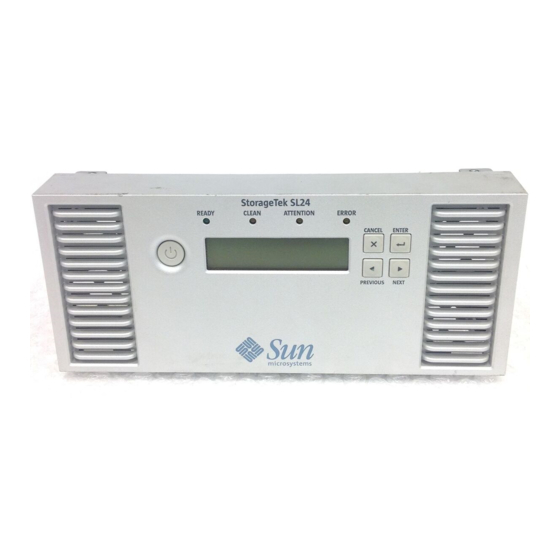
11256 Figure 5 Operator control panel LEDs Green Ready. Illuminated when power is on. Blinking when there is tape drive or robotics activity. Amber Clean. Illuminated when the tape drive has determined that a cleaning cartridge should be used. Cleaning is only necessary when the device directs you to do so. Additional cleaning is not necessary. -
Page 20: Tape Drive Led
11362 Figure 7 SL24 with a Fibre Channel drive 2. Fan 1. Fibre Channel ports 3. Power connector 4. Tape drive 5. Ethernet port 6. Serial port (Factory use only) 7. USB port 8. Magazine release hole 9. Pull-out tab containing the serial number and other product information The device requires a 110/220 volt AC power connection. -
Page 21: Installing The Autoloader Or Library
2 Installing the Autoloader or Library This chapter contains the information you need to install and configure your Autoloader or Library. The installation steps are: • Preparing the host • Planning the SCSI configuration Planning the Fibre Channel configuration • Choosing a location •... -
Page 22: About Parallel Scsi Busses
If the host computer will have multiple parallel SCSI devices, you must decide how they will be configured into one or more parallel SCSI busses. About parallel SCSI busses A parallel SCSI bus consists of the host bus adapter (HBA), the parallel SCSI devices, the parallel SCSI cables, and the terminators. -
Page 23: Planning The Fibre Channel Configuration
11434 Figure 10 SL24 parallel SCSI tape drive default SCSI addresses 1. Tape drive with SCSI address 4 2. Tape drive with SCSI address 5 SL48: For full‐height tape drives the default SCSI address is 4. For half‐height drives, the default •... -
Page 24: San Connection
SAN connection All switches between the host and the Autoloader or Library must be of the appropriate type. A 1 or 2 Gb switch in the path may result in performance degradation when backing up highly compressible data to a 4 Gb tape drive. Configure zoning on the Fibre switch so only the backup servers may access the Library. -
Page 25: Unpacking The Autoloader Or Library
Table 6 Location criteria Criteria Definition Tabletop The Autoloader or Library can only be placed on a flat surface if it is installed in requirements the optional tabletop conversion cover. Select a location that is flat, sturdy, and close to the host server. Ensure that all of the plastic feet on the tabletop conversion cover will be supported. -
Page 26: Identifying Product Components
CAUTION: Do not place the Autoloader or Library on either end or its sides as this may damage it. Remove any other accessories from the shipping container. Save the packaging materials for future use. Identifying product components Table 7 Product contents SL24 Tape Autoloader SL48 Tape Library 11358... -
Page 27: Removing The Shipping Lock
Removing the shipping lock The shipping lock prevents the robotic transport mechanism from moving during shipment. You must remove the shipping lock before powering on the device. The shipping lock is held in place with a piece of tape and is located in the top center of the device. After the shipping lock is removed, it should be stored on the back panel of the device for future use. -
Page 28: Rack Kit
WARNING! The SL24 Tape Autoloader weighs up to 15.6 kg (34.3 lb) without media and up to 20.4 kg (44.9 lb) with media (24 cartridges). The SL48 Tape Library weighs up to 24.6 kg (54.1 lb) without media and up to 34.2 kg (75.2 lb) with media (48 cartridges). -
Page 29: Replacing Alignment Pins
11421 Figure 15 Replacing alignment pins 11422 Figure 16 Attaching the clip nut to the rail Using two screws with washers from the Standard rack hardware packet and a #3 Phillips screwdriver, secure the front of one rail to the front of the rack, as shown in Figure 17. -
Page 30: Securing The Rails To The Rack
11423 Figure 17 Securing the rails to the rack Skip this step if you are installing an SL24 Autoloader or installing an SL48 Library into a rack with 10–32 threaded holes in the rack column. Racks having vertical mounting rails with M6 threaded holes in the rack column (Sun Rack 900 and 1000): On the front of the rack, install one clip nut from the Standard rack hardware packet on each side in the location shown in Figure... -
Page 31: Installing The Tabletop Conversion Kit
11344 Figure 19 Securing the Tape Autoloader or Library to the rack Installing the Tabletop Conversion Kit The Rack to Tabletop Conversion Kit supports the edges of the Autoloader or Library, but is not a structural top. IMPORTANT: You may not place any weight on top of the Autoloader or Library, even with the cover installed. To install the cover: Place the cover on a flat, level surface behind the device. -
Page 32: Installing A Redundant Power Supply
• SL24: The Autoloader should have a tape drive in the bottom bay. Install the additional tape drive in the top bay. • SL48: Install the tape drive in drive bay directly above the existing tape drives. If you leave a space and later add a drive in the space, the new drive will be assigned the next higher drive number, leaving the drives numbered out of order. -
Page 33: Changing The Scsi Address (Parallel Scsi Drives Only)
11395 Figure 22 Installing the new power supply Tighten the blue thumbscrews by hand to secure the power supply to the chassis as shown in Figure 11263 Figure 23 Redundant power supply thumbscrews Changing the SCSI address (parallel SCSI drives only) The pre‐configured SCSI address for all full‐height tape drives is 4. -
Page 34: Connecting The Fibre Channel Cables (Fibre Channel Devices Only)
Attach one end of the parallel SCSI cable (included in the accessory package) to one of the connectors on the back panel of the tape drive (see Figure 24). 10777 Figure 24 Attaching the parallel SCSI cable to the tape drive Attach the other end of the parallel SCSI cable to the connector on the parallel SCSI host bus adapter or to the connector on the previous device on the parallel SCSI bus. -
Page 35: Powering On The Autoloader Or Library
Powering on the Autoloader or Library WARNING! This product can only be used with a Sun‐approved power cord for your specific geographic region. Use of an non‐Sun‐approved power cord may result in: 1) not meeting individual country specific safety requirements; 2) insufficient conductor ampacity that could result in overheating with potential personal injury and/or property damage;... -
Page 36: Verifying The Connection
Configure the network settings. Configuring the networking enables you to monitor, configure, and control most Autoloader or Library functions from the RMI. The device can either get an IP address from a DHCP server or you can set a static IP address. -
Page 37: Tape Cartridges And Magazines
3 Tape cartridges and magazines This chapter explains which media to use with your Autoloader or Library, and how to label and write‐protect your tape cartridges. Careful labeling and handling of the tape cartridges will prolong the life of the tape cartridges and the Autoloader or Library. Tape cartridges Use the Ultrium data and cleaning tape cartridges designed for your model of Autoloader or Library. -
Page 38: Labeling Tape Cartridges
Labeling tape cartridges The device contains a bar code reader that reads the tape labels and stores the inventory data in memory. The device then provides the inventory information to the host application, OCP, and RMI. Having a bar code label on each tape cartridge enables the bar code reader to identify the cartridge quickly, thereby speeding up inventory time. -
Page 39: Backward Read Compatibility
Slide the switch to the right to write‐protect the cartridge. An indicator, such as a red mark or • small padlock, is visible showing that the cartridge is write‐protected (see Figure 27, 2). 10454 Figure 27 Write‐protecting the data cartridge 1. -
Page 40: Sl24 Slot Numbering With The Single Mailslot Enabled
Mailsl o t 1 0 7 7 1 Figure 28 SL24 slot numbering with the single mailslot enabled * When the mailslot is disabled, the mailslot becomes Slot 1 and all other slots are re‐numbered accordingly. Tape cartridges and magazines... -
Page 41: Sl48 Slot Numbering With Mailslot Disabled
On the SL48, the storage slots are numbered starting with the of the lower‐left magazine, as shown in Figure 11387 Figure 29 SL48 slot numbering with mailslot disabled When the SL48 mailslot is enabled, all of the storage slot numbers are adjusted, as shown in Figure The storage slots in the other magazines are renumbered accordingly. - Page 42 Tape cartridges and magazines...
-
Page 43: Operating The Autoloader Or Library
4 Operating the Autoloader or Library The Autoloader or Library can be operated by the following methods: Remote management interface (RMI) — this interface lets you monitor and control the • Autoloader or Library from a web page. You can access most Autoloader or Library functions from the RMI. -
Page 44: Login
• “Setting error log mode” on page 59 • “Setting event notification parameters” on page 60 • “Restoring factory defaults” on page 60 • “Operations” on page 62 • “Moving media” on page 62 • “Updating the current media inventory” on page 62 •... -
Page 45: Status Pane
TIP: By default, the administrator password is unset; all of the digits are null. You must set the administrator password from the OCP to protect the administrator functions on the OCP and enable the administrator functions in the RMI. Status pane The System Status pane (see Figure 32) shows the current device and drive status. -
Page 46: Getting Help
• Removed. A power supply was installed in this location before but has been removed. Power Supply 1 will always show Removed when it is missing. Power Supply 2 will show Removed until the Library is rebooted. Getting help For additional information about fields on the RMI screens, click on Help in the upper right corner (see Figure 33). -
Page 47: Viewing Static Drive Information
• Automatic — the device will switch from Sequential to Random mode if it receives media changer SCSI commands. • Manual — the device will stay in the current mode until another mode is configured by a user. • Random — the device will not automatically load and unload tapes. Instead, it will wait for commands from the backup software or the OCP to load and unload tapes. -
Page 48: Identity: Drive Page (Parallel Scsi)
Figure 35 Identity: Drive page (parallel SCSI) Operating the Autoloader or Library... -
Page 49: Identity: Drive Page (Fibre Channel)
Figure 36 Identity: Drive page (Fibre Channel) You can see, but not modify, the following: • Vendor ID — will always be HP. • Product ID — product identification information that is given by the drive. • Serial Number — electronic serial number of the drive. It should match the physical serial number of the drive. -
Page 50: Status
Status Viewing dynamic device information displays dynamic information about the device. When you click Refresh, the Status: Library page status is updated immediately. Figure 37 Status: Library or Autoloader page You can see, but not modify, the following: • Status — the overall status of the device The device is operating normally. -
Page 51: Viewing Dynamic Drive Information
example, Level 1. Left Magazine is the bottom magazine on the left side looking at the Library from the front. (SL48) • Right Magazine — Present, if the device senses the presence of the right magazine. (SL24) • Level n. Right Magazine — Present, if the Library senses the presence of the right magazine at level n. -
Page 52: Viewing The Tape Cartridge Inventory
Figure 39 Status: Drive page (Fibre Channel) You can see, but not modify, the following: • Status of the drive The drive is operating normally. The device is functional, but might have an issue that should be addressed. The drive is in a failed state. •... -
Page 53: Status: Inventory Page
Figure 40 Status: Inventory page A dark rectangle indicates a full slot, a yellow rectangle indicates a cartridge with a problem, and a white rectangle indicates an empty slot. To get detailed information about the tapes in a magazine, click on the + button to expand the display for the magazine (see Figure 41). -
Page 54: Configuration
Figure 41 Status: Inventory: Media details pane In the media details pane, • Slot # — lists “Mailslot” or the index number of each slot in the magazine from lowest to highest. • Attn — indicates an attention state for storage slots or provides information on the mailslot state. - Page 55 Figure 42 Configuration: System page A list of changes that can be made are: • Autoloader or Library Name — used as the sender of e‐mail alerts and the identity of the device in SNMP messages. The name may not include spaces or special characters. •...
-
Page 56: Changing The Drive Configuration
CAUTION: Use caution when choosing Loop mode because it makes it possible to overwrite data on previously written cartridges. Automatic mode: The default setting is Automatic mode, which allows the device to switch between Random and Sequential modes depending on the SCSI commands received. The device stays in Sequential mode until it receives media changer SCSI commands which put it in to Random mode. - Page 57 Figure 43 Configuration: Drive page (parallel SCSI) For each parallel SCSI drive, you may change the • SCSI ID — the SCSI address for a parallel SCSI tape drive. • Power On — power the tape drive on or off. Figure 44 Configuration: Drive page (Fibre Channel) For a Fibre Channel tape drive, you can use this screen to configure the FC ports.
-
Page 58: Changing The Network Configuration
Changing the network configuration Use the Configuration: Network page to see and modify the current network configuration. When you request a change, a pop‐up box will ask you to confirm the changes. From this page you can enable and configure SNMP (Simple Network Management Protocol). The device supports both SNMP configuration and SNMP traps. -
Page 59: Setting The Date And Time
NOTE: You must set the administrator password with the OCP before you can access administrator functionality in the RMI. For SL24, see “Changing the administrator password” on page 75. For SL48, see “Changing the administrator password (Configuration > Administrator Password)” on page 99. Figure 46 Configuration: Password page The password is exactly eight numbers, each between 0 and 9. -
Page 60: Setting Event Notification Parameters
Figure 48 Configuration: Log page Setting event notification parameters Configuration: Event notification page lets you configure e‐mail notification of Autoloader or Library events. Figure 49 Configuration: Event notification page You may change the: • Notification Level — the types of events for which the device should send e‐mail •... - Page 61 IMPORTANT: Once you reset the administrator password to null, you will not be able to access the administrator functions in the RMI until you set an administrator password through the OCP. To change the administrator password, “Configuration: Password page” on page 59. Figure 50 Configuration: Restore defaults page The restored settings are: •...
-
Page 62: Operations
Operations Moving media Use the Operations: Move Media page to move tape cartridges within the device. IMPORTANT: Moving media manually can interfere with backup software operations. Ensure backups are complete before moving media. Figure 51 Operations: Move Media page To move a tape, select the source and destination and then click the Move button in the center of the screen to start the move. -
Page 63: Releasing And Replacing The Magazines
Figure 52 Operations: Inventory page Releasing and replacing the magazines to release the right or left magazine. When you click Release, the Use the Operations: Magazine page device will unlock the magazine and display Left Magazine Unlocked or Right Magazine Unlocked on the OCP screen. -
Page 64: Service The Library - Service Restricted
Figure 54 Support: General Diagnostic page Service the Library ‐ Service restricted Support: Service the Library page page can only be accessed by service personnel to execute detailed tests on the different components of the device or special read/write diagnostics on the drives. Figure 55 Support: Service the Library page Determining and updating firmware Use the... -
Page 65: Rebooting The Device
Figure 56 Support: Firmware page Rebooting the device Use the Support: Reboot page to do a soft reset of the device, which will run the Power On Self Test (POST) and scan for a new inventory. The RMI web page will refresh itself after a short time delay. This time should be sufficient to reload the page. -
Page 66: Cleaning Tape Drives
Figure 58 Support: Library Logs page Cleaning tape drives Use the Support: Clean Drive page to clean the tape drives. • Slot # — select the slot number of the cleaning tape • Drive — select the drive to be cleaned Figure 59 Support: Clean Drive page Sun Service link Use the... -
Page 67: Led Indicators
• “Inventory” on page 72 • “Device information” on page 73 • “Drive information” on page 73 • “Component status” on page 74 • “Network information” on page 74 • “Configuration” on page 74 • “Changing the administrator password” on page 75 •... -
Page 68: Autoloader Home Screen
11159 Figure 61 LEDs Green Ready. Illuminated when power is on. Blinking during tape drive or robotics activity. Amber Clean. Illuminated when a cleaning cartridge should be used. Amber Attention. Illuminated if the device has detected a condition that requires attention. Amber Error. -
Page 69: Operator Control Panel Buttons
Operator control panel buttons The four operator control panel buttons, described in Figure 62, let you traverse the OCP menu structure and enter information. 10763 Figure 62 Operator control panel buttons Cancel Cancels the current menu option, returns to the previous menu level, or returns to the Home screen. -
Page 70: Entering The Administrator Password
HOME Unlock Mailslot Status/Information Configuration Operations Support Change Admin Inventory Unlock Left Magazine Power On/Off Drives Mailslot Unlocked Password Once sensors detect Set Reserved Autoloader Information Unlock Right Magazine Run Demo Slot Count Mailslot is open Drive 1 Information Configure Mailslot Clean Drive Run Slot T o Slot Test... -
Page 71: Unlocking The Mailslot
Press Enter. The number you selected is replaced with an asterisk (*), and the cursor proceeds to the next text box. Repeat steps 1 and 2 until you have entered all eight numbers. After the last number has been entered, the screen continues to the restricted area. NOTE: If you forget the administrator password, you cannot enter a new password. -
Page 72: Inventory
Inventory This option provides information on which slots have cartridges and which are empty. The second line on the screen displays one of: • Full (tapes without bar code labels) • Bar code identification from the tape • Empty The device has the following inventory locations: •... -
Page 73: Autoloader Information
Select Left or Right Magazine. The OCP will display the contents of the lowest numbered slot in the magazine. The display will show the tape bar code number, Full, or Empty. Use Previous or Next to scroll through the remaining slots in the magazine. Press Cancel to choose another inventory location. -
Page 74: Component Status
Component status To obtain component status: From the Home screen, press Previous or Next until the screen displays Status/Information. Press Enter to select. Press Previous or Next until the screen displays Component Status. Press Enter to select. By using Previous or Next, you can select from the following information screens: •... -
Page 75: Changing The Administrator Password
From the Home screen, press Previous or Next until the screen displays Configuration. Press Enter to select. Press Previous or Next until the screen displays your selected function. Press Enter to select. Changing the administrator password Use Change Admin Password to set or change the administrator password. Once the administrator password is set, you must know the administrator password or the service password to change the administrator password. -
Page 76: Bar Code Report Format
From the Home screen, press Previous or Next until the screen displays Configuration. Press Enter to select. Press Previous or Next until the screen displays Configure Mailslot. Press Enter to select. Enter the administrator password if prompted. The screen displays either Mailslot Enabled or Mailslot Disabled. Press Previous or Next until the screen displays Disable Mailslot? or Enable Mailslot?. -
Page 77: Setting The Master Drive
NOTE: Sun recommends that you cable Port A only and that you configure Port B for Auto Detect on Fibre Speed and Port Type. To configure the FC settings: From the Home screen, press Previous or Next until the screen displays Configuration. Press Enter to select. - Page 78 you can also change the mode from the Configuration menu. Choose the operating mode based on the capabilities of the software controlling the tape cartridges. Access to this feature requires the administrator password. Automatic mode The default setting is Automatic mode, which allows the device to switch between Random and Sequential modes depending on the SCSI command received.
-
Page 79: Setting The Date And Time
Press Previous or Next until the screen displays either Loop Mode Disabled or Loop Mode Enabled. To change loop mode, press Enter. The screen displays either Enable Loop Mode or Disable Loop Mode. Press Enter to select the loop mode. Setting the date and time NOTE: When setting the hours, the time is based on a 24‐hour clock. -
Page 80: Configuring Automatic Cleaning
Press Previous or Next until the screen displays Gateway Address. To change the Gateway Address, press Enter. The screen displays Set Gateway Address, with the first number flashing. Press Previous or Next to change the flashing number to the correct value. Press Enter to select the next number. -
Page 81: Operations
• E‐mail notification: disabled, but configurations retained The following settings are not reset: • Administrator password • Network settings (network is always enabled) • Date and time To restore the factory defaults: From the Home screen, press Previous or Next until the screen displays Configuration. Press Enter to select. -
Page 82: Moving Tapes In The Autoloader
http://www.sun.com/storagetek/tape_storage/tape_media/lto/.Use only Ultrium Universal cleaning cartridges. IMPORTANT: If the cleaning cartridge is not a valid cleaning cartridge, the LCD screen displays Invalid Tape and the cartridge is returned to its original location. IMPORTANT: If the Clean drive LED or the Media Attention LED (on load or unload) occurs when inserting the same cartridge after you have cleaned the drive, there may be a problem with that cartridge. -
Page 83: Updating Tape Cartridge Inventory
Enter the administrator password if prompted. Use Previous or Next to select from the possible sources: • Mailslot • Right Magazine • Left Magazine • Drive 1 • Drive 2 (if two drives are present) When the correct source is displayed, press Enter to select. If the source selected is a magazine, use Previous or Next to select the slot (the same applies for the Right Magazine). -
Page 84: Enabling Password Locks
CAUTION: This option interrupts the current backup or restore operation and causes the operation to fail. Use this option if the device is in an error state. To reboot: From the Home screen, press Previous or Next until the screen displays Operations. Press Enter to select. -
Page 85: Running The Demonstration
Running the demonstration Use this option to run a device demonstration program. The demonstration continues until the Cancel button is pressed on the operator control panel. Access to this feature requires the administrator password. To run the demonstration: From the Home screen, press Previous or Next until the screen displays Support. Press Enter to select. -
Page 86: Upgrading Firmware
Press Previous or Next until the screen displays Select Cycles. Use Previous or Next to select a number. Press Enter. While the test is running, the screen displays progress as shown: Wellness test. The second line on the display shows the number of loops completed. When the test is complete, the screen displays either Test Passed or an error code. -
Page 87: Viewing Logs
Press Previous or Next until the screen displays the filename of the drive firmware file on the USB drive. Press Enter to select the firmware file. If the upgrade failed, press Enter to display the error code and message describing the cause of the failure. -
Page 88: Sl48 Operator Control Panel
Press Previous or Next until the screen displays Drive 1 or Drive 2. The second line on the display shows the bar code number of the tape or state Full. Press Enter to select the desired drive to eject the tape. If the tape is successfully ejected from the drive, the screen displays the slot location where the tape was moved to. -
Page 89: Operator Control Panel Navigation Buttons
• Force ejecting a drive (Support > Force Drive Eject) • Rebooting the tape library (Support > Reboot) Operator control panel navigation buttons Four menus are accessed through the operator control panel: Info, Configuration, Operations and Support. Use the navigation buttons to select menu items and work with the screen displays. The navigation buttons have different functions depending upon where you are in the menu structure (see Table 11... -
Page 90: Using The Ocp
Using the OCP Each time the Tape Library is powered on or rebooted, or after five minutes of inactivity, a splash screen is briefly displayed, after which the OCP menu is displayed, showing current system status information. You will be required to enter the administrator password for all functions that are password‐protected. Figure 65 OCP menu, showing initial system status information The OCP menu includes a status message bar, menu bar, and display area. -
Page 91: Administrator Password
HOME Info C o n f i gu r at i o n Op e r at i o n s S u pp o r t Status P o w e r On/Off D r i v e s Library Open Mailslot(s) Unlock... -
Page 92: Illustrated Menu Option And Navigation Examples
All other Configuration, Operations, and Support options are locked. After five minutes of inactivity, the OCP returns to the splash screen. To access password‐protected tasks, you must reenter the administrator password. The administrator password is originally null. Sun strongly recommends that you assign a password during the installation process, see Changing the administrator password (Configuration >... -
Page 93: Operations Menu
NOTE: If you exchange the magazine in the lower‐left position with one that has different mailslot capabilities, a warning appears telling you that the mailslot type is incompatible with the configuration. To access the mailslots do the following: Highlight Operations -> Open Mailslots and press OK to select it. Figure 68 Operations menu The mailslot located in the lower left magazine ejects automatically. -
Page 94: Moving Media (Operations > Move Media)
NOTE: If the SCSI Prevent/Allow Media Removal bit is set, the mailslot cannot be unlocked/opened from the front panel and the following message is displayed: “Media Removal Prevented by Host Software”. Press OK to continue and return to the open mailslot pull‐down menu. Try the operation again from the backup software. -
Page 95: Info Menu
If appropriate, move to the Source field and repeat step 4 to specify the source cartridge. Use the Up and Down arrows to move to the Destination Type field and press OK. Use the Up and Down arrows to change the value of the highlighted field. When the highlighted field shows the desired value, press OK to select. -
Page 96: Viewing Identity Information (Info > Identity)
For Fibre Channel drives, the following additional items are displayed: • The link status of each port may be: No Light, Logged In, Logged Out, ALPA Conflict, or Negotiation Link. No Light or ALPA Conflict indicates an error condition. See “Fibre Channel connection problems”... -
Page 97: Configuration Menu
Configuration menu The Configuration menu provides the following options: Figure 72 Configuration menu Changing the Library configuration (Configuration > Library Configuration) This option allows you to specify the drive that is assigned as master drive and the Library mode, and define how many slots are active and whether the mailslots are enabled. -
Page 98: Changing The Drive Configuration (Configuration > Drive Configuration)
Sequential or Random mode. If you do this, it remains in Sequential or Random mode until you revert to Automatic, which can be accessed through the Configuration menu. Random mode Random mode is used when there is a full featured or a robotics aware backup application in use. This is the most common mode of operation. -
Page 99: Changing The Network Configuration (Configuration > Network Configuration)
CAUTION: If you change the SCSI ID, you must also cycle power on the host server and reconfigure the backup software before using the Library. Fibre Channel drives: This option allows you to configure the Fibre Speed, Type, ALPA, and Loop mode for the driveʹs Fibre Channel ports. -
Page 100: Setting The Library Date And Time (Configuration > Set Date/Time)
11435 Figure 73 SL48 parallel SCSI tape drive default SCSI addresses 1. Tape drives with SCSI address 4 2. Tape drives with SCSI address 5 The Library will no longer recall drives that have been removed. • Master drive: reset to Drive 1 or the lowest numbered existing drive •... -
Page 101: Operations Menu
Operations menu The Operations menu contains the following Library operation options: Figure 74 Operations menu Opening the mailslot (Operations > Open Mailslot) The mailslots are used only with host system software that supports this feature. The mailslot feature allows you to insert or remove up to three tapes. Left magazines are available without mailslots, with one mailslot, or with three mailslots. -
Page 102: Moving Media (Operations > Move Media)
Once all left or right magazines are correctly installed, the Library inventories the magazines. NOTE: Due to the Library design, all left or all right magazines will be unlocked. The Library will halt robotic functions until all magazines are present. It is not possible to unlock all of the magazines at once from the front panel. -
Page 103: Powering Drives On And Off (Support > Power On/Off Drives)
Figure 76 Support menu Powering drives on and off (Support > Power on/off Drives) This option allows the powering up or down of a drive without interrupting power to the rest of the Library and the other drives. This is typically used when replacing one drive. Access to this feature requires the administrator password. -
Page 104: Running Tests (Support > Run Tests)
Running tests (Support > Run Tests) This option allows you to run a demo, a wellness test or a slot to slot test and to specify the number of test cycles required. You can abort the test at any time, if required. Access to this feature requires the administrator password. -
Page 105: Force Ejecting A Drive (Support > Force Drive Eject)
Force ejecting a drive (Support > Force Drive Eject) This option attempts to force the tape drive to eject the tape and place it into an open slot in the Library. Access to this feature requires the administrator password. Before issuing this command, Sun recommends that you attempt to eject the tape using the backup software and move command on the operator control panel. - Page 106 Operating the Autoloader or Library...
-
Page 107: Troubleshooting
5 Troubleshooting CAUTION: This Library or Autoloader is designed to operate when installed in a rack using the included rack rails. The Library and Autoloader can also be set on a flat surface when mounted in the optional Rack‐to‐Tabletop Conversion Kit. Operating the Library or Autoloader without one of these kits, such as on a flat surface without the Rack‐to‐Tabletop Conversion Kit, could result in device errors. -
Page 108: Sl48 Parallel Scsi Tape Drive Default Scsi Addresses
• SL48: For full‐height tape drives the default SCSI address is 4. For half‐height drives, the default SCSI address for the bottom drive in each full‐height drive bay is 4 and the default SCSI address for the top drive is 5 as shown in Figure 11435 Figure 78 SL48 parallel SCSI tape drive default SCSI addresses... -
Page 109: Fibre Channel Connection Problems
detects the host adapter. Make sure that the proper device driver is installed for the parallel SCSI host adapter. • If the Autoloader or Library is detected by the operating system, but not by the application software: • Refer to the documentation included with your backup application for instructions on how to verify proper installation. -
Page 110: Operation Problems
• The speed is probably set incorrectly. Try setting the speed to Automatic (on the RMI interface) or Auto Detect (on the OCP). • If there are still issues, change the port type to Auto Detect. If the screen shows No Light: •... -
Page 111: Failure/Attention Indications Displayed On The Front Panel
Table 15 Failure/attention indications displayed on the front panel Problem Solution “!” in operator panel inventory Export the data cartridge marked with an ! in the inventory. display. The cartridge is either damaged, incompatible with the drive, or the wrong type for the attempted operation. For the SL24, see “Operator control panel (OCP)”... -
Page 112: Media Problems
Table 17 Media problems Problem Solution Cleaning or data cartridge Make sure you are using data and cleaning cartridges that incompatible with drive. are compatible with the drive and model of your device (see “Tape cartridges” on page 37) and that you are using the correct cartridge type for the operation. -
Page 113: Parallel Scsi Device Not Detected
Table 18 Parallel SCSI device not detected Problem Solution • Check that the HBA supports multiple LUNs and this feature is Device not detected enabled. If not, only the tape drive will be detected. Check for conflicting SCSI IDs. • •... - Page 114 Table 19 Attention LED is lit Problem Solution Both the Attention and Cleaning This is most likely caused by a dirty drive that cannot read a tape and LEDs are lit. marks the tape invalid. View the inventory with the RMI. Note the slots that have tapes marked with !.
-
Page 115: Performance Problems
Table 20 Inventory problems Problem Solution • Verify that the label is properly applied. See The inventory labels the cartridge “Labeling and loading the tape cartridges” on page 36. Full instead of showing its bar code • Verify that the label is not soiled. The inventory process takes a long Apply high-quality labels to all tape cartridges. -
Page 116: Average File Size
• “Operating system configuration” on page 119 • “Backup server” on page 120 • “Backup type” on page 120 • “Connection from the host server to the device” on page 121 • “Media” on page 122 Average file size The hard drive must seek to the position of a file before it can start reading. The more time the disks are seeking to files, the lower the performance. -
Page 117: Connection From The Host Server To The Disks
Table 24 Performance impact of various file systems File system Performance impact Recommendations None. Disk array GOOD. Disk arrays typically provide excellent access to data. They usually include many disks, which improves bandwidth. Server or workstation VARIABLE. RAID uses a group of To improve performance on a disk system, with RAID disks to improve performance, and... - Page 118 Connection type Performance impact Recommendations Fibre: 4 GB GOOD. When fully used, a 4 GB fibre connection can provide enough bandwidth for the following number of tape drives: • LTO-2 HH: 8 • LTO-3 FH: 2 • LTO-2 HH: GOOD. When fully used and Parallel SCSI: Ultra If cables not designed for Ultra assuming that the connection to the disks does...
-
Page 119: Operating System Configuration
Operating system configuration The operating system configuration and other programs running on the host computer can impact the ability of the host computer to transfer files from the disks to the tape drive. Windows To improve backup performance and improve SAN stability, shutdown and disable the Windows Removable Storage Manager unless the backup software requires it: From the Windows start menu, select Control Panel. -
Page 120: Backup Server
• Since Novell volumes may be compressed, hardware compression may lower the performance and capacity. If the volumes are compressed, make sure that the backup software does not uncompress the data on read and has hardware and software compression disabled. NOTE: Disabling the hardware compression should not be necessary on LTO drives as they sense the compression ratios and can automatically adjust if they receive non‐compressable data. -
Page 121: File-By-File With A Native Application
File‐by‐file with a native application Performance impact: BAD. Native backup applications based on tar, cpio, NT Backup, etc. do not have the extra features needed to manage the bandwidth requirements of the faster tape drives and should only be used to test basic functionality. -
Page 122: Media
Table 27 Performance impact of various Autoloader or Library connections Connection type Recommendations Performance impact Parallel SCSI: Ultra 320 Ultra 320 is an excellent transport GOOD. When fully used, an Ultra 320 medium, but only has enough SCSI connection can provide enough bandwidth for the following number of bandwidth for one LTO-3 drive per bus. -
Page 123: Error Codes
10863 Figure 80 Access holes for the right and left magazines Right magazine release Left magazine release To manually release a magazine, push the end of a small metal pin or straightened paper clip into the magazine access hole at the back of the device. While holding the paper clip, have a second person attempt to pull the magazine out of the front of the unit. -
Page 124: Finding Error Code Information On The Sl24 Ocp
To run the wellness test from the RMI, see “Performing general diagnostics” on page 63. To run the wellness test from the SL24 OCP, see “Running the Wellness test” on page 85. To run the wellness test from the SL48 OCP, see “Running tests (Support >... -
Page 125: Finding Error Code Information On The Sl48 Ocp
Figure 86 Date and time in the OCP error log Finding error code information on the SL48 OCP Error codes are displayed in pop‐up messages when an error occurs during an operation that is initiated from the operator control panel. The message shows the error code and a description of the error. -
Page 126: Main Error Code Descriptions
Figure 87 Support: Library Logs page Main error code descriptions The following table lists the main error codes with details and a solution. Table 28 Main error codes Description Error code Details and solution Cannot initialize bar code reader Power-cycle the unit and retry the operation No response from bar code reader No response from EEPROM on robotic controller... - Page 127 Description Error code Details and solution • If this error occurs on the first power-on Sled obstructed after unpacking or moving the device, or after replacing the chassis, ensure that the shipping lock was removed from the top and stored on the back panel (see Removing the shipping lock).
- Page 128 Description Error code Details and solution Ends of sled movement not in expected Run the wellness test range Gripper reached a position beyond expected range Slider reached a position beyond expected range Elevator reached a position beyond expected range Rotation reached a position beyond expected range Sled...
- Page 129 Description Error code Details and solution • Remove the magazines and inspect “Tape in gripper ” sensor did not report them for a stuck tape. If no tapes are the expected value stuck in the magazines, shine a light in one of the open magazine bays to see if there is a tape in the robot or drive.
-
Page 130: Error Sub-Code Descriptions
Description Error code Details and solution • Check the bar code label for proper When running the wellness test, the bar application and damage. code did not match the previous value for that tape • Run the wellness test again. External cooling fan error. -
Page 131: Robotic Error Sub-Codes
Table 29 Robotic error sub‐codes Description Sub-code Mechanical initialization failure Connection to slave robotic failed Error motor initialization Error during gripper close Error slider home positioning Error elevator home movement Error during sled movement to rotation position Error during rotation initialization, get range failed Error elevator init... - Page 132 Description Sub-code Error during sled movement in FLMoveSled function Error during sled positioning to mailslot in FLMoveSled function Error during sled positioning to mailslot in FLMoveSled function Error during sled positioning without sensor Movement to/from slot failed Error during first slider movement Error during first gripper movement...
-
Page 133: Device Error Sub-Codes
Description Sub-code Movement to mailslot failed Sled movement to sensor failed Sled movement to rotation position failed Elevator movement to home position failed Error during rotation to far position Sled movement to mailslot position failed Gripper: The part of the robotics assembly that pinches media in order to grip it. Slider: The part of the robotics assembly that plunges in and out for get and put operations. -
Page 134: Warning Events
Table 31 Drive error codes Description Error code Drive broken Temperature exceeds limit Tape error Cleaning cartridge is expired Drive needs cleaning Autoloader or Library lost communication with the drive Warning that the tape is nearing its end of life Warning events Table 32 Warning event codes Description... - Page 135 Description Event code Details and Solution • Verify that the fan for the indicated fan is External cooling fan error (fan motion has operational and not obstructed. stopped). The subcode indicates which drive sled fan is affected. • If the problem continues, contact Sun customer support.
- Page 136 Troubleshooting...
-
Page 137: Upgrading And Servicing The Autoloader Or Library
6 Upgrading and servicing the Autoloader or Library CAUTION: A discharge of static electricity can damage static‐sensitive devices or microcircuitry. Proper packaging and grounding techniques are necessary precautions to prevent damage. To prevent electrostatic damage, observe the following precautions: • Transport products in static‐safe containers such as conductive tubes, bags, or boxes. -
Page 138: Installing A New Tape Drive
Installing a new tape drive The Library and Autoloader support Sun LTO tape drives. The SL24 Tape Autoloader can support one full‐height tape drive or up to two half‐height tape drives. The SL48 Tape Library can support up to two full‐height drives or up to four half‐height drives. To add an LTO tape drive, do the following: Locate the next vacant drive bay on the back of the Library, which should be directly above the currently installed drives. -
Page 139: Removing And Replacing A Tape Drive
10798 Figure 89 Tighten the blue thumbscrews Plan the configuration for the new tape drive: • Parallel SCSI: See “Planning the SCSI configuration” on page 21. If the tape driveʹs SCSI address must be changed, do so before connecting the drive to the host. See “Changing the SCSI address”... -
Page 140: Drive Leds
10783 Figure 90 Drive LEDs Remove the cables and terminator, if applicable, from the tape drive being removed. Loosen the blue captive thumbscrews on the drive (see Figure 91). Half‐height drives have two captive thumbscrews; full‐height drives have four captive thumbscrews. 10798 Figure 91 Captive screws on the tape drive Pull straight back on the tape drive handle to remove the tape drive from the Autoloader or... -
Page 141: Removing And Replacing A Magazine
CAUTION: Push in on the tape drive handle while supporting the bottom of the tape drive until it is properly seated. Damage to the connector pins may occur if this procedure is not followed. 1 08 0 7 Figure 93 Installing a tape drive Tighten the blue captive thumbscrews by hand until the drive is secure. -
Page 142: Using The Sl24 Operator Control Panel
TIP: The SL48 has multiple magazines on each side. The Library will release all of the magazines on a side at the same time. If you want to remove more than one magazine from a side, pull the magazines that need to be removed out a few centimeters or inches immediately after the Library releases them. -
Page 143: Using The Manual Release
Figure 94 RMI login page Go to the Operations: Magazines page. This page allows you to release the right or left magazines from the Library. Figure 95 Operations: Magazines page Using the manual release From the back of the Autoloader or Library determine which magazine needs to be removed using Figure 96. -
Page 144: Installing A Redundant Power Supply (Sl48 Only)
Push a small metal pin or paper clip into the appropriate release hole to push on the release latch (see Figure 97) while another person gently pulls the magazine out of the Autoloader or Library. 11342 Figure 97 Removing the left magazine Insert a pin into access hole Release and remove the magazine Installing a redundant power supply (SL48 only) -
Page 145: Replacing The Power Supply (Sl48)
11395 Figure 98 Installing the new power supply Tighten the blue thumbscrews to secure the power supply to the Library as shown in Figure 99 11263 Figure 99 Securing the power supply to the Library Attach an AC power cord to the new power connector and plug into a power outlet. Verify that the new power supply is operating properly. -
Page 146: Removing The Old Power Supply
• Verify the replacement. CAUTION: Parts can be damaged by electrostatic discharge. Keep parts in electrostatic containers until needed. Ensure that you are properly grounded when touching static‐sensitive components. To replace a power supply: If the Library only has one power supply, power off the Library from the front panel and remove the AC power cord. -
Page 147: Replacing The Library Controller (Sl48)
11220 Figure 103 Power supply LEDs 1. Blue AC power is connected. 2. Yellow Fan failure. The fan is running too slow or is defective. 3. Green The power supply is producing good power for the Library. Replacing the library controller (SL48) This process applies to the SL48 only. -
Page 148: Removing The Library Controller
11278 Figure 104 Removing the library controller Position the new library controller on the alignment rails and slide it into the Library until it is flush with the back panel, as shown in Figure 105. Tighten the two blue thumbscrews to secure the card to the Library. -
Page 149: Removing And Replacing The Base Chassis
Figure 106 SL48 system status Restore the previous settings by manually entering them in the OCP or RMI. If necessary, upgrade the Library and drive firmware using the RMI or a USB flash drive. Removing and replacing the base chassis In this process you will: •... -
Page 150: Removing The Tape Cartridge From The Drive
Removing the tape cartridge from the drive Before beginning, be sure no cartridges are in the tape drives. To move a cartridge with the SL24 OCP, see “Moving tapes in the device” on page 82. To move a cartridge with the SL48 OCP, see “Moving Media (Operations >... -
Page 151: Removing The Power Supply And Library Controller (Sl48 Only)
Removing the power supply and library controller (SL48 only) On the SL48, the power supply and library controller are moved to the new chassis. To remove the power supply: Loosen the three captive thumbscrews on the power supply. Grasp a thumbscrew stem on each side of the power supply. Support the bottom while pulling the power supply out of the Library, as shown in Figure 109. -
Page 152: Unpacking The New Chassis
CAUTION: Lift the Autoloader or Library from the side edges. Lifting the Autoloader or Library from the magazine or tape drive openings can damage the Autoloader or Library. To remove the base chassis from the rack or table top conversion cover: Obtain adequate assistance to lift and stabilize the Autoloader or Library during removal and replacement. - Page 153 10806 Figure 112 Shipping lock location Remove the tape, then remove the lock. Store the lock on the back panel of the device (see Figure 113). 10808 Figure 113 Shipping lock storage location Mount the Autoloader or Library in a rack or in the tabletop conversion cover. To mount the Autoloader or Library in a rack: With assistance, slide the Autoloader or Library onto the metal rails that are already in position in the rack.
- Page 154 11343 Figure 114 Securing a Tape Library to the rack To replace the tabletop conversion cover: Set the new base chassis on a sturdy surface in front of the cover. Slide the chassis into the cover until the front panel of the chassis is aligned with the cover. Tighten the captive screws on the chassis front panel until the cover is secure.
-
Page 155: A Technical Specifications
A Technical specifications Physical specifications Table 33 SL24 Tape Autoloader physical specifications: all models Characteristics Product alone Packaged Height 87.5 mm (3.44 inches) 250 mm (9.84 inches) Width 445 mm (17.5 inches) 580 mm (22.83 inches) Depth 775.5 mm (30.53 inches) 990 mm (38.97 inches) Weight 15 kg (33.07 pounds) - Page 156 Technical specifications...
-
Page 157: B Regulatory Compliance And Safety
B Regulatory compliance and safety Regulatory compliance Regulatory compliance identification numbers For the purpose of regulatory compliance certifications and identification, your product has been assigned a unique Regulatory Model Number. The RMN can be found on the product nameplate label, along with all required approval markings and information. -
Page 158: Declaration Of Conformity For Products Marked With The Fcc Logo, United States Only
against harmful interference in a residential installation. This equipment generates, uses, and can radiate radio frequency energy and, if not installed and used in accordance with the instructions, may cause harmful interference to radio communications. However, there is no guarantee that interference will not occur in a particular installation. -
Page 159: International Notices And Statements
International notices and statements Canadian notice (avis Canadien) Class A equipment This Class A digital apparatus meets all requirements of the Canadian Interference‐Causing Equipment Regulations. Cet appareil numérique de la classe A respecte toutes les exigences du Règlement sur le matériel brouilleur du Canada. -
Page 160: Japanese Notice
Japanese notice Korean notices Safety Taiwan battery recycling notice The Taiwan EPA requires dry battery manufacturing or importing firms in accordance with Article 15 of the Waste Disposal Act to indicate the recovery marks on the batteries used in sales, giveaway or promotion. Contact a qualified Taiwanese recycler for proper battery disposal. -
Page 161: Power Cords
Power cords The power cord set must meet the requirements for use in the country where the product was purchased. If the product is to be used in another country, purchase a power cord that is approved for use in that country. The power cord must be rated for the product and for the voltage and current marked on the product electrical ratings label. -
Page 162: Danish Notice
Danish notice Bortskaffelse af affald fra husstande i den Europæiske Union Hvis produktet eller dets emballage er forsynet med dette symbol, angiver det, at produktet ikke må bortskaffes med andet almindeligt husholdningsaffald. I stedet er det dit ansvar at bortskaffe kasseret udstyr ved at aflevere det på den kommunale genbrugsstation, der forestår genvinding af kasseret elektrisk og elektronisk udstyr. -
Page 163: Estonian Notice
Estonian notice Seadmete jäätmete kõrvaldamine eramajapidamistes Euroopa Liidus See tootel või selle pakendil olev sümbol näitab, et kõnealust toodet ei tohi koos teiste majapidamisjäätmetega kõrvaldada. Teie kohus on oma seadmete jäätmed kõrvaldada, viies need elektri- ja elektroonikaseadmete jäätmete ringlussevõtmiseks selleks ettenähtud kogumispunkti. Seadmete jäätmete eraldi kogumine ja ringlussevõtmine kõrvaldamise ajal aitab kaitsta loodusvarasid ning tagada, et ringlussevõtmine toimub viisil, mis kaitseb inimeste tervist ning keskkonda. -
Page 164: German Notice
German notice Entsorgung von Altgeräten aus privaten Haushalten in der EU Das Symbol auf dem Produkt oder seiner Verpackung weist darauf hin, dass das Produkt nicht über den normalen Hausmüll entsorgt werden darf. Benutzer sind verpflichtet, die Altgeräte an einer Rücknahmestelle für Elektro- und Elektronik-Altgeräte abzugeben. -
Page 165: Hungarian Notice
Hungarian notice Készülékek magánháztartásban történ selejtezése az Európai Unió területén A készüléken, illetve a készülék csomagolásán látható azonos szimbólum annak jelzésére szolgál, hogy a készülék a selejtezés során az egyéb háztartási hulladéktól eltér módon kezelend . A vásárló a hulladékká vált készüléket köteles a kijelölt gy jt helyre szállítani az elektromos és elektronikai készülékek újrahasznosítása céljából. -
Page 166: Lihuanian Notice
Lihuanian notice Nolietotu iek rtu izn cin šanas noteikumi lietot jiem Eiropas Savien bas priv taj s m jsaimniec b s Š ds simbols uz izstr d juma vai uz t iesai ojuma nor da, ka šo izstr d jumu nedr kst izmest kop ar citiem sadz ves atkritumiem. J s atbildat par to, lai nolietot s iek rtas tiktu nodotas speci li iek rtotos punktos, kas paredz ti izmantoto elektrisko un elektronisko iek rtu sav kšanai otrreiz jai p rstr dei. -
Page 167: Portuguese Notice
Portuguese notice Descarte de Lixo Elétrico na Comunidade Européia Este símbolo encontrado no produto ou na embalagem indica que o produto não deve ser descartado no lixo doméstico comum. É responsabilidade do cliente descartar o material usado (lixo elétrico), encaminhando-o para um ponto de coleta para reciclagem. -
Page 168: Spanish Notice
Spanish notice Eliminación de residuos de equipos eléctricos y electrónicos por parte de usuarios particulares en la Unión Europea Este símbolo en el producto o en su envase indica que no debe eliminarse junto con los desperdicios generales de la casa. Es responsabilidad del usuario eliminar los residuos de este tipo depositándolos en un "punto limpio"... -
Page 169: C Electrostatic Discharge
C Electrostatic discharge To prevent damaging the system, be aware of the precautions you need to follow when setting up the system or handling parts. A discharge of static electricity from a finger or other conductor may damage system boards or other static‐sensitive devices. This type of damage may reduce the life expectancy of the device. - Page 170 Electrostatic discharge...
-
Page 171: Glossary
Glossary barcode reader A component of the robot that is used for cartridge identification and position calibration. cartridge The plastic housing around a cartridge tape. A plastic leader block is attached to the tape for automatic threading when loaded in transport. The spine of the cartridge contains a label listing the volume identification number. - Page 172 Gigabyte. A unit of storage, abbreviated as G or GB, equal to 1,024 Megabytes. An activity in which a robot obtains a cartridge from a slot or drive. Graphical user interface. Software that allows the user to control the device through visual screens.
- Page 173 parallel SCSI de- External parallel SCSI devices with two ports, one for the incoming cable and vices another for the outgoing cable to the next device. (see daisy chaining). An activity in which a robot places a cartridge into a slot or drive. RAID Redundant Array of Inexpensive Disks.
- Page 174 Glossary...
-
Page 175: Index
Index configure administrator password administrator password changing remote management interface, 58 remote management interface, 58 SL24, 75 SL24, 75 SL48, 99 SL48, 99 automatic cleaning setting remote management interface, 54 SL24, 75 SL24, 80 SL48, 99 SL48, 98 audience, 13 bar code reporting format automatic cleaning remote management... - Page 176 conventions Federal Communications Commission. See document, 13 FCC, 157 text symbols, 13, 28 firmware cord. See power cord, 161 finding version current rating, 161 remote management interface, 64 updating remote management interface, 64 SL24, 86 SL48, 104 date and time floor mats, dissipating, 169 setting...
- Page 177 Korean, regulatory compliance notice, 160 operations cleaning tape drives remote management interface, 66 SL24, 81 SL48, 103 laser radiation, warning, 158 enabling password locks regulatory compliance notice, 158 SL24, 84 Library modes SL48, 102 remote management interface, 54 moving tapes SL24, 77 remote management interface, 62...
- Page 178 parts Specifications proper handling, 169 environmental, 155 storing, 169 physical, 155 transporting, 169 static‐dissipating work mat, 169 password static‐safe containers default, 44 storing products, 169 password locks transporting products, 169 enabling straps, ground SL24, 84 boot, 169 SL48, 102 heel, 169 power cord toe, 169 compliance...
- Page 179 tape cartridges backward read compatibility, 39 viewing information labeling, 38 drive identity types, 37 remote management interface, 47 using and maintaining, 37 SL24, 73 write‐protecting, 38 SL48, 96 tape drives drive status cleaning remote management interface, 51 remote management interface, 66 inventory SL24, 81 remote management...
Need help?
Do you have a question about the StorageTek SL24 and is the answer not in the manual?
Questions and answers