Table of Contents
Advertisement
Quick Links
Supported Platforms
Duro Inertial
Platform
Firmware
≥ 2.1.21
Overview
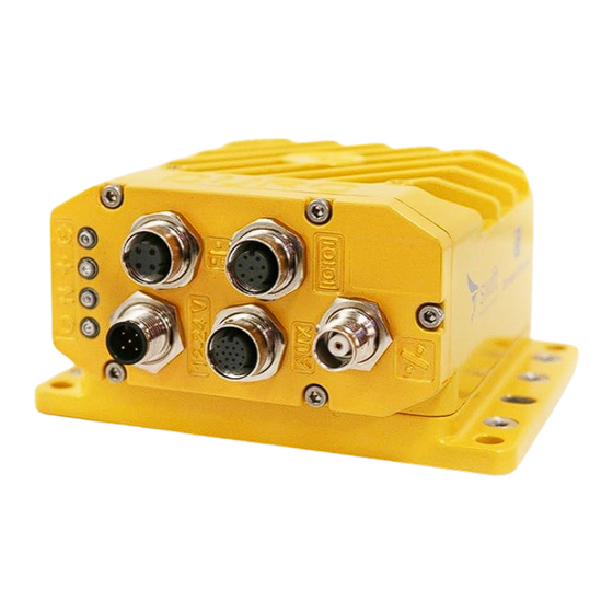
Duro Inertial is a ruggedized version of Swift Navigation's Piksi® Multi dual-frequency Real Time Kinematics (RTK) GNSS
receiver including Carnegie Robotics' SmoothPose™ sensor fusion algorithm, which combines GNSS and inertial
measurements into an unified solution. The combination of GNSS and inertial measurements allows Duro Inertial to
provide highly-accurate, continuous position solutions during brief GNSS outages and to deliver robust precision
navigation solutions in harsh GNSS environments.
Prerequisites
This document describes the installation, configuration, and operation of features specific to Duro Inertial. Users should
be familiar with the information contained in the Duro User Manual before following this guide.
Duro User Manual -
h
ttps://www.swiftnav.com/latest/duro-user-manual
www.swiftnav.com | s upport@swiftnav.com
©2018 Swift Navigation, Inc. All rights reserved | Version 1.0
Duro Inertial - User Guide
Advertisement
Table of Contents

Related Manuals for Swift Navigation Duro Inertial

Summary of Contents for Swift Navigation Duro Inertial
- Page 1 Overview Duro Inertial is a ruggedized version of Swift Navigation’s Piksi® Multi dual-frequency Real Time Kinematics (RTK) GNSS receiver including Carnegie Robotics’ SmoothPose™ sensor fusion algorithm, which combines GNSS and inertial measurements into an unified solution. The combination of GNSS and inertial measurements allows Duro Inertial to ...
-
Page 2: System Architecture
MEMS IMU in the product into one Fused RTK GNSS + INS position, velocity, and time solution. www.swiftnav.com | s upport@swiftnav.com ©2018 Swift Navigation, Inc. All rights reserved | Version 1.0 ... -
Page 3: Installation
Installation For proper Duro Inertial operation it is essential to mount both the Duro Inertial and the GNSS antenna securely and firmly to the vehicle body. During operation, the antenna and Duro Inertial must remain in the same position relative to each ... - Page 4 Ensure that the Duro Inertial enclosure is on the same rigid body as the GNSS antenna. Some suspension systems may isolate the chassis from the cab and if the antenna moves when the Duro Inertial does not it will degrade results. When ...
-
Page 5: Antenna Offset
After installing the GNSS antenna and Duro Inertial on the vehicle, the antenna offset should be measured. The antenna offset consists of X, Y, and Z components which should be measured along Duro Inertial’s X, Y, and Z axes (i.e. within the ... - Page 6 To obtain yaw, pitch, and roll angles for the orthogonal mounting, refer to Appendix B - Duro Inertial Orientations, and use the values which match your installation. One way to think of the vehicle frame orientation is the rotations required to ...
-
Page 7: Firmware Version
Firmware Settings There are a number of firmware settings which directly affect the behavior of Duro Inertial. These are detailed in the tables below. Device settings can be configured via Swift Console on the Settings tab or directly via SBP messages. ... - Page 8 Enter a ntenna_offset_x/y/z and v ehicle_frame_yaw/pitch/roll as they were measured after installation. The worksheet in Appendix C is a useful tool for determining these values. www.swiftnav.com | s upport@swiftnav.com ©2018 Swift Navigation, Inc. All rights reserved | Version 1.0 ...
- Page 9 RTK Corrections For the most precise and accurate position output, Duro Inertial should operate in RTK mode. Select and configure an RTK correction source in the same manner as a GNSS-only Duro. Refer to the Duro User Manual and support articles on the ...
-
Page 10: Operation
LED Indicators Duro Inertial uses front panel LEDs to indicate when the INS is operational and the output position is computed using both GNSS and inertial subsystem. Purple lights for the POS LED indicate that INS is in use. Refer to the LED description table ... - Page 11 The subset of Swift Binary Protocol messages directly related to Duro Inertial operation are highlighted in the tables below. When using Duro Inertial, you may need to adjust the e nabled_sbp_messages setting for the interfaces you use to communicate with the device. This setting is a comma separated list of message IDs (in decimal) that will be emitted on ...
- Page 12 A - Autonomous fix D - DGNSS or SBAS E - Dead Reckoning (Estimated) F - Float RTK R - Fixed RTK www.swiftnav.com | s upport@swiftnav.com ©2018 Swift Navigation, Inc. All rights reserved | Version 1.0 ...
-
Page 13: Known Issues
Known Issues ● Latency of Duro Inertial is dependent on the configuration of your device. Pin 17 Position Valid (PV) does not go high during Dead Reckoning ● ● NMEA will stop output after power cycle until a valid GNSS time is received ... -
Page 14: Appendix A - Identifying Duro Inertial
Duro Inertial receivers can be identified in following ways: 1. Duro Inertial has a product name and part number located on the bottom of the enclosure. 2. The “product_id” read-only setting reflects the product ID. This setting exists in the “system_info” group in the ... -
Page 15: Appendix B - Duro Inertial Orientations
Appendix B - Duro Inertial Orientations Use the pictures below to determine Duro Inertial orientation angles in your vehicle installation. Angles are in degrees. Yaw: Yaw: Yaw: Yaw: Pitch: 0 Pitch: Pitch: Pitch: Roll: Roll: Roll: Roll:... - Page 16 Pitch: 0 Pitch: Pitch: Roll: Roll: -90 Roll: Roll: Yaw: Yaw: Yaw: Yaw: Pitch: 0 Pitch: Pitch: Pitch: Roll: Roll: Roll: Roll: www.swiftnav.com | s upport@swiftnav.com ©2018 Swift Navigation, Inc. All rights reserved | Version 1.0 ...
-
Page 17: Appendix C - Duro Inertial Installation Worksheet
Appendix C - Duro Inertial Installation Worksheet Print and use this form to record Duro Inertial installation details and measurements. Antenna offset and vehicle frame rotation need to be entered to firmware settings for proper system operation. ... -
Page 18: Appendix D - Device And Vehicle Frames
For example, a rotation matrix that can be used to rotate a vector from the device frame (i.e a velocity in the Duro Inertial frame X-direction) to the Vehicle Frame, can be ... -
Page 19: Additional References
Swift Console Graphic User Interface (GUI) program providing visual representation of what's happening inside Swift Navigation’s Piksi Multi, Duro, and Duro Inertial GNSS receivers. Console displays information and allows to adjust the settings on the hardware. Available for Windows, macOS and Linux. ... - Page 20 www.swiftnav.com | s upport@swiftnav.com ©2018 Swift Navigation, Inc. All rights reserved | Version 1.0 ...
Need help?
Do you have a question about the Duro Inertial and is the answer not in the manual?
Questions and answers