Table of Contents
Advertisement
Advertisement
Table of Contents

Related Manuals for Dillon Quantrol AFG Series

Summary of Contents for Dillon Quantrol AFG Series
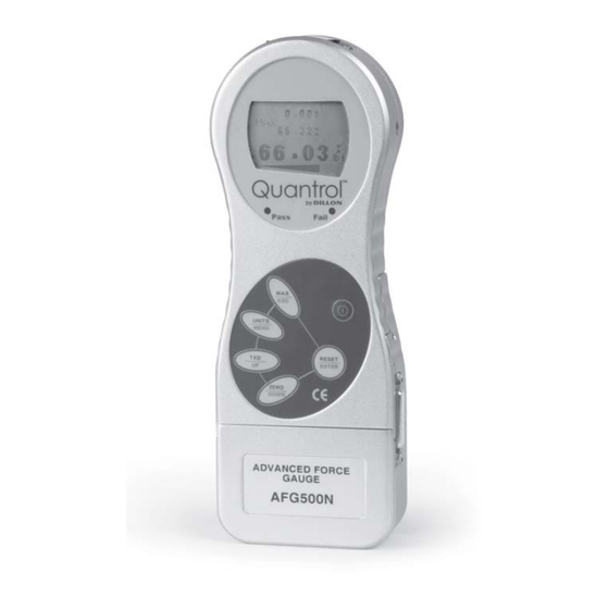
- Page 1 Advanced Force Gauge (AFG/AFTI) User’s Manual...
- Page 2 EUROPEAN COUNTRIES WARNING This is a Class A product. In a domestic environment this product may cause radio interference in which the user may be required to take adequate measures. CAUTION Risk of electrical shock. Do not remove cover. No user serviceable parts inside.
-
Page 3: Table Of Contents
Table of Contents Table of Contents ................... 3 Introduction ....................5 Before Use ....................5 Operation Overview ................5 Powering the AFG ..................5 Inserting and Charging the Batteries ............6 Using the AFG ....................6 Fitting Accessories ................. 6 Mounting to a Test Stand ................ - Page 4 Advanced Force Gauge User’s Manual...
-
Page 5: Introduction
Introduction Thank you for choosing the Quantrol Advanced Force Gauge (AFG) instrument. With correct use and regular re-calibration it will give many years of accurate and reliable service. The AFG uses the latest integrated circuit technology. It can measure tensile and compressive forces accurately, while being simple to use by the operator. -
Page 6: Inserting And Charging The Batteries
To insert the batteries, remove the battery cover on Inserting and the upper part of the rear of the gauge by undoing the Charging the 3 retaining screws. Fit the five batteries in the battery Batteries holder ensuring that you observe polarity and the batteries are placed on top of the release tag. -
Page 7: Mounting To A Test Stand
Note: When fitting a grip extension rod (5 inches long). Affix the extension rod ensure that it is screwed to the load cell probe in the hole at the bottom of the finger-tight only. gauge by tightening it gently with the fingers. Excessive torque can Your chosen grip or accessory may now be connected damage the load cell. -
Page 8: Basic Functions
* Do not overload the load sensor. This will cause irreparable damage. Forces greater than 120% of full- scale will produce an audible beep until load is released and an OL symbol will appear on the display for 30 seconds. Forces greater than 150% of full-scale will produce an All the current settings audible beep until load is released and an OL symbol... - Page 9 During the operation of the gauge it is often necessary Zeroing the Gauge to zero the display – e.g. when you wish to tare out the weight of a grip, so it does not become part of the measured reading. Press and release the ZERO key. The display will blink momentarily as the zero opera- tion is carried out.
- Page 10 Figure 3b Max Tension Figure 3c Max Compression “Normal” mode Press the MAX key again and the word MAX has now disappeared from the display. The display will now indicate forces applied in both directions as they are applied to the load sensor and maintain a live display. Press the RESET key to clear both maximum regis- ters and prepare for detecting the next maximum readings.
- Page 11 Continuous PC For sending a continuous data stream to a PC, press Communication and hold the TXD key for 2 seconds then release. TX will now appear in the display to indicate that data is Default baud rate = 9600. being sent.
-
Page 12: Optional Settings
The AFG has a display backlight that can be turned Optional Settings on at powerup. Press and hold UNITS while powering up the AFG with the key. The backlight is now Backlit Display operating. Please note that battery consumption is doubled when using the backlight. -
Page 13: Additional Force & Torque Sensors
The AFG has an interchangeable loadcell cartridge Additional Force (ALC), which allows selection of different capacity & Torque Sensors load cells to be fitted to the AFG console. Interchangeable To exchange the cartridge, power down the gauge and remove it from the test stand if it is fitted to one. Advanced Loadcell Turn the gauge face down and insert a 3mm Allen key Cartridges (ALC)’s... -
Page 14: Advanced Menu Options
‘Smart’ Sensors All Advanced Loadcell Cartridges have a 15-pin ‘Smart’ connector port on the right hand side for interface with Quantrol external ‘Smart’ force and torque sensors. This allows you to use your existing AFG console to perform additional tests without the Warning! The AFG must need for a dedicated instrument. -
Page 15: Alarm
Figure 6 Main Menu The AFG has an audible and visual alarm feature ALARM which can be set to trigger on pass, fail or sample break criteria. To set an alarm, press and hold the MENU key until page 1 of the main menu appears. The cursor arrow will point to ALARM. - Page 16 ALARM sub-menu 3 The display shows AUDIBLE, LED and BOTH with the arrow cursor indicating which feature is selected. This menu selects how the PASS/FAIL status of a value will be indicated. AUDIBLE Only the audible alarm will be activated when the value is a PASS/FAIL The green and red LED’s will indicate the PASS /FAIL status.
- Page 17 Figure 8 Alarm symbol ALARM on break This feature is only activated when the % DROP feature is used in conjunction with the ALARM function. The AFG looks for a percentage (of full- scale) drop from peak load value, set in the % DROP menu.
- Page 18 Example 1 Settings: - - BOTH LED and audio alarms are active - Alarm triggers on OUT BAND - Alarm is set to FAIL - % DROP is 10% of fullscale (e.g. AFG 100N must register drop of 10N) Main display is set to 1st peak tension screen Example 2...
- Page 19 Example 3 Settings: - - BOTH LED and audio alarms are active - Alarm triggers on OUT BAND - Alarm is set to FAIL - % DROP is 10% of full-scale (e.g. AFG 100N must register drop of 10N) Main display is set to 1st peak tension screen Example 4...
-
Page 20: Plc (Programmable Limit Controller)
Example 5 Settings: - - BOTH LED and audio alarms are active - Alarm triggers on OUT BAND - Alarm is set to FAIL - % DROP is 10% of fullscale (e.g. AFG 100N must register drop of 10N) Main display is set to 1st peak tension screen The AFG has a load output signal which may be used... -
Page 21: Stand
PLC sub-menu 2 The display will show SET and a default load limit at which the output signal will trigger the relay. To set the required load limit use UP and DOWN keys to adjust the value and ENTER to confirm the selec- tion. - Page 22 REVERSE Select UP or DOWN to tell the gauge which direction sub-menu 1 the stand will begin to move before the load-limit is reached. REVERSE BREAK - Sets the gauge to reverse at sample break. sub-menu 2 Press ENTER to select. Break sub-menu 1 SET % of load cell capacity to indicate the value by which the load must fall to determine a break.
-
Page 23: Freeze
This feature is used to ‘freeze’ the main-display when FREEZE an external signal is received. The AFG can be configured to freeze when going either low 1-0 (LO) or high 0-1 (HI). This is particularly useful for applica- Key: tions where a significant event occurs which must be 1 = 5.0 V 0 = 0.0 V captured (e.g. - Page 24 Figure 11 1st Peak Tension and Compression % DROP sub-menu 1 The display will show % DROP OFF and SET. Press ENTER to change % DROP OFF to % DROP ON. Press DOWN to move the arrow cursor to SET % and press ENTER.
-
Page 25: Average/Time
Average/Time This function allows the average load reading to be displayed. The average starts being calculated when the threshold (% of full-scale) is reached and stops being calculated when the load falls back below this threshold. To set AVERAGE over TIME, press and hold the MENU key until page 1 of the main-menu appears. -
Page 26: Rate
RATE This function selects the display throughput rate, i.e. the amount of averaging performed by the internal electronics before the load reading is displayed. There are three levels HI, MED and LO. Display updates quickly with little data averaging (2000 Hz) Gauge default. -
Page 27: Footswitch 2
To assign the function of a key to FOOTSWITCH 2 FOOTSWITCH 2 use UP and DOWN to move the arrow key to FOOTSWITCH 2. Using UP and DOWN select the relevant key (MAX, UNITS, TXD, ZERO or RESET) and press the ENTER key. Press ESC to return to page 2 of the main-menu. -
Page 28: Information
The transmission (or Baud) rate can now be set. Port sub-menu 2 Use the UP or DOWN key to position the arrow cursor at the relevant speed (2400, 9600, 57600 or 115200). Press ENTER to select. You will now return to page 2 of the main menu. To set STORE MEM press ENTER from Comms sub- menu 1. -
Page 29: X/Constant
If the current % offset is as shown below, follow the appropriate action. Lower Value Action -4.9% to 4.9% Normal offset provided upper and lower values are within 5% of each other -5.0% to -9.9% Contact Quantrol distributor 5% to 9.97% for recalibration -10% and greater Contact Quantrol distributor... -
Page 30: Afg Specifications
AFG Specifications Range & Resolution Model no: mN AFG2.5 2,500 x 0.5 2.5 x 0.0005 - 250 x 0.05 9 x 0.002 0.55 x 0.0001 AFG 5 5,000 x 1 5 x 0.001 500 x 0.1 0.5 x 0.0001 18 x 0.005 1.1 x 0.0002 AFG 10 10,000 x 2 10 x 0.002... - Page 31 PLC Cable Supply voltage: The relay is powered from a 5 volt regulator inside the AFG Input control: The relay state is controlled via a TTL signal from the AFG and is in a “closed position” when a logic ‘1’ input is applied. Output characteristics Peak relay ac voltage: 350 volts...
- Page 32 * Shown with AFG Mk 3 D Connector Pin Out: dovetail mounting bracket (supplied Analog Output with Dillon Test RS232 Transmit Stand) RS232 Receive Mitutoyo Clock Output Mitutoyo Ready Output + 5 Volts FREEZE Reading Input Stand Reverse UP Footswitch 2 Input/SMART -ve out...
-
Page 33: Appendix: Menu Flowcharts
Appendix: Menu Flowcharts On the following pages are flowcharts to help you navigate the menus found in the AFG. They appear in the order they appear on the two pages of the main menu. Alarm Advanced Force Gauge User’s Manual... - Page 34 Advanced Force Gauge User’s Manual...
- Page 35 Freeze % Drop Average/Time Rate Advanced Force Gauge User’s Manual...
- Page 36 Footswitch1 Footswitch2 Comms Constant Advanced Force Gauge User’s Manual...
- Page 37 Information Calibration Contrast Advanced Force Gauge User’s Manual...
- Page 38 Advanced Force Gauge User’s Manual...
- Page 39 Advanced Force Gauge User’s Manual...
- Page 40 Dillon A division of Weigh-Tronix Inc. 1000 Armstrong Dr. Fairmont, MN 56031 USA Telephone: 507-238-4461 Facsimile: 507-238-8258 e-mail: dillon@weigh-tronix.com www.quantrol.com Precision Force Measurement Testing Systems...
Need help?
Do you have a question about the Quantrol AFG Series and is the answer not in the manual?
Questions and answers